1
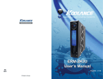
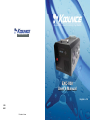
®
Superior Liquid Cooling Systems
www.koolance.com
EXC-800
User’s Manual
English v1.0
ISO
9001
Printed in Korea
This User Manual is updated regularly. Please be sure to check our support page for a newer
version of this guide: www.koolance.com
GENERAL PRECAUTION
Please read this manual carefully before beginning the installation of your Koolance system.
This manual assumes the user has basic experience in building and configuring computer
systems. Information referring to traditional hardware assembly is intentionally brief.
ABOUT SIGNS
Throughout this document, critical information is highlighted in gray-colored boxes. The
following symbols are intended to help prevent any situation which may cause personal
injury and/or damage to equipment:
!
!
WARNING: Indicates a potentially hazardous situation which, if not avoided,
could result in personal injury or be life-threatening.
CAUTION: Indicates a potentially hazardous situation which, if not avoided,
may result in damage to equipment or property.
PROHIBITED: Indicates a prohibited action.
PROHIBITED USE
This product is designed, developed and manufactured as contemplated for general use,
including without limitation: general office use, personal use and household use, but is not
designed, developed and manufactured as contemplated for use accompanying fatal risks or
dangers that, unless extremely high safety is secured, could lead directly to death, personal
injury, severe physical damage or other loss, including without limitation: nuclear power core
control, airplane control, air traffic control, mass transport operation control, life support,
or weapon launching control. If these products are used in such hazardous environments,
Koolance Incorporated does not warrant them.
TRADEMARKS
The Koolance name and logo are trademarks or registered trademarks of Koolance, Inc.
Other company and product names used in this publication are for identification purposes
only and may be trademarks or registered trademarks of their respective companies.
COPYRIGHT
All rights reserved. Copyright (C) Koolance Incorporated.
User Manual
1
!
WARNING: The Koolance liquid coolant contains chemicals which may
be harmful or fatal if swallowed. KEEP THIS AND ALL DANGEROUS
CHEMICALS OUT OF THE REACH OF CHILDREN. Please refer to
the coolant MSDS available on our website: www.koolance.com
Table of Contents
System Diagram ............................................................................................. 4
Positioning the System ................................................................................... 5
External Fittings .............................................................................................. 5
!
CAUTION: Always keep the EXC-800 chiller upright during operation.
Additionally, THE UNIT MUST BE KEPT UPRIGHT FOR AT LEAST
24 HOURS BEFORE POWERING ON. This is to allow enough oil to
reach the compressor. Powering-on the unit too early can permanently
damage the compressor and is not covered by the product warranty.
Coolant Filling and Powering-On .................................................................... 7
Display Panel .................................................................................................. 8
Temp Set ......................................................................................................... 9
Alarm Set ...................................................................................................... 10
Relay Set ...................................................................................................... 10
!
CAUTION: The EXC-800 chiller is specific to one input voltage (either
110VAC or 220VAC) and will not auto-switch between these voltages.
Supply only the proper input voltage, as labeled above the AC plug on
the rear of the unit. Supplying the improper voltage can damage the
unit and is not covered by the product warranty.
Pump Set ...................................................................................................... 11
Display Set .................................................................................................... 11
Troubleshooting ............................................................................................ 13
Limited Warranty ........................................................................................... 14
!
!
CAUTION: This cooling system can chill liquid below the ambient air
temperature, which may cause condensation to form on tubing and cold
plates. It is highly recommended to keep the temperature at or above
the ambient temperature. (See “TEMP SET” for details.)
CAUTION: Do not use a temperature set-point that is below the
coolant’s freezing point. This may damage the cooling unit and is not
covered by the product warranty. It is recommended to always keep
the temperature set-point at or above ambient temperature.
KOOLANCE CONTACT INFORMATION
Koolance Incorporated (USA)
Address:
Telephone:
Fax:
Sales Email:
Tech Email:
Web:
2
Product Specifications
- Weight: 26kg (approx.)
- Dimensions: 270 x 360 x 245mm (approx.)
- Operating Temperature Range: Ambient 0-40°C, Water 0-40°C
- Cooling Capacity: 800W (2730 BTU/hr) @ 25°C liquid/ambient
- Refrigerant: R-134a
- Pump: Koolance P/N PMP-500
- Power Input: (Depends on model), either 110VAC or 220VAC
- Power Consumption: 450W @ 25°C, 650W @ 35°C (approx.)
2840 W. Valley Hwy. N., Auburn, WA, USA 98001
+01-253-249-7669
+01-253-249-7453
[email protected]
[email protected]
www.koolance.com
User Manual
3
System Diagram
Positioning the System
Fill Port
!
Carrying Handles
LED Display Panel
CAUTION: Always keep the EXC-800 chiller upright during operation.
Additionally, THE UNIT MUST BE KEPT UPRIGHT FOR AT LEAST
24 HOURS BEFORE POWERING ON. This is to allow enough oil to
reach the compressor. Powering-on the unit too early can permanently
damage the compressor and is not covered by the product warranty.
The chiller must be run upright at all times. Upon arrival of this product via
transport or courier shipping, it must be kept upright FOR AT LEAST 24
HOURS BEFORE BEING POWERED ON to allow enough oil to reach the
compressor.
Control Panel
Power Switch
Condenser Fans
Relay & Thermocouple
Terminals (Optional)
OK!
Power Connection
Coolant Inlet
& Outlet
Reservoir Level
Drain Plug
4
NO!
NO!
External Fittings
Install the G 1/4 BSPP threaded fittings
you purchased for your cooling system. It’s
recommended to hand-tighten all fittings to
avoid damaging the cooling unit.
Parallel threads seal at the included o-ring.
Do not use any plumber’s tape or putty on
the threads, which can interfere with the
o-ring seal.
User Manual
5
Cut tubing into two segments. You
will need to connect each to the rear
nozzles.
Each hose connection will use a threaded compression
ring or hose clamp to keep it secure. Be sure to thread
the compression ring or hose clamp onto the hose
before attaching it.
Slowly fill the system with coolant. To maintain
the product warranty, use only Koolance
approved coolant. Many alternative liquids
and additives can cause permanent damage
to the cooling unit (through chemical reaction,
corrosion, biological growth, thermal expansion, viscosity, etc.).
Replace the fill port on the reservoir. Do not overtighten the fill
port.
Squeeze the tube while pushing it firmly over
the fitting. Tubing should completely cover the
fitting or barb.
Tighten the connection by sliding the
compression nut down over the fitting and
screwing securely. For hose barbs, use pliers
to move it into the proper position before
releasing.
Coolant Filling and Powering-On
!
WARNING: Most coolants are electrically conductive. Use caution
when filling the system, and keep all liquids away from electronics and
power cables. Keep the primary AC power cable unplugged whenever
filling or draining coolant.
Once all devices (cold plates, fittings,
etc.) have been connected with tubing, the system can be filled with coolant.
The fill port is located on top of the system over the
reservoir. Remove the large slot-headed screw with
a screwdriver or large coin.
6
Power on the cooling unit. Set the pump to the highest speed setting until
most of the air in the cooling loop has been pushed into the reservoir. Once
this occurs, the liquid noise will drop. This process can take several minutes,
depending on the filling technique and what’s connected to the system.
During this process, components may need to be tilted gently
to assist with air evacuation. The reservoir level will decrease
during this procedure. Remove the fill port cap and add more
liquid as needed.
Maximum and minimum fill markings are provided on the back
side of the unit to help maintain the coolant level.
!
CAUTION: The EXC-800 chiller is specific to one input voltage (either
110VAC or 220VAC) and will not auto-switch between these voltages.
Supply only the proper input voltage, as labeled above the AC plug on
the rear of the unit. Supplying the improper voltage can damage the
unit and is not covered by the product warranty.
Insert the main power cable
into the cooling unit and
connect the other end to an
appropriate AC wall outlet.
Be sure the supply voltage
matches what’s labeled on
the unit. The product will
not accept both 110VAC and
220VAC
User Manual
7
TEMP SET
Display Panel
The Koolance display panel allows control and monitoring of various aspects of
the cooling unit. 4 buttons are used, with directional arrows to navigate or change
settings, and a center button to select/exit.
!
CAUTION: This cooling system can chill liquid below the ambient air
temperature, which may cause condensation to form on tubing and
cold plates. It is highly recommended to keep the temperature at or
above the ambient temperature. (See below for details.)
!
CAUTION: Do not use a temperature set-point that is below the
coolant’s freezing point. This may damage the cooling unit and is not
covered by the product warranty. It is recommended to always keep
the temperature set-point at or above ambient temperature.
Navigate Up,
Increase Setting
Navigate
Left
◙
Navigate
Right
Enter/Exit
Navigate Down,
Decrease Setting
Under “TEMP SET”, you can select the active temperature sensor and set-point
the chiller will try to follow. There are four temperature options to select from. Press
▼ and ▲ to scroll among these options:
◙
for 3 seconds to change display units between
• On the main screen, hold
°C/°F and LPM/GPM.
• You can exit any menu and return to the main screen by holding
for 2
seconds.
• To reset ALL settings to default, hold ▼ + ▲ for 3 seconds.
▲ LIQ TEMP: Liquid temperature (Range: 1 to 50°C)
EXT TEMP: Rear sensor, if attached (Range: 1 to 149°C)
LIQ-AMB: Delta-T between liquid & ambient (Range: -50 to 50°C)
▼ EXT-AMB: Delta-T between rear sensor & ambient (Range: -50 to 50°C)
◙
Main Menu
To enter the main menu, briefly press
Use ▼ and ▲ to navigate this menu.
◙. The selected option will begin flashing.
▲ TEMP SET: Temperature set-point adjustment
ALARM SET: Alarm settings
RELAY SET: Relay Trigger settings
PUMP SET: Pump speed settings
▼ DISPLAY SET: LCD display settings
When in the top menu, press
here, press ◄.
◙ to enter one of the above categories. To exit from
This unit provides a terminal on the rear for
connecting a K-type thermocouple (not included)
for external monitoring and temperature
configuration.
User Manual
◙
LIQ TEMP= 28C
Maintain coolant coming from the chiller at 28°C
EXT TEMP= 50C
Maintain the external sensor at 50°C (if attached)
LIQ-AMB=
-5C
Maintain a difference between the liquid and ambient
air of -5°C (keep liquid 5°C below ambient)
EXT-AMB=
5C
Press
menu.
External Sensor
8
The sensor currently displayed in this menu is what the chiller will follow.
Only one can be active. Press
to adjust the target temperature value using ▼
and ▲. Below are some examples:
Maintain a difference between the external sensor and
ambient air of +5°C (keep sensor 5ºC above ambient)
◙ again to exit configuration of the sensor. Press ◄ to return to the previous
With these settings, it’s possible to set the liquid temperature below the environmental
air temperature. If liquid temperatures reach the ambient dew point, condensation
(water droplets) can form on tubing and cold plates connected to the chiller. Unless
condensation is prepared for, it is recommended to keep the chiller on “LIQAMB” with a minimum value of 0°C (which keeps liquid at ambient).
8
User Manual
9
ALARM SET
This menu affects when the built-in audio alarm will sound. Upon entering the
alarm menu, the temperature delta-t value will flash. Press ▼ or ▲ to adjust this
value. Press
to accept and return to the previous menu.
◙
PUMP SET
WARNING: The cooling system’s pump can not be run dry for any
period of time. Never power-on the chiller without sufficient liquid in
the reservoir. Dry-running (and thereby damaging the pump) is not
covered under the Koolance product warranty.
!
ALARM SET
(TEMP SET) ± 5C
In the above example, the alarm will sound if the temperature exceeds a 5°C
difference (+ or -) from the chiller’s currently active temperature sensor (see “TEMP
SET”). The maximum delta-T setting range for the alarm is 49°C.
The pump speed can be manually set from 1 (lowest) to 10 (highest):
The regular audio alarm is a repeating beep. If a steady alarm tone is heard, this
indicates the relay has also been triggered (see “RELAY SET”).
The pump speed level will flash. Press ▼ or ▲ to adjust. Press
previous menu.
NOTE: The alarm temperature must be at least 1°C (1-2°F) lower than the relay
temperature. If an alarm temperature can not be increased, first increase the relay
temperature. Likewise, if a relay temperature can not be decreased, first decrease
the alarm temperature.
RELAY SET
Rear terminals are provided for a temperatureconfigurable relay. Wires can be connected as
normally-open (NO), or normally-closed (NC),
labeled below the terminals.
To adjust the relay trigger point, enter the “RELAY
SET” menu. Press ▼ or ▲ to adjust this value.
Press
to accept and return to the previous
menu.
◙
RELAY SET
(TEMP SET) ± 40C
In the above example, the relay will trigger if the temperature exceeds a 40°C
difference (+ or -) from the chiller’s currently active temperature sensor (see “TEMP
SET”). The maximum delta-T setting range for the relay is 50°C.
NOTE: The relay temperature must be at least 1°C (1-2°F) higher than the alarm
temperature. If an alarm temperature can not be increased, first increase the relay
temperature. Likewise, if a relay temperature can not be decreased, first decrease
the alarm temperature.
10
7LV : Pump Speed Level
PUMP(1-10)
◙ to return to the
DISPLAY SET
The display settings configure which values you wish to appear on the front display
and how they are shown:
DISPLAY
FIXED
CYCLIC : Show 2 fixed values or cycle multiple values
The first option, “FIXED”, will flash. Press ◄ or ► to change between these
options. Press
to configure one of the selections, or press ▲ to exit. If “FIXED”
is selected, two lines will be shown:
◙
LIQ SET
EXT TEMP
20C : First line display option
21.4C : Second line display option
The first line will flash. Press ▼ or ▲ to change what this line will display:
▲ LIQ SET : (Field varies) Shows current active sensor and user set-point
AMB TEMP : Shows ambient air temperature
LIQ TEMP : Shows reservoir liquid temperature
EXT TEMP : Shows external sensor temperature (if connected)
FAN : Shows condenser fan RPM
PUMP : Shows pump impeller RPM
▼ FLOW : Shows liquid flow rate through the unit
◙
Press
to move to line 2, and similarly use ▼ or ▲ to choose what will be
displayed on the second line. Press
again to exit.
◙
User Manual
11
If “CYCLIC” is chosen from the DISPLAY SET menu, multiple values can be rotated
through the front display.
◙
The first line will flash. Use ▼ and ▲ to navigate to other lines. Press
to enable
or disable each value. This will remove the asterisk, thereby hiding that line from
being shown on the main screen:
▲ *LIQ SET : (Field varies) Show current active sensor and user set-point
*AMB TEMP : Show ambient air temperature
LIQ TEMP : Hide liquid temperature
*EXT TEMP : Show external sensor temperature (if connected)
FAN : Hide condenser fan RPM
PUMP : Hide pump impeller RPM
*FLOW
: Show liquid flow rate through the unit
▼
Press ◄ to return to the previous menu, or press ► to exit DISPLAY SET.
Troubleshooting
We hope your Koolance system will provide you with years of reliable cooling
performance. To help avoid unnecessary RMA issues, we have prepared this list
of possible operational problems, and their most common solutions.
1. After filling the reservoir with coolant and turning on the system, there are no
visible signs of liquid movement...
Check the flow meter value (see “DISPLAY SET”). If there is no detected flow
immediately after filling the reservoir, or the flow rate is very low or periodic,
this usually indicates the pump has not finished priming. Open the fill port on
top of the chiller and temporarily set the pump speed to 10 (see “PUMP SET”)
to help push out the air.
If possible while the pump is running, gently tilt your cold plates or other
components connected to the chiller in various directions to assist with
bleeding air from the cooling loop. If it becomes necessary to tilt the chiller to
assist with priming, close the fill port and power-off the unit before doing so.
3. The temperature alarm sounds and I’m not sure why...
The active temperature sensor and value will flash in the front display whenever
an alarm sounds. Check that your currently selected temperature sensor and
alarm are configured as desired (see “TEMP SET” and “ALARM SET”). If you
are certain the cooling system is working properly otherwise, try resetting all
system settings by holding ▼ + ▲ for 3 seconds.
4. My system appears to be leaking fluid or water...
Check that the fittings on the rear inlet/outlet and drain plug are securely tightened (by hand, not with tools). They are parallel type threads, so no plumber’s
tape or putty should be used or this can interfere with proper sealing.
If during operation the outsides of your tubing or cold plates is wet, this can
indicate condensation. The chiller temperature setting should not be lower than
the ambient room air temperature. (See “TEMP SET” for recommendations.)
5. The front display is locked up or not responding.
Reset all system settings by holding ▼ + ▲ for 3 seconds. After a reset, all configuration settings (temperature, alarm, fans, etc.) must be updated again.
12
User Manual
13
Limited Warranty
Koolance Incorporated (“Koolance”) warrants each new Koolance liquid-cooled
system (“the system”), against defects in materials or workmanship for a period of
one year from the date of purchase, and agrees to repair or replace any defective
Koolance system without charge. Shipping costs are non-refundable.
This warranty is non-transferable. All warranty claims must be accompanied by the original
proof of purchase.
THIS WARRANTY DOES NOT COVER DAMAGE RESULTING FROM ACCIDENT,
MISUSE OR ABUSE, LACK OF REASONABLE CARE, SHIPPING DAMAGE,
MODIFICATIONS, THE AFFIXING OF ANY ATTACHMENT NOT PROVIDED WITH
THE PRODUCT, LOSS OF PARTS, OR OPERATING COMPONENTS AT SPEEDS OR
FUNCTIONS OTHER THAN THOSE SPECIFIED BY THEIR MANUFACTURERS.
Use of unauthorized replacement parts or liquids will void this warranty. Koolance
Incorporated will not pay for warranty service performed by a non-authorized repair
or diagnostic service and will not reimburse the consumer for damage resulting from
warranty service performed by a non-authorized repair service. No responsibility is
assumed for any special incidental or consequential damages due to a defective Koolance
product.
In order to obtain warranty service, contact our RMA department for information. The
product must be shipped postage prepaid to an authorized Koolance service location. It
is suggested that, for your protection, you return shipments of product by insured mail,
insurance prepaid. Damage occurring during shipment is not covered by this warranty.
Shipping costs are non-refundable. No other warranty, written or oral, is authorized by
Koolance Incorporated.
Disclaimer
IN NO EVENT SHALL KOOLANCE INCORPORATED OR ITS EMPLOYEES, AGENTS,
SUPPLIERS, MANUFACTURERS, OR CONTRACTORS BE LIABLE FOR ANY
DAMAGES OF ANY KIND OR CHARACTER, INCLUDING WITHOUT LIMITATION
ANY COMPENSATORY, INCIDENTAL, DIRECT, INDIRECT, SPECIAL, PUNITIVE, OR
CONSEQUENTIAL DAMAGES, LOSS OF USE, LOSS OF DATA, LOSS OF INCOME OR
PROFIT, LOSS OF OR DAMAGE TO PERSONS OR PROPERTY, CLAIMS OF THIRD
PARTIES, OR OTHER LOSSES OF ANY KIND OR CHARACTER, AND WHETHER
OR NOT THE POSSIBILITY OF SUCH LOSS OR DAMAGE HAS BEEN NOTIFIED TO
KOOLANCE INCORPORATED.
14