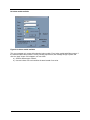
1
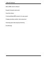
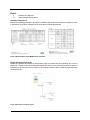
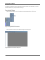
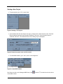
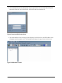
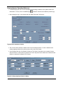
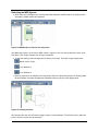
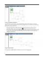
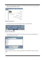
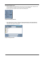
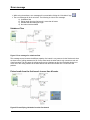
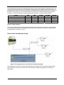
User Manual
UM-07-M03-MSS
MDS Selection Software
Engineered for flexibility and performance.TM
1
Table of Contents
What is MDS selection software?
Required information and results
Using this software
Creating additional MDS system for the same project
Changing operating condition / basic parameters
Generating report and piping layout drawing
Error Message
User Manual UM-07-M03-MSS
The data and suggestions in this document are believed current and accurate at the time
of publication, but they are not a substitute for trained, experienced and professional service.
Individual applications and site variations can significantly affect the results and
effectiveness of any information, the reader must satisfy him/herself regarding the
applicability of any article and seek professional evaluation of all materials. McQuay
disclaims any responsibility for actions based on this document.
User Manual UM-07-M03-MSS
What is MDS Selection Software?
The MDS selection software is a convenient tool to guide user to make the appropriate selection for
MDS application. Unlike any conventional system, which consist only a pair of refrigerant piping
connecting one indoor with one outdoor, the MDS system offers more with branches and joints
connecting multiple indoors to only one outdoors. Besides that, it has the ability to calculate and select
the suitable indoors unit base on the cooling / heating requirement. Once user is satisfied with the
selection, the software is able to generate a report, consisting on the selected units; type of joints
required as well as the length of different pipe diameter used in the system and other information.
User Manual UM-06-M01-MSS
3
Required Information & result
Like any other selection software, a list of information is required before we can start designing the
system. Once selection is completed, the software will be able to generate a report of units and
accessories requirement.
Required Information
i)
ii)
iii)
iv)
Air-conditioned area
Type of Indoors models
Air-conditioned size and operating condition
Proposed piping layout
Air-Conditioned Area
Before doing any selection, it would be recommended to obtain the architectural drawing from the
client. Go through the drawing and identify
a) Area to condition
b) Suitable location of outdoors and indoors
Figure 1 Plan View
Type of Indoor Models
Base on the functions of the air-conditioned area, select the suitable model. MDS system can couple
with various indoors model.
Model
Ceiling Concealed Type
Ceiling Cassette Type
Ceiling Convertible Type
Wall Mounted type
User Manual UM-06-M01-MSS
Name
MCCD-C
MCKD-A/C
MCMD-C/D/E
MWMD-G
Capacity (Btu/h / kW)
9600 ~ 56000 / 2.8 ~ 16.4
9600 ~ 47800 / 2.8 ~ 14.0
12300 ~ 56000 / 3.6 ~ 16.4
8500 ~ 22200 / 2.5 ~ 6.5
4
Air-conditioned size and operating condition
From the drawing, determine the area (m2) that each indoor is required to air-condition. Besides that,
user is also required to determine the cooling/heating capacity reference for each function of the airconditioned area / room type. The operating condition is also necessary for the software to simulate
the possible capacity change of the system. Some of the parameter for the operating conditions is
such as
a) outdoor and indoor ambient temperature
b) location of outdoor versus indoors
c) maximum piping length
d) indoor capacity to outdoor capacity ratio
Proposed piping layout
Using the software, draw the piping layout and indoors unit. The software will selects the unit base on
the cooling/heating capacity reference set and indoor, outdoor operating temperature.
Figure 2 MDS Piping Layout
User Manual UM-06-M01-MSS
5
Result
i)
ii)
Schedule of equipment
Output designed piping layout
Schedule of Equipment
Base on the drawing generated in the selection software and the selected models, this software is able
to generate a report which consisting of the units and all required accessories.
Figure 3 Standard Report from MDS Selection Software
Output designed piping layout
Besides the schedule of equipment, this software is able to generate the piping drawing into a form of
bitmap file. This picture file can be attached together with the previous report as the selection report for
submission or as a record for future reference. Constructors will then able to install the equipment base
on this picture file.
Figure 4 Picture file of Piping Layout
User Manual UM-06-M01-MSS
6
Using this software
Visit McQuay e-Distributors website to download this selection software. Once download, user need to
install this software to any computer before start using it.
Executing the Software
¾ After successful installation, user will be able to access the program from the “Start” menu.
Figure 1 Starting MDS Selection Software
¾ Once the software is executed, the software will appear as a new window.
Figure 2 MDS Selection Software Workplace
User Manual UM-06-M01-MSS
7
Starting a New Project
¾ To start a project, go to “File”, select “New”
Figure 3 Starting a new project
¾ A new window with title “New Project” will pop up. Determine the folder location at the “File Path”.
Enter the project name at the box beside the wording “File name”. Once the project name is
confirmed, click “OK”. The window will then close, leaving only the workplace.
Figure 4 Determine project name and file location
¾ To create MDS outdoor, go to “Unit”, select “unit management”
Figure 5 Create MDS Outdoor
Hint! User can click on the “Manager MDS Group” logo
create MDS outdoor.
User Manual UM-06-M01-MSS
, located 3rd from the left at the icon bar to
8
¾ A new window with title “Unit Management” will pop up. Give the new unit a name by entering the
name at the “New Unit” box. Once confirm, click on the “New” to create the unit.
Figure 6 Determine MDS Outdoor Name
¾ The window will then close, leaving only the workplace. At the left column, the MDS outdoor name
will appear under the project name. The workplace will change from grey colour to white colour.
Figure 7 MDS outdoor created
User Manual UM-06-M01-MSS
9
Entering System Operating Reference
¾ To start inserting the units on to the workplace, the operating conditions of the system need to be
determined. To do so, click on the MDS logo
(located 5th from the left, beside the pointer logo)
¾ After clicking the logo, a new window with title “Basic Parameter” will pop up.
Figure 8 Basic parameter window
¾ The current window shows the default value for the new MDS outdoor. In order to determine the
cooling capacity reference for various rooms, click on the “Edit” button.
¾ A new window with title “Cool Setting” will pop up. The “Name” drop down menu consists of some
reference base on various cities or projects. The “Unit” drop down menu allows user to determine the
whether to operate the software in SI or metric.
Figure 9 Cooling capacity reference setting
User Manual UM-06-M01-MSS
10
¾ If there is a requirement for new type of rooms, user is allowed to enter them. Click on ”SetOther”, a
new window will pop up. Type in the rooms name and the cooling capacity reference. Once the data
is confirmed, click “OK”
Figure 10 Additional room type
¾ After all changes of the cooling capacity references are confirmed, type in the name of this project at
the column “New Name”, then click “Add”. After that, the project name will appeared at the “Name”
drop down menu. Once confirm, click on “OK” to return back to the basic parameter setting window.
Figure 11 Confirm New Cooling Capacity Reference
Caution! After any changes made on cooling capacity reference, please click on the “Update” button. This
will save the data on to particular cities or projects.
¾ The roof factor only is applicable when the unit is installed under the roof. The cooling capacity
reference will multiple the “roof factor” when the unit is selected under top layer. For more
information, please refer to Figure 17 in the same chapter for more information.
User Manual UM-06-M01-MSS
11
¾ At the “Basic Parameters” window, the cooling capacity reference will shows the data previous
selected. Base on the project criteria, enter the remaining data. Once all data is confirmed, click “OK”
o Height Diff. (m)
This determines the level of the outdoor unit versus the indoor unit. If the outdoor is
located above all indoors unit, click on “Positive Height Diff”. The maximum value is 50m.
If the outdoor is located below above all indoors unit, click on “Negative Height Diff”. The
maximum value is 40m.
o
Cooling Condition
Cooling cycle condition for indoors and outdoor.
o
Heating Condition
Heating cycle condition for indoors and outdoor.
o
Occupied coefficient
Value range from 50% to 120%.
50% - The total indoors capacity is 50% or more less than the outdoor capacity.
Example:
Total Indoors Capacity = 120,000 Btu/h
MDS Outdoor Capacity = 240,000 Btu/h
120% - The total indoors capacity is 120% or less than the outdoor capacity.
Example:
Total Indoors Capacity = 120,000 Btu/h
MDS Outdoor Capacity = 100,000 Btu/h
o
Type of Refrigerant
This determines the type of refrigerant that is required for the selection. Click on the drop
down menu, it will show 2 types of refrigerant available, R22 and R410A.
Figure 12 Confirm all data in the Basic Parameter
User Manual UM-06-M01-MSS
12
Sketching the MDS System
¾ Once return to the workplace, the mouse pointer had changed to a MDS outdoor. By clicking on the
work place, a MDS outdoor will appeared.
Figure 13 MDS Outdoor created on the work place
Hint! When the pointer is in the form of MDS outdoor, suggest to click it on the top left hand corner of the
work place. This will give a better view during unit selection.
¾ To start the drawing, select the pipe joint by clicking on the logo. There are 3 types of pipe joints.
Refnet Joint or Y-joint.
1 to 3 distributors
1 to 4 distributors
¾ Once the type of joint is selected, the mouse pointer will turn to that particular joint. By clicking inside
the small square, branches will appeared. Repeat this step to get your desire piping layout.
Figure 14 Creating branches
Hint! Increase the view size will result in bigger “square” in the workplace. This will allow user to place the
joints or indoors unit into the square easier.
User Manual UM-06-M01-MSS
13
Figure 15 Complete piping layouts
Hint! Remember to save the project. This is a suitable time for user to save the project. To save the
project, go to the “File” drop down menu and select save. Besides that, user can click on the “Save” logo,
which is the first logo at the tool bar.
¾ After all the branches are created, users can move them to have around. In order to move or
rearrange the branch, click on the “pointer” logo
. After that, click on the respective joint.
¾ The joint and the items after it will be highlighted in red colour. Left click on the joint, hold it and move
the joint to the required location. Once the location is confirmed, release it. The move object will
remain at the new location.
Figure 16 Moving object
Hint! Clicking on the MDS outdoor will enable user to move the whole piping layout.
User Manual UM-06-M01-MSS
14
Selecting Indoors and determine indoors reference
¾ To insert the indoors, select the required indoors model and place it inside the square.
Figure 17 Insert Indoors
¾ Once all indoors are placed accordingly, user is required to determine the indoor model. To do so,
click on the “pointer” logo. Double click at the respective indoor model.
¾ A new window with title “Indoor Unit Cooling Capacity” will pop up.
Figure 18 Indoor unit cooling capacity
User Manual UM-06-M01-MSS
15
o
o
o
o
o
o
Room Name:
This allow user to determine the name of the room
Area
The software will calculate the suitable model base on the area of the room. User is
required to provide the area of the room.
Facing Direction
User will need to determine the direction of the external wall for the room.
Floor Number
User is allowed to determine the room location
Standard Layer
The room is the middle floor location. Unit is not installed under the roof.
Top Layer
The room is at the top floor. Unit is installed under the roof.
Function
User is required to determine which cooling capacity reference to use. The cooling
capacity reference is set previously. Refer to Figure 8 (same chapter) for more
information.
Model
Once user clicks on the “Apply”, this software will select the appropriate model. However,
if user wishes to change the model, he or she can select it by click on the drop down
menu button.
¾ Once user is satisfied with the selection, click on box beside the “Appoint Indoor”. By doing soon,
user had “locked” the information. All information of the particular indoor cannot be change. This is to
avoid user accidentally change the information. If user wishes to change the information, just un-tick
the box.
Figure 19 Secured the indoor information
User Manual UM-06-M01-MSS
16
¾ After all indoors information is completed, user is required to provide the estimated piping length of
each branches. Initially, all piping length is shown as 0m. To enter the piping length, firstly, ensure
that the “pointer” logo is still active. Secondly, move the pointer to the respective piping length. The
piping length will change to a box, allowing user to enter the desire length.
Figure 20 Entering desire piping length
Figure 21 Complete piping lengths
User Manual UM-06-M01-MSS
17
Selecting Outdoor
¾ Once all piping length is completed, user is now able to size the outdoor unit. Go to the “Unit” drop
down menu, select “Current Unit”, select “Calculate”.
Figure 22 Sizing outdoor unit
¾ A new window with title “Please select outdoor unit-R22” will pop up. The suitable outdoor model will
be highlighted in bold.
¾ The cooling capacity, heating capacity and maximum indoor unit will be listed besides the model
name. The “Refer Information” state the indoor capacity to outdoor capacity ratio user had selected
previously. It also shows the total capacity of the current system.
¾ To select the outdoor, just click on the model name. A black dot will appeared at the front of the
selected model. Click “OK” to finish the selection.
Figure 23 Software generated suitable outdoor model
Hint! Click on the “Calculation” logo
User Manual UM-06-M01-MSS
to size the outdoor unit.
18
¾ Once return to the workplace, user will notice that outdoor model picture will change to the
appropriate model.
¾ Besides that, the selected outdoor name appeared out top of the outdoor unit with a percentage
value beside it. This percentage represents that capacity of the outdoor model when all indoors are
operating in full capacity.
¾ With this, the selection process is completed. Remember to save the project.
Figure 24 Completed selection
User Manual UM-06-M01-MSS
19
Creating additional MDS system for the same project
¾ Some project may consist more than one MDS system. Hence, this software allows user to add new
system into the existng project.
¾ Go to “File” drop down menu, select “Open”.
Figure 1 Open an existing project
¾ A new window with title “Open Project” will pop up. Select the existing project shown in the list. If the
project is listed, click on the browse button
, look for the desire location and selected the projects
that need to be opened.
¾ Once the browsed project is selected, the name will appear at the “Project Name:” column. Click
“OK” to open the project.
Figure 2 Select an existing project
User Manual UM-06-M01-MSS
20
¾ When return to the workplace, the existing project will appeared. At the left column, the project name
and the existing MDS system is listed.
Figure 3 Existing Project
¾ To add additional MDS system, click on the “Manager MDS Group” logo
.
¾ A new window with title “Unit Management” pop up. The existing outdoor system is listed on the
white colour region.
¾ To add a second MDS system, type the name at the “New Unit” box. Once confirm, click on the
“New” to create the unit.
Figure 4 Create new MDS outdoor
User Manual UM-06-M01-MSS
21
¾ The window will close and prompt back to the workplace. Notice the left column now consist of the
new MDS system.
Figure 5 New MDS System at the Workplace
¾ To continue, please refer to the topic “Using this software”, under the sub topic “Entering System
Operating Reference” to complete the selection.
User Manual UM-06-M01-MSS
22
Changing operating condition / basic parameter
¾ Some time, there is a change of the operating condition for the project, i.e. different cooling capacity
reference, different indoor and outdoor ambient, etc.
¾ Hence, instead of redo the whole project, user is allowed to modify the basic parameter.
¾ To do so, click on “Unit” drop down menu, select “Current Unit” and then Parameter Settings”
Figure 1 Modify basic parameter
Figure 2 Basic parameter window
User Manual UM-06-M01-MSS
23
¾ To change the cooling capacity reference for various rooms, click on the “Edit” button and the “Cool
Setting” window will pop up.
Figure 3 Cool Setting window
¾ At the “Name” drop down menu, it shows “Current Parameter”. Change to the project name and
perform the necessary changes. Once all the data is confirmed, click “Update” to save the data on to
particular cities or project.
¾ Click “OK” to go back “Basic Parameter” window.
¾ Click “OK” again to go back to the workplace.
¾ Assuming no change on the piping layout, click the “Calculation” logo
base on the new operating condition.
to size the outdoor unit
For more details steps, please refer to topic “Using this software”
User Manual UM-06-M01-MSS
24
Generating report and piping layout drawing
Generating Report
¾ After completed any selection with this software, user can create a list of equipment report using this
software itself.
¾ To do so, go to “File” drop down menu, select “Open”.
Figure 1 Open an existing project
¾ A new window with title “Open Project” will pop up. Select the existing project shown in the list. If the
project is listed, click on the browse button
, look for the desire location and selected the projects
that need to be opened.
¾ Once the browsed project is selected, the name will appear at the “Project Name:” column. Click
“OK” to open the project.
Figure 2 Select an existing project
User Manual UM-06-M01-MSS
25
¾ When return to the workplace, the existing project will appeared. At the left column, the project name
and the existing MDS system is listed.
Figure 3 Existing Project
¾ To generate a report, go to the “Unit” drop down menu, select “Output Report”
Figure 4 Create MDS report
¾ A new window with title “Save As” will pop up. Select the desire location and the appropriate file
name. Once confirm, click “Save
Figure 5 Saving the report
Caution! the report file is in the form of PDF. A program that can view PDF file is required to read the
report.
User Manual UM-06-M01-MSS
26
¾ After the report is generated, the PDF file program will execute and user will be able to view the
report.
¾ The first page will show the selection done. It consist of the
a) System name
b) Outdoor model and capacity
c) Operating condition (indoor & outdoor ambient)
d) Room name and size
e) Design capacity reference
f) Selected indoor models and capacity
g) Piping size and total length
h) Type of joints and quantity used
i) Extra refrigerant for long piping application
¾ The second page will show only the list of equipment required for the system. This page will be
useful while preparing and ordering equipment.
Figure 7 Report
User Manual UM-06-M01-MSS
27
Generate Piping Layout
¾ The piping layout can be generated into a picture file in the form of bitmap format. This picture can
be use as reference for indoors, outdoor and joint location during installation.
¾ To do so, go to “File” drop down menu, select “Save as Bitmap File”
Figure 6 Generating picture file
¾ A new window with title “Save As” will pop up. Select the desire location and the appropriate file
name. Once confirm, click “Save”. The picture is generated. Please go to the desire location and
view the file using a picture view program.
Figure 7 Saving picture file
User Manual UM-06-M01-MSS
28
Error message
¾ While using the software, error message will occurred after clicking the “Calculation” logo
¾ The error message will be in red colour. The following is a list of error message.
a) Unbalance flow
b) Piping length from the first branch is more than 40 meter
c) Exceed least favorable pipe length
d) No indoor model available
.
Unbalance Flow
Figure 1 Error message for unbalance flow
This message occurs because the different capacity of a branch is very extreme. At the first branch, there
are three units of ceiling cassette size 50. On the other hand, the other branch only connects to one unit
of wall mounted. This will cause the refrigerant flow to be unbalance at this joint. Preferable design is to
move one of the ceiling cassette to the same branch with the wall mounted unit. This will solve the
problem.
Piping length from the first branch is more than 40 meter
Figure 2 Exceed Piping Limitation from the first branch
User Manual UM-06-M01-MSS
29
This message occurs because the total piping length for the last ceiling cassette unit (piping length in red
colour) from the first branch is more than 40 meter. After branches, the refrigerant flow rate will reduce. If
the piping length is too long, there is a possibility the refrigerant cannot reach the indoor unit or not able to
flow back to the outdoor unit. Thus, the 40 meter from the first joint is maximum piping length tested by
the factory. To solve this problem, increase the piping length from the outdoor to the first branch.
Model
Consequent drop height
Reversal drop height
Least favorable pipe length
Total system pipe length
3HP
20
20
50
100
4HP
20
20
70
150
5 & 6HP
30
30
70
150
8 & 10HP
50
40
125
250
12-30 HP
50
40
150
350
Figure 3 Piping Limitation
The Figure 3 shows the limit of the piping length for each model tested by the factory. It is recommended
no to exceed these limitation while designing the MDS system. Please find it useful while doing selection
for MDS system. All units are in meter.
Exceed least favorable pipe length
Figure 4 The longest branch exceed the lest favorable pipe length
This message occurs because the total piping length for the longest branch exceeds the least favorable
pipe length (refer to Figure 3). If this occurs, user will need to restudy the piping layout and identify a
shorter path.
User Manual UM-06-M01-MSS
30
No indoor model available
Figure 5 No indoor model available
This error message only occurs while selecting indoor models. Every indoor model had different range. If
the selected indoor cannot fulfill the cooling / heating requirement, this message will pop up after user
click the “Apply” button. If this happen, user can either
a) Select a different type of indoor
b) Use two indoors unit to air-condition the area instead of one units.
User Manual UM-06-M01-MSS
31
@2006 McQuay International
(800) 432-1342
www.mcquay.com
UM-07-M03-MSS (July 2007)