1
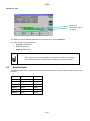
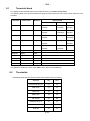
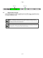
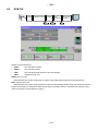
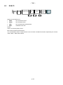
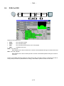
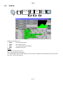
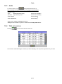
– 7848 – 7848 FIELD STRENGHT METERS USER MANUAL This product contains one or more programs protected under international and US copyright laws as unpublished works. They are confidential and proprietary to Dolby laboratories. Their reproduction or disclosure, in whole or in part, or the production of derivative works there from without the express permission of Dolby Laboratories is prohibited. Copyright 2003-2005 by Dolby Laboratories. All rights reserved. July 2015 – 7848 – Revision follow-up Version / Date Modified chapters Nature of modification 1.0 / July 2015 All Creation of the document p. 2 – 7848 – Thank you for purchasing this SEFRAM product and therefore trusting our company. Our different teams (research department, production, sales department, after-sales service…) are aiming at satisfying your wishes by designing and updating very advanced appliances. To obtain the best performance from this product please read this manual carefully. For more information please contact our different services 04 77 59 01 01 E-mail Sales department: E-mail After-sales: [email protected] [email protected] E-mail Technical support: [email protected] Fax: +33 (0)4 77 57 23 23 Web: www.sefram.fr Copyright Sefram, 2013. All rights reserved. Any total or partial reproduction of this document must be submitted for Sefram written authorisation. p. 3 – 7848 – GUARANTEE Your instrument is guaranteed for one year for labor and parts against any manufacturing defect and/or functioning hazard. This guarantee extends from the delivery date and ends 365 calendar days later. In case of guarantee contract, this will cancel or replace these guarantee conditions hereabove. The guarantee conditions by SEFRAM are available on the website www.sefram.com. The general guarantee conditions should prevail on the following conditions that they sum up. This guarantee does not cover the result of any abnormal use, handling mistake or mistake in the storage conditions outside the defined range. In case of application of the guarantee, the user shall return, at its own expenses, the relevant appliance to our factory: SEFRAM Instruments & Systèmes Service Après-vente 32, Rue Edouard MARTEL BP 55 42009 SAINT-ETIENNE CEDEX 2 And add a description of the observed breakdown to the appliance. The standard supplies provided with the appliance (cables, outlets…), the consumables (batteries …) and the optional supplies (suitcases…) are guaranteed for 3 months against any manufacturing defect. Such items as a suitcase, a LCD screen or a touchpad are guaranteed only for a normal use. The guarantee does not cover wearing, accidental breaks or consecutive to a shock or any abnormal use. The factory options integrated to the appliance are guaranteed for the same duration as the appliance itself. In case of replacement or repair of the product, the remaining guarantee duration shall be: - The remaining duration of the guarantee if the appliance is still under guarantee If the guarantee duration is less than 90 days, the replaced part is guaranteed for 90 days Any replacement part becomes the property of the user and the exchanged parts become the property of SEFRAM. In case of intervention by an insurance company, the product becomes the property of the insurance company upon its exclusive request. Else, it shall remain property of the user. The guarantee covers exclusively the materials manufactured and provided by SEFRAM. Any intervention by the user or any third party without prior authorization by the company voids the guarantee. The user shall be responsible for the return of its appliance to our site. Hence, it shall provide for a conditioning that shall correctly protect the appliance while shipping. It shall subscribe, at its own expenses, any insurance required for the transport. The SEFRAM company reserves the right to refuse any product wrongly conditioned and not to take in charge any break consecutive to the transport. Particular case of the battery: There is a Li-ion battery as a standard equipment of this appliance. It shall not be transported outside the appliance. In no case shall the user replace it. Its replacement in the factory is necessary to check the charge system and the protective securities. What to do in case of malfunction? In case of malfunction or for any advice for use, please contact the technical support by SEFRAM Instruments & Systèmes: 04 77 59 01 01 A technician shall answer you and give you any information required to solve your problem. What to do in case of failure? In case of failure of your appliance, please contact the technical support: 04 77 59 01 01 p. 4 – 7848 – Some advice! Some technical help! SEFRAM Instruments & Systèmes commits itself to help you on the phone about the use of your appliance. Please call or Technical Support: 04 77 59 01 01 Or e-mail: [email protected] We thank you for your trust. METROLOGY The meteorological conditions of your measurement instrument are defined in the specifications of this notice. Climate and environmental conditions restrict the specifications of your Field Strength Measurer (MDC). SEFRAM checks the characteristics of each appliance one by one on an automatic bench during its manufacture. The adjustment and control are guaranteed under conditions of the ISO9001 certification by facilities in connection with the COFRAC (or equivalent in the context of ILAC reciprocity). The specified characteristics are considered stable for a period of 12 months from the first use under normal conditions of use. We recommend a check after 12 months and max. 24 months of use, then every 12 months after 24 months. For any check of the characteristics, the following average climate conditions shall be maintained (23°C+3°C – 50(+20)%RH). The MDC should have been working for 0,5 hour before check. We recommend that you have this control made by our after-sales service (Service Après-Vente) for the best service and preservation of the measuring quality of your instrument. When a MDC returns to SEFRAM, maximum service is provided with internal updating according to the required adjustments and software updates. In case of shift in the characteristics, your instrument shall be adjusted to recover its original characteristics. PACKAGING The packaging of this product is fully recyclable. Its design allows the transport of your instrument under the best possible conditions. Please note that the original packaging should be additionally wrapped in case of transport by air, road or postal. p. 5 – 7848 – TABLE OF CONTENTS 1 2 Important information .......................................................................................................... 9 1.1 Particular precautions .....................................................................................................................................9 1.2 Security instructions .......................................................................................................................................9 1.3 Symbols and definitions .................................................................................................................................9 1.4 Conformity and restrictions of the appliance ................................................................................................10 Quick start-up ..................................................................................................................... 11 2.1 Presentation of the appliance .......................................................................................................................11 2.2 Signal spotting ..............................................................................................................................................12 2.2.1 Checking a terrestrial antenna .............................................................................................................. 12 2.2.2 Installation of a terrestrial antenna ........................................................................................................ 13 2.2.2.1 Use of the spectrum: ......................................................................................................................14 2.2.2.2 Use of the Antenna pointing ..........................................................................................................15 2.2.3 3 4 5 Presentation ....................................................................................................................... 21 3.1 General .........................................................................................................................................................21 3.2 Description of the appliance .........................................................................................................................22 Power-up............................................................................................................................. 23 4.1 Battery ..........................................................................................................................................................23 4.2 Battery charge ..............................................................................................................................................23 4.3 External power supply ..................................................................................................................................24 4.4 Turning the appliance on and off ..................................................................................................................24 Man-machine interface ...................................................................................................... 25 5.1 Content of the screen ...................................................................................................................................25 5.2 Changing name or value ..............................................................................................................................27 5.2.1 Changing inside a table ........................................................................................................................ 27 5.2.2 Change with selection ........................................................................................................................... 28 5.2.3 Change with virtual keyboard ................................................................................................................ 28 5.3 6 Installation of a satellite dish ................................................................................................................. 18 List of setups ................................................................................................................................................29 SATELLITE mode ............................................................................................................... 30 6.1 Check Sat: ....................................................................................................................................................31 6.1.1 Updating satellite................................................................................................................................... 32 6.2 Check Sat function .......................................................................................................................................32 6.1 Checking the aligned satellite ......................................................................................................................34 6.1.1 Recall .................................................................................................................................................... 34 6.2 Autoset : .......................................................................................................................................................35 6.3 Measures – TV – Spectrum:.........................................................................................................................37 6.3.1 6.4 Autolock function ................................................................................................................................... 38 The library page ...........................................................................................................................................38 6.4.1 Creation or modification of setups in the library.................................................................................... 39 6.5 LNB - DiSEqC: .............................................................................................................................................39 6.6 Configuration: ...............................................................................................................................................39 p. 6 – 7848 – 7 TERRESTRIAL mode ......................................................................................................... 40 7.1 Terrestrial check: ..........................................................................................................................................40 7.2 Autoset : .......................................................................................................................................................43 7.3 Measures – TV – Spectrum:.........................................................................................................................45 7.3.1 8 9 AutoLock function.................................................................................................................................. 46 7.4 Terrestrial setup: ..........................................................................................................................................46 7.5 Creation or modification of setups in the library ...........................................................................................47 7.6 Echo / Guard interval:...................................................................................................................................48 7.7 Configuration: ...............................................................................................................................................49 Measures ............................................................................................................................ 50 8.1 Setup modifications ......................................................................................................................................50 8.2 Level measurements ....................................................................................................................................50 8.3 Satellite band ................................................................................................................................................51 8.1 Terrestrial band ............................................................................................................................................52 8.2 Thresholds ....................................................................................................................................................52 8.1 Digital measurements...................................................................................................................................53 8.2 DVB-T/H .......................................................................................................................................................54 8.3 DVB-T2 .........................................................................................................................................................55 8.4 DVB-S et DSS ..............................................................................................................................................56 8.5 DVB-S2.........................................................................................................................................................57 Spectrum analyser ............................................................................................................. 58 10 Image and Sound ............................................................................................................... 59 10.1 Digital TV ..................................................................................................................................................59 10.2 Full screen mode ......................................................................................................................................59 10.3 Audio .........................................................................................................................................................60 10.4 Table of services .......................................................................................................................................60 11 LNB – DiSEqC (Satellite mode) ......................................................................................... 61 11.1.1 Launching ..................................................................................................... Erreur ! Signet non défini. 11.1.2 Switches (satellite remote power supply in expert mode)..................................................................... 63 11.1.3 Positionner (satellite remote power supply in expert mode) ................................................................. 64 11.1.4 DCSS (satellite remote power supply in expert mode) ......................................................................... 65 11.1.4.1 Influence of the DCSS on the spectrum analyzer..........................................................................67 12 Configuration ..................................................................................................................... 68 12.1 Language ..................................................................................................................................................68 12.2 Frequency map .........................................................................................................................................69 12.2.1 Update ................................................................................................................................................... 69 12.3 Factory recovery .......................................................................................................................................69 12.4 Configuration import/export ......................................................................................................................70 13 Software update ................................................................................................................. 71 14 Connection of the appliance to a PC ................................................................................ 72 15 Displayed messages .......................................................................................................... 74 15.1 Alert messages .........................................................................................................................................74 16 Maintenance ....................................................................................................................... 76 p. 7 – 7848 – 17 Technical specifications .................................................................................................... 78 17.1 Technical specifications ............................................................................................................................78 17.2 Digital measurements ...............................................................................................................................79 17.3 Divers ........................................................................................................................................................80 17.1 General specifications ..............................................................................................................................81 17.2 Accessories ..............................................................................................................................................81 17.3 Typical values for measurements .............................................................................................................81 18 CE Declaration ................................................................................................................... 82 p. 8 – 7848 – 1 Important information Please read carefully the following instructions before using your appliance. 1.1 Particular precautions Do not use the product for any other use than specified. Use the provided charger unit to prevent any deterioration of the appliance and guarantee its measurement characteristics. Do not use in a wet environment. Do not use in an explosive environment. In case of failure or for the maintenance of the appliance, only a qualified personal shall be entitled to work on it. In such a case, it is required to use Sefram spare parts. Do not open the appliance: risk of electric shock. You should use the F/F adaptor provided with your measuring instrument. Any other adaptor could damage your appliance and jeopardizes the guarantee. Do not use gloves, stylus or any other object on to the touchscreen. Handle the screen carefully. 1.2 Security instructions For a correct use of the appliance, it is necessary that users abide by the security and use instructions described in this manual. Specific warnings appear all along this manual. In case of need, warning symbols are displayed on the appliance: 1.3 Symbols and definitions Symbols in this manual: Remarque : signale des informations importantes. Key or press zone Window or display zone showing up after the operation achieved p. 9 – 7848 – Symbols on the appliance: Attention: Refer to the manual. Shows a risk of damage for the material connected to the instrument or to the instrument itself. Ground: Grounded accessible parts. Product for recycling. 1.4 Conformity and restrictions of the appliance See chapter EC Declaration of conformity. . p. 10 – 7848 – 2 Quick start-up 2.1 Presentation of the appliance RF connector for use with a F/F adaptor provided with the appliance. Press button ON/OFF Pour mettre l’appareil en marche Pour brancher le signal à analyser Important keys: The 7848 is an appliance with a capacitive touchscreen. This requires a soft handling. No glove and no stylus should be used, so that the triggering should be taken into account. You will recognize the « keys » by their dark grey color (example: the home key: ) You may also access tables by pressing lines (on white or yellow) Welcoming page: HOME Access to the main menu p. 11 – 7848 – Attention: To exit a window like in this example below, press the key: 2.2 Signal spotting The 7848 allows spotting signals in terrestrial or in satellite mode. In the following chapter, we will see how to spot a signal on three types of installation: Checking of a terrestrial antenna (the installation has already been made). Installation of a terrestrial antenna. Installation of a satellite dish. 2.2.1 Checking a terrestrial antenna In this case, the Autoset function allows a scan of the channels that the antenna detects. Plug the cable of your antenna to the 7848 (take care to use an adequate adaptor) Turn on your appliance, then select terrestrial mode : The Home page appears on screen. Press Autoset The scan should range from the E21 to the E69 channels, frequency range Europe (you may reduce the number of channels to scan if you know the range of the emitter where the antenna points at: the scan will be faster) p. 12 – 7848 – Press START. The appliance searches until the end of the scan and turns directly to the Measures page. If no channel has been found, see the next chapter. On this new page, press Prog, select the channel that you want to display. Then you can press TV key to watch the image of the signal. 2.2.2 Installation of a terrestrial antenna To install a terrestrial antenna, you have two methods: Use of the spectrum Use of the terrestrial check p. 13 – 7848 – 2.2.2.1 Use of the spectrum Plug the cable of your antenna to the 7848 (take care to use an adequate adaptor) Turn your appliance on. Press the Measures-TV-Spectrum key Press the Spectrum touch: Access to full SPAN mode Adjust the antenna to get the most powerful signal possible p. 14 – 7848 – You can now display the level, the BER/MER of the signal selected on the same page by pressing the key. 2.2.2.2 Use of the Antenna pointing The appliance gets an antenna pointing mode in order to regulate quickly and easily your terrestrial antenna. To access to the antenna pointing mode menu from the HOME page, press The following page appears : p. 15 – 7848 – Set your emitter name : p. 16 – 7848 – Enter 4 frequencies of the emitter you want to check. You can find many different French transmitters in an Excel file available on the website of SEFRAM (download section, then database transmitters TNT) or by clicking under the following link: http://www.sefram.com/Maj_soft/Canaux_TNT_France_2015.xls Slowly orientate the antenna until hearing the locking melody and getting the best quality p. 17 – 7848 – No transmitter found, bad reception quality → red smiley Average reception quality (< 50%) → orange smiley Good reception quality (> 50%) → green smiley 2.2.3 Installation of a satellite dish Connect the satellite dish to the appliance. Select satellite mode and put into service the Remote power supply by pressing « yes » when the following message appears: Press to access the Check Sat mode (The appliance already includes a list of satellites). p. 18 – 7848 – Select a satelllite like in the example below (here Astra1): Slowly orientate the satellite dish until hearing the locking melody and getting the best quality No found transponder → red smiley Average reception quality (< 50%) → orange smiley Good reception quality (> 50%) → green smiley Reminder: transponder = satellite channel To check if the aimed satellite is the right one: press the NIT key The appliance searches the MPEG NIT table on one of the 4 transponders and displays the name of the satellite: p. 19 – 7848 – Attention: The displayed name depends on the content of the MPEG NIT table. Some distributors provide no (or poor) such table. The displayed information may be wrong. Attention: To identify a satellite, you must be locked on all 4 transponders. (Quality > 0) However, some transponders are regularly modified. See the frequency range of the satellite when a transponder does not seem to work. Some switches or LNB work only with DiSEqC commands. In this case, position the band (OL) and the polarization on DiSEqC at the Configuration page LNB-DiSEqC. (Attention: the Check Sat is slower when using the DISEqC command). p. 20 – 7848 – 3 Presentation 3.1 General -The field strength meter 7848 is an appliance designed for the installation and maintenance of any broadcasting and reception installations of analogical and digital terrestrial television channels or satellites. - The band ranges between 45 MHz and 2200 MHz; this allows accurate measurements on all analogical television standards, FM carrier waves and the various digital standards DVB-T/T2, DVB-S/S2, DSS. - They do Level measurements in average, peak and power according to the selected standard. - Equipped with an efficient Bit Error Rate measurement (various BER, MER), they allow the full validation of digital transmissions DVB-T/T2, DVB-S/S2 and DSS. - The display of Echoes and pre-echoes in DVB-T/T2 gives a complete analysis of the digital signals. - You can display the digital terrestrial or satellite TV under SD or HD. -You can hear digital sound through integrated loudspeakers. - Designed for use on field, they are compact (less than 2 kg, battery included), autonomous (battery pack and quick charger), equipped with a LCD 7’’ touchscreen (capacitive). p. 21 – 7848 – 3.2 Description of the appliance 7’’ capacitive touchscre en high resolution Fastening for straps RF socket with F/F or BNC/F adapter Remote supply light Ethernet socket USB A socket Bouton MARCHE/ARRET Charging indicator light External power socket 15 V 5 A max p. 22 – 7848 – 4 Power-up All the material is checked before shipment and delivered in an adapted packaging. There is no particular unpacking instruction. The appliance is equipped with a Lithium-Ion (Li-ion) battery. It is shipped with the battery loaded. However, if the appliance has remained idle more than one month long, check its charge state and reload if required 4.1 Battery Attention: Any intervention on the battery requires the disassembly of the appliance and should be made by a SEFRAM technician. Use only batteries provided by SEFRAM. Security advice: Do not throw into the fire or heat up the battery pack Do not shunt the parts of the battery: risk of explosion! Do not drill Do not disassemble the battery pack Do not reverse the polarities of the battery This battery pack includes a protective item that should not be damaged or removed Protect the pack from the heat while storing Do not damage the protective sheath of the pack Do not store the appliance in a vehicle under sunlight Used batteries are not for domestic waste; lithium batteries should be recycled. The battery has a 200-charge-discharge cycle life or 2 years. Advice to extend the life of your battery: Avoid deep discharges Do not store the batteries too long without using them Store the battery around 40% loading Do not fully charge or fully discharge the battery before storage. When the battery is almost fully discharged, the appliance will warn “Low battery”, and then will shut off after a few minutes. 4.2 Battery charge To charge the battery inside the appliance: Connect the external power supply provided through the jack plug of the appliance (on the right side) Connect the power supply on the mains The internal charger starts loading the battery; the green lamp lights up. p. 23 – 7848 – Charge the device only when the device is off. Charge the device only with the provided power supply block. The battery is 80%-loaded after 1 hour 50 minutes. The total charge is reached after 2 hours 30 minutes. The autonomy is defined in terrestrial mode with the lighting of the screen decreased, without télé alimentation, interfaces not connected and sound at 10% 4.3 External power supply The appliance works under 15V (1 A) power supply. The power supply block provided is an external power supply too. Only use the power supply block provided with the appliance. Use of another mains block could damage your appliance and would not valid the guarantee. 4.4 Turning the appliance on and off Press the button on the right side of the appliance: The entry page appears on screen. The message “Autotest: running” is shortly displayed, and then disappears. Pressing this button turns the appliance off. The ON/OFF button lights up when the appliance is working. Pressing the ON/OFF button for a long time forces the shut-off of the appliance; proceed this way only in case of necessity. p. 24 – 7848 – 5 Man-machine interface 5.1 Content of the screen 7848 is an appliance with a capacitive touchscreen. This requires a soft handling. No glove and no stylus should be used, so that the triggering should be taken into account. You will recognize the « keys » by their dark grey color (example: the home key: You can also select lines in tables. Selection Access to the selection page terrestrial or satellite The selection page allows changing mode, or in terrestrial, or in satellite: It is possible to come back to the selection page by pressing p. 25 on Home page – 7848 – The Home page allows the navigation through all functions of the appliance: HOME Page in terrestrial mode HOME Page in satellite mode On all pages, we have this informations: Page title Indication of the position of the switch or of the SatCR (position of the slot) Indication of the values Tension and Current of the remote power supply Attention: To exit a window like this one below, you have to press the key p. 26 Indication of the state of the battery – 7848 – To navigate through a table inside a page or a window, a vertical slide appears with arrows to move up and down the table. To move faster, you can slide a cursor with your fingers. Move up through the table Cursor to navigate up or down Move down through the table 5.2 5.2.1 Changing name or value Changing inside a table You can select a setup in the table. In this case, you can validate a setup by pressing the line you want to display. In this example, you change from the TNT-R1 setup to the TNT-R4 in the Measure page: p. 27 – 7848 – 5.2.2 Change with selection When pressing a key, you may have a window with multiple choice. You only have to press the value you want to validate it. This key allows you to cancel and exit this window, like in the example below: In this example, the bandwidth changes from 8 to 6 MHz: 5.2.3 Change with virtual keyboard If you want to enter a name of a number, a window appears with a numeric keypad and a virtual AZERTY keypad: In this keyboard appear keys and exit from this window. to erase, to valid the selected value and the p. 28 key to cancel – 7848 – 5.3 List of setups In order to make easier the recall of data on field, the appliance uses 500 setups in satellite and 500 setups in terrestrial. Example of list of terrestrial setup Example of list of satellite setup A setup is made of: a setup name in 8 characters a satellite/emitter name in 10 characters a frequency a channel number in terrestrial a frequency map in terrestrial a vertical or horizontal polarization in satellite mode a low or high LNB band in satellite mode a standard an analogical mono stereo or NICAM mode in terrestrial a symbol rate under DVB-S, DVB-S2 or DSS According to the terrestrial, cable or satellite band mode and to the standard, some parameters have no influence. The place name may distinguish two distinct emitters, example TF1 Fourvière and TF1 Chambéry. Frequency and channel number are equivalent: a valid channel number has priority over a frequency. The frequency map parameter associated with the setup allows frontiersmen to keep on using channel numbers. Selecting a Setup on a measurement page automatically recalls all information associated with this setup. p. 29 – 7848 – 6 SATELLITE mode When the satellite mode is selected, a message appears with the request of starting Remote power supply of the satellite dish: Once the TV supply activated or not, the HOME page of the satellite mode appears: We will see in this chapter the various menus available from HOME page. p. 30 – 7848 – 6.1 Check Sat: Press to access Check Sat mode. Name and position of the satellite Global quality indication Frequency, polarization, band, level and quality The appliance has 32 possible orbital positions for satellites. It is provided with near of 10 satellites registered. 4 transponders are appended to each satellite. You can select the satellite by pressing « Name and position of the satellite ». To modify a transponder, you must press the corresponding key: Frequency Polarity Symbol rate Standard Active or inactive transponder p. 31 – 7848 – 6.1.1 Updating satellite You can update frequencies of the checks sat by consulting the file PDF posted on-line on the site web of SEFRAM. . You have to modify frequencies, following the previous paragraph and using the file updated monthly on the web site of SEFRAM. http://www.sefram.fr/www/PDF_FR/Sat_PDF.pdf We advise you to check and to update your frequencies every three months. We advise you to check and to update your frequencies every three months 6.2 Check Sat function Procedure: 1/ Connect the satellite dish to the appliance and start it up. 2/ Validate the remote power supply pressing « yes ». 3/ On the Home page, go to the Check Sat mode. Select the satellite to aim at in the list (example ASTRA1) 4/ Slowly orientate the satellite dish until hearing the locking melody and getting the best quality. 5/ Slightly turn the LNB to get the best quality (counter-polarization). You will hear a melody as soon as a first transponder is detected; then, you will hear beeps. These beeps are closer and closer as the quality increases. p. 32 – 7848 – If the appliance is not synchronized on all four transponders, the quality indication is red. If the appliance is synchronized on all four transponders but the reception quality is average, the quality indication is orange. Good reception quality (> 50%) → green smiley. Attention: To identify a satellite, it must be synchronized on all 4 transponders. However, some transponders are regularly modified. See the frequency map of the satellite if a transponder does not seem to work. Some switches or LNB work only with DiSEqC commands. In this case, position the OL and the polarization on DiSEqC in the Configuration page LNB-DiSEqC. (Attention: the Check Sat is slower with DiSEqC commands). p. 33 – 7848 – 6.1 Checking the aligned satellite To check if you have aimed the right satellite, press the NIT key. The appliance searches the MPEG NIT table on one of the 4 transponders and displays the name of the satellite: Attention: The displayed name depends on the content of the MPEG NIT table. Some distributors provide no (or poor) such table. The displayed information may be wrong. 6.1.1 Recall Azimut Position of the satellite dish on the horizontal plane with reference to the north. Measured in degrees. p. 34 – 7848 – Elevation Tilt angle under which the beam from the satellite reaches your antenna. Measured in degrees using what is specified on the stand of the satellite dish. Polarization Rotation required for the LNB from a vertical line. Measured in degrees. 6.2 Autoset : This mode allows an automatic research of setups and to provide information about the current place. You can access it through the key on page Home. A green check shows that the parameter is included in the research. If there is no green check, the parameter will not be taken into account for the research. Attention: The more you select options, the longer the research. p. 35 – 7848 – The table allows the selection of: LNB bands LNB polarizations. The goal is to make researches shorter again Pressing “START” to launch the search. Pressing “Stop” will abort the research The appliance enters automatically the function Measures when the search is ended or when the user stopped the search. Any detected channel will be registered into the fist available setups of the library, starting from the end of the table. New found channels are added one by one into the first available setups of the library, starting from the end of the table p. 36 – 7848 – 6.3 Measures – TV – Spectrum: SPECTRUM mode full screen TV Mode Autolock : Automatic search of setup Mode TV p. 37 – 7848 – 6.3.1 Autolock function This function is design to lock on a digital signal (terrestrial, cable or satellite) You just have to enter the frequency or the channel (for terrestrial), then press AutoLock, The instrument will find automatically in few seconds the digital standard, the modulation type and all other parameters of the signal. Example for satellite low vertical polarization, frequency 12109 MHz : For more information about the page of measures, see chapter Measures. 6.4 The library page By pressing Setup button you can access to the setup list: p. 38 – 7848 – 6.4.1 Creation or modification of setups in the library To create or modify a setup in the library, you have to choose a line in the table. A window appears: Attention: If the line contains a setup, it will be erased. To cancel, press: You may erase the setup from the list by pressing the check to the left of the setup or to the setups you have to delete. Then click the basket and select the deletion of the selected setup: From this window, you can create a satellite setup. To proceed, see chapter 5 Man-machine interface Satellite setup: To enter the type of polarity you want for the setup (high or low, vertical or horizontal) To enter the symbol rate you want for the setup 6.5 LNB - DiSEqC: See dedicated chapter 6.6 Configuration: See dedicated chapter p. 39 – 7848 – 7 TERRESTRIAL mode When terrestrial mode is selected, HOME page of terrestrial mode appears: We will see in the chapter different available menus you can access from HOME page. 7.1 Terrestrial check: The appliance is provided with a terrestrial check in order to regulate quickly and easily your terrestrial antenna. To access to the menu terrestrial check from Home page, press The following page appears : p. 40 – 7848 – Set your emitter name : p. 41 – 7848 – Enter 4 frequencies of the transmitter you want to check. You can find many different French transmitters in an Excel file available on the website of SEFRAM (download section, then database transmitters TNT) or by clicking under the following link: http://www.sefram.com/Maj_soft/Canaux_TNT_France_2015.xls p. 42 – 7848 – Slowly orientate the antenna until hearing the locking melody and getting the best quality No found transponder → red smiley Average reception quality (< 50%) → orange smiley Good reception quality (> 50%) → green smiley Press 7.2 key permits to list the services distributed on the multiplex: Autoset : This mode allows an automatic research of setups and to provide information about the current place. You can access it through the key on page Home. p. 43 – 7848 – A green check shows that the parameter is included in the research. If there is no green check, the parameter will not be taken into account for the research. Attention: The more you select options, the longer is the research. The table allows the selection of: Standards Channel widths The channel range of the research The goal is to make researches shorter by defining at best the settings (example: in France, no DVBT2, band width TNT 8MHz first channel 21, last channel 60) Press “START” to laungh the research. Pressing “Stop” will abort the research. The appliance turns automatically to the Measures page when the research is over or the user has aborted the research. p. 44 – 7848 – Any detected channel will be automatically registered at the end of registered setups: New found channels are added one by one into the first available setups of the library, starting from the end of the table 7.3 Measures – TV – Spectrum: SPECTRUM mode full screen TV mode Autolock : Automatic search of setup Mode TV p. 45 – 7848 – 7.3.1 AutoLock function This function is design to lock on a digital signal (terrestrial, cable or satellite) You just have to enter the frequency or the channel (for terrestrial), then press AutoLock, The instrument will find automatically in few seconds the digital standard, the modulation type and all other parameters of the signal. Example for terrestrial (frequency 611MHz): For more information on measure page, see chapter Measures 7.4 Terrestrial setup: Press allow you to access to the setup list: p. 46 – 7848 – 7.5 Creation or modification of setups in the library To create or modify a setup in the library, you have to choose a line in the table, a window appears: You may erase the setup from the list by pressing the check to the left of the setup or to the setups you have to delete. Then click the basket and select the deletion of the selected setup: From this window, you can create a terrestrial setup. To proceed, see chapter 5 Man-machine interface Terrestrial setup: Under standard DVB-T/H DVB-T2 To enter the place name you want for the setup To enter the name you want for the setup To enter the frequency you want for the setup To enter the channel you want for the setup To enter the frequency band you want for the setup To enter the standard you want for the setup (DVB-T/H in this case) p. 47 – 7848 – 7.6 Echo / Guard interval: Available only for DVBT/H or DVB-T2 standards. Pressing allows you to access to Echo Guard interval measurement. Signal without echo Pressing Signal with echoes and preechoes changes the horizontal scale (distance). Horizontal scale can be set in µs, km or miles by pressing Moving measurement arrow and can be done by screen touch, or by automatic search keys . The end of the guard interval is displayed with a yellow line. Reminder : Remember: In terrestrial TV broadcasting, the received signal on the antenna comes from several possible ways: the echoes. In digital TV DVB-T/H and DVB-T2, these echoes may help or degrade the image according to the time delay between the various signals that reach the antenna. p. 48 – 7848 – The broadcasting norms DVB-T and DVB-T2 define a modulation parameter called "guard interval" where echoes won't disturb the reception. The transmission of digital data (Symbol) is interrupted during the guard interval. A delayed (or advanced) symbol of any shorter duration than the guard interval will not disturb the reception. A delayed (or advanced) symbol of any longer duration than the guard interval will disturb the reception. You have to reduce the level of reception of the echoes by orienting the antenna or by selecting a more directive antenna. The Echo function of the appliance enables you to display possible echoes that disturb the received signal. Yellow line, Main signal Guard interval limit Echos out of interval Pre-echo Measurements form arrow position Relative amplitude in dB and delay in µs (distance in km) from the main signal (0 pulse) can be measured. The yellow line represents the end of the guard interval. Echoes and pre-echoes (pulses) above the yellow line disturb the signal and must be reduced as much as possible. The echoes (pulses) beyond this line disturb the reception and must be as weak as possible. Attention: a high amplitude echo pulse within the guard interval will also disturb the signal quality. 7.7 Configuration: See dedicated chapter p. 49 – 7848 – 8 Measures 8.1 Setup modifications The various parameters are: The name of the setup The frequency of the emitter or transponder (and the true frequency of satellite) The standard and bandwidth for DVB-T/H and DVB-T2 The corresponding channel number for terrestrial mode The symbol rate for the satellite The polarization and the band for the satellite The audio mode for the analogical TV You can shift from terrestrial to satellite mode by going to Home page and pressing : 8.2 Level measurements You can measure levels at a specific frequency with a detection matching the standard. In terrestrial band, for an user socket, the level should be: - between 50 and 66 dBµV under FM - between 35 and 70 dBµV under DVB-T/H, DVB-T2 - between 57 and 74 dBµV in any other case. In satellite band, for an user socket, the level should be: - between 47 and 77 dBµV. p. 50 – 7848 – Example in TNT : Signal level Signal/noise ratio of the signal The appliance makes different measurements according to the current standard. The other possible measurements are: Average measurement Peak measurement Power measurement. The best is to be the closest possible of the green bar without exceeding it. For the MER measure, the value must be superior to the mini threshold. 8.3 Satellite band The following table sums up the measurement types and the frequencies of the audio carrier waves for each standard: Standard porteuse vidéo mesure PAL FM Peak SECAM FM Peak NTSC FM Peak DVB-S Digital Power DSS Digital Power DVB-S2 Digital Power p. 51 – 7848 – 8.1 Terrestrial band The appliance automatically makes level measurements on the Video carrier wave. The following table sums up the measurement types and the frequencies of the audio carrier waves for each standard: Standard BG Video carrier negative, AM DK negative, AM I positive, AM L peak peak peak positive, AM MN Measure peak negative, AM peak DVB-C digital power DVB-T/H digital power DVB-T2 digital power DAB/DAB+ numérique power FM FM average Carrier not modulated average Sound carrier Mono stereo NICAM FM FM DQPSK 5.5 MHz 5.74 MHz 5.85 MHz FM FM DQPSK 6.5 MHz 6.258 MHz 5.85 MHz FM DQPSK 6.0 MHz 6.552 MHz AM DQPSK 6.5 MHz 5.85 MHz FM FM 4.5 MHz 4.72 MHz The appliance displays the level of the Video carrier wave and the C/N ratio. 8.2 Thresholds Predefined thresholds are used to assess if the measurement is pertinent. Standard Min Max Terrestrial analog TV 57 74 DVB-C/C2 57 74 DVB-T/T2 35 70 DAB-DAB+ 35 70 FM, Carrier 50 66 Satellite analog TV 47 77 DVB-S, DSS 47 77 DVB-S2 47 77 p. 52 – 7848 – Seuil min 8.1 Seuil max Digital measurements In digital measurement mode, in addition to the RF level and to the C/N here above, the appliance also displays the various BER (Bit Error Rate), the PER (Packet Error Rate) and the MER (Modulation Error Ratio) under DVB-T/T2, DVB-S/S2 or DSS. “Sync ?” displayed on screen means that the signal is absent or unlocked; check its presence, the modulation parameters, the presence of remote power supply and the LNB and DiSEqC parameters under satellite band. -X The sign < before a value or error rate shows that there is no error but that 10 bits have -8 8 been tested (i.e. <10 means that 10 bits have been tested). p. 53 – 7848 – 8.2 DVB-T/H TUNER DEMODULATEUR VITERBI BERi REED SOLOMON BERo DECODAGE MPEG PER Display of the measures of: BERi: error rate before Viterbi BERo: error rate after Viterbi PER: error rate after Reed Solomon (error rate packet) MER: modulation error rate BERx: bits’ error rate Ratio between the number of false bits / number of transmitted bits during the measurement time PER: ‘paquets’ error rate Ratio between the number of false packets / number of transmitted packets during the measurement time Recall: Under DVB-T/H, a packet is made of 204 octets; a packet is "false" if it includes more than 8 wrong octets (correction by Reed Solomon coding). p. 54 – 7848 – 8.3 DVB-T2 TUNER DEMODULATEUR LDPC BERi BCH BERo DECODAGE MPEG PER Display of the measures of: BERi: error rate before LDPC BERo: error rate after LDPC PER: error rate after BCH (lost packets) MER: modulation error rate Recall: LDPC: Low Density Parity Check BCH: Bose Chauhuri Houquenohem The concatenation Viterbi + Reed Solomon of the correction of DVB-T/H has been replaced by the concatenation LDPC + BCH under DVB-T2. p. 55 – 7848 – 8.4 DVB-S et DSS TUNER DEMODULATEUR VITERBI BERi REED SOLOMON BERo DECODAGE MPEG PER Display of the measures of: BERi : error rate before Viterbi BERo : error rate after Viterbi PER : error rate after Reed Solomon (error rate paquet) MER : modulation error rate BERx : error rate ‘bits’ Ratio between the number of false bits / number of transmitted bits during the measurement time PER : error rate ‘paquets’ Ratio between the number of false packets / number of transmitted packets during the measurement time Recall: Under QPSK (DVB-S) a packet is made of 204 octets; a packet is "false" if it includes more than 8 wrong octets (correction by Reed Solomon coding). Under DSS, a packet is made of 146 octets. p. 56 – 7848 – 8.5 DVB-S2 TUNER DEMODULATEUR LDPC BERi BCH BERo DECODAGE MPEG PER Display of the measures of: BERi : error rate before LDPC BERo : error rate after LDPC PER : error rate after BCH (lost packets) MER : modulation error rate Recall: LDPC: Low Density Parity Check BCH: Bose Chauhuri Houquenohem The concatenation Viterbi + Reed Solomon of the correction of DVB-S has been replaced by the concatenation LDPC + BCH under DVB-S2. p. 57 – 7848 – 9 Spectrum analyser Pressing SPECTRUM gives access to the SPECTRUM ANALYSER function. (graphical representation frequency / amplitude of the present signals in the input of the device) Satellite Terrestrial To swap from between satellite and terrestrial, go to Home page and press you want and return to spectrum , choose the band The input attenuator is automatically tuned according to the level of the signals measured. Filters are automatically selected according to the « Span ». Parameters of the spectrum are: Frequency: value of the frequency where the cursor is, user can enter a frequency value, or increase – decrease the frequency with <> keys Cursor: simply press the area where you want to move or set the cursor Setup: you can select a Setup from internal setup list Channel: use a channel for the spectrum (in terrestrial mode). Reference level: can be modified with updown arrows Span : frequency span around the center frequency p. 58 Frequency range: can be changed using the arrows – 7848 – 10 Image and Sound Pressing the TV zone gives access to the TV function. 10.1 Digital TV The name of the service and its main characteristics are displayed on top left of the screen. 720x576i: picture resolution 720 pixels / line, 576 lines, interlace 25 Hz: frame frequency MPEG-2: picture compression Video Rate 4.106 Mbits/s : instantaneous binary rate of the service Audio MPEG Layer II: sound compression On this page, there are 3 keys at the bottom of the screen; they will be described in the next chapters 10.2 Full screen mode Pressing the key displays the image in full screen; only remain the battery level and the intensity + voltage of the remote power supply: To exit, you only have to touch the screen anywhere. p. 59 – 7848 – 10.3 Audio To set the volume, press an adjustment bar shows up: The instrument can decode the following digital sound formats: MPEG-1 L1/L2 AAC Advanced Audio Coding License Via Licensing HE-AAC High Efficiency AAC License Via Licensing ® Dolby Digital License Dolby Dolby Digital Plus License Dolby ® Made under licence by Dolby laboratories. Dolby and the double-D symbol are trademarks of Dolby Laboratories 10.4 Table of services Pressing gives access to the list of services: This function allows selecting the channel you want to display. You only have to press the line you want. p. 60 – 7848 – 11 LNB – DiSEqC (Satellite mode) This page allows or not the activation of the remote power supply. In this page, there is the possibility to use normal mode or expert mode. Expert mode allows to carry out a larger number of parameters. To access the expert mode, press: Page in simple mode 11.1 Page in expert mode Power ON Setting the remote power supply to satellite: OFF to turn off the remote power supply under satellite measure ON to turn on the remote power supply under satellite measure AUTO to launch automatically the remote power supply in satellite measure mode even after shutting off p. 61 – 7848 – Configuration line in normal mode: - LO1 and LO2 Frequency: LO frequencies low and high band of LNB - LO selection: band commutation on the LNB (22kHz, ToneBurst or DiSEqC) - Polar selection: polarization commutation on the LNB (13/18V or DiSEqC) Configuration line in expert mode: - LO1 and LO2 Frequency: LO frequencies low and high band of LNB - LO selection: band commutation on the LNB (22kHz, ToneBurst or DiSEqC) - Polar selection: polarization commutation on the LNB (13/18V or DiSEqC) - Switch: switch type and position (No, ToneBurst, 22kHz, DiSEqC, Pos A, B, C or D) - Uncommitted: "Uncommitted" switch type and position (No, DiSEqC, Pos 1 to 16) - Positioner: presence of a positioner (Yes / No) - DCSS: Digital Channel Stacking (2 modes SATCR and SCD2 single cable distribution) See chapter Man-machine interface for any change. p. 62 – 7848 – Switches (satellite remote power supply in expert mode) Sat C 4 C om Sat A Sat B Com Sat A 1 3 Sat D 2 2 1 Sat B 11.1.1 2-satellite switch 4-satellite switch * 22 kHz * DiSEqC Committed or Uncommitted * ToneBurst (MiniDiSEqC) *DiSEqC Committed ou Uncommitted Sat D 16-satellites switch * DiSEqC Committed + Uncommitted Sat D Sat C 12 Com Sat A Sat D Com Sat C Sat A Uncommitted p. 63 15 9 Sat B Com Sat A 10 Sat C 16 13 Sat B Com Sat C 7 Sat B Com Sat C Sat A 14 3 Sat D 8 5 Sat B 6 4 Sat B Sat A 1 Sat D 2 11 – 7848 – Switch line Uncommitted line Satellite Position Commande DiSEqC Position 1 Pos A Option A + Position A Pos 1 Input 1 2 Pos B Option A + Position B Pos 1 Input 1 3 Pos C Option B + Position A Pos 1 Input 1 4 Pos D Option B + Position B Pos 1 Input 1 5 Pos A Option A + Position A Pos 2 Input 2 6 Pos B Option A + Position B Pos 2 Input 2 7 Pos C Option B + Position A Pos 2 Input 2 8 Pos D Option B + Position B Pos 2 Input 2 9 Pos A Option A + Position A Pos 3 Input 3 10 Pos B Option A + Position B Pos 3 Input 3 11 Pos C Option B + Position A Pos 3 Input 3 12 Pos D Option B + Position B Pos 3 Input 3 13 Pos A Option A + Position A Pos 4 Input 4 14 Pos B Option A + Position B Pos 4 Input 4 15 Pos C Option B + Position A Pos 4 Input 4 16 Pos D Option B + Position B Pos 4 Input 4 11.1.2 Commande DiSEqC Positionner (satellite remote power supply in expert mode) The appliance sends a DiSEqC command that triggers the rotation of a motorized satellite dish. In this example, the position is 2 (1 to 127 pre-loaded positions in the positionner) If the positionner is on No, it is deactivated See chapter Man-machine interface for any change. p. 64 – 7848 – 11.1.3 DCSS (satellite remote power supply in expert mode) Description: DCSS Digital Channel Stacking system: signal distribution system using frequency transposition. Used in satellite distribution for multiple or single dwelling, with several set top boxes. To give several receptors access to the whole spectrum and all polarizations, you need one coaxial cable per receptor and a suitable installation (multiple LNB, Quattro and multi-switches). The DCSS system allow to feed dwellings with one or more satellites using only one coaxial cable (SCD=SINGLE CABLE DISTRIBUTION). The DCSS is an extension of the DiSEqC protocol that allows the connection of several receptors on only one coaxial cable, no matter the band (H/L) and the polarization (H/V). Functioning: Each satellite receptor uses a fix frequency band (Slot or Port), whose width is (more or less) equal to the width of the transponder. The receptor requires a specific transponder frequency (frequency Ku) via a DiSEqC command. Some equipment on the satellite dish (LNB or switch) moves the requested signal to the center of the selected band (Slot). Then, the mixing equipment adds each user band (Slot) to only one output (up to 32 user bands). Tp1 S a t A - H i g h / H o r i z o n ta l Tp2 S a t A - H i g h / H o r i z o n ta l Tp3 S a t A - L o w / H o r i z o n ta l Tp4 S a t A - L o w / V e r ti c a l S i g n a l su r u n se u l câ b l e Slo t 1 T ra n sp o n d e u rs Ba n d e s u ti l i sa te u rs (S l o t) p. 65 Slo t 2 Slo t 3 Slo t 4 – 7848 – The DCSS mode has priority on all other modes: selection polarization, selection OL, switches committed and uncommitted and positionner. 2 Modes : SATCR : Satellite Channel Router, standard EN50494 (or SCD, Unicable, …) Distribution of the satellite signal with only one coaxial cable to 2, 4 or 8 different receptors. SCD2 : Single Cable Distribution v2, standard EN50607 (or SCD2, Unicable II, JESS) Distribution of the satellite signal with only one coaxial cable to a maximum of 32 different receptors. Using Diseqc 2.0 bi-directionnal possibility to ask current online devices and speed up installation. Mode choice: press DCSS SATCR (EN50494) : SLOT x: active Slot choice CONFIG: access to each slot configuration Slots list, frequencies and switch PosA/PosB INITIALISATIONS : 8 predefined slots ITALY: 4 predefined slots for Italy DETECT: automatic detection of slots (spectrum detect based) p. 66 – 7848 – SCD2 (EN50607) : SLOT x: active Slot choice CONFIG: access to each slot configuration Slots lists, frequencies, switches, PIN codes INITIALISATIONS : 32 predefined slots ALLOCATION : states of the 32 possible slots DETECT : automatic detection of slots (DISEQC2.0 based) 11.1.3.1 Influence of the DCSS on the spectrum analyzer Frequency of the transponder visible at the center of the active slot SatCR mode and active slot Landmarks of the user band (slot) p. 67 Current polarization and band in the active slot – 7848 – 12 Configuration For configuration, go Home page of terrestrial mode or satellite mode, then press configuration 12.1 Language You can select your language by pressing the « flag » (below). Press the flag corresponding to your language: p. 68 – 7848 – 12.2 Frequency map This key allows you to select the terrestrial frequency map of the appliance: 12.2.1 Update See chapter Software update for more details. 12.3 Factory recovery A complete set-up of the appliance under its FACTORY configuration, with confirmation p. 69 – 7848 – Attention: In case of factory recovery, you lose: - the setup library 12.4 Configuration import/export You can make a backup on a USB stick of your setups of your appliance by pushing « « Configuration Export ». And you can import from a USB stick this configuration with the touch “Configuration import”. You can also update checksat configuration available on SEFRAM’s website: http://www.sefram.com/Maj_soft/Sat.csv p. 70 – 7848 – 13 Software update Attention: Take care that the remaining battery life is sufficient (> 30%), else plug the appliance on the mains with the provided adapter. You can easily update the software to get new functionalities. The update requires an USB stick. To achieve the update: - Download the update file 784X_VX.X fichier zip on our website (www.sefram.fr) - Insert a USB stick on your PC - Unzip the file onto the root of the memory stick - Pull the USB stick off from your computer - Turn your appliance on - Go to the terrestrial or to the satellite Home page, . press configuration - Insert the USB stick into the connector of the appliance. -Select Update: Attention : Do not turn the appliance off while updating The updating process lasts ca. 10 minutes. At the end of the update, the appliance asks you to restart the appliance. The software is then loaded into your appliance. Error messages may show up: Do not take them into account. p. 71 – 7848 – 14 Connection of the appliance to a PC The appliance has ETHERNET interface that make it possible to connect directly to a PC. For this type of connection, no driver is necessary. Connect your appliance to your PC by using a crossed ETHERNET cable (available in option with the number 298504246 asking SEFRAM). - Configuration of the connection: Ethernet connection of your appliance to the PC. To change the IP address of your appliance, press With the virtual digital keypad, type the IP address you want, then validate with ENTER The PC software in communication with the appliance must have the same IP address as the appliance, just like in the example below: 784X PC Ethernet network Logiciel PC réglé sur l’adresse 192.168.0.170 p. 72 – 7848 – Attention: If the PC has already been connected to Ethernet (network, modem…), it is necessary to reboot the PC before connecting your appliance. For the Ethernet connection of your appliance to a computer network, see the following scheme: 1) Contact your network administrator to get a free IP address and the subnet mask 2) Type the IP address and the subnet mask in the appliance 3) Type the same IP address and subnet mask in the PC software you’re using p. 73 – 7848 – 15 Displayed messages The appliance may display messages while working. 15.1 Alert messages Low battery: the appliance is about to shut off in a few minutes. Confirmation request for an important action. Remote power supply issue: cable under tension or excess intensity above maximum. p. 74 – 7848 – Messages of the same king may show up; the pop up window is an alert; the corresponding message explains the issue. p. 75 – 7848 – 16 Maintenance This appliance requires some maintenance to meet its requirements and maintain its general characteristics. Consequences BATTERY Recommended periodici- Recommended use ty of controls limit Reduction of the battery life 200 charge / discharge cycles or 2 years STRAPS Breakdown At each use Check the holding of the straps Back Light SCREEN Reduction of visibility Measurement setting / check Erroneous measures Once a year CONNECTIONS Erroneous measures At any measurement 1 years 12 months This "advice" does not engage the responsibility of SEFRAM I.S. It guarantees the best possible use of the characteristics and the preservation of the product. Routine maintenance: The basic maintenance is simply cleaning the outside of the appliance. Any other operation requires a trained personal. Unplug the appliance before any intervention. Do not let water flow inside the appliance: risk of electric shock. Regularly clean the appliance under the following conditions: - use soapy water - never use any product containing petrol, benzene, alcohols that would attack silkscreen printings - wipe out with a soft lint-free cloth - use a solvent-free antistatic product to clean the screen. RF socket : - Make sure there are no specks of copper between the weight and the mass. - Replace periodically the adapter F/F, an adapter in poor condition distorts all the measures. p. 76 – 7848 – INFORMATION ABOUT THE LCD COLOR SCREEN WITH ACTIVE MATRIX Your SEFRAM field strength meter is equipped with a LCD color screen with active matrix. This screen is provided by renowned manufacturers. In the current technical conditions of manufacture, they cannot guarantee 100% good functioning pixels in the display zone. They specify a number of possible defective pixels at the surface of the screen. The SEFRAM quality service has preconditioned the mounting of the screen on your instrument to the respect of the acceptance conditions of the manufacturers. B ZONE A ZONE (Diagonal 60% B) Acceptance criteria: Zone A (central zone): total less than 5 defective pixels, less than 3 contiguous pixels. Zone B (total surface of the screen): less than 9 defective pixels on the whole surface of the screen, with respect of the conditions prevailing in zone A. Is considered as defective any pixel on screen that does not light up or lights up in a different color as expected. The contractual guarantee on your field strength measurer can be exerted only if these criteria are not met, as well at delivery as during the period of guarantee. p. 77 – 7848 – 17 Technical specifications 17.1 Technical specifications Technical specifications Terrestrial band Satellite band Frequencies Range Resolution 45-900 MHz 900-2200 MHz measure 50 kHz, display 1 kHz measure 1MHz, display 1MHz Level measurements Dynamic range 20-120 dBµV (30-120 dBµV for 5-45MHz) 30-110 dBµV Noise floor level 10 dBµV typical 20 dBµV typical Units dBµV Accuracy ±2dB +/- 0.05dB/°C Resolution Measurement Filters Standards 0,1dB 100KHz - 300 kHz - 1MHz 1MHz - 3MHz - 10MHz DVB-T/T2, BG, DK, I, L, MN, carrier DVB-S/S2, DSS PAL, SECAM, NTSC Measures RF level/power, C/N Spectrum Analyser Fast Mode Filters (according to span) Attenuator 350 ms typ. (3 times/s) 100kHz, 300kHz, 1 MHz 1MHz - 3MHz - 10MHz automatic or manual (0 to 55 dB with 5 dB step) Dynamic range (display) Span 60 dB (10 dB/div) 5MHz à full span 1, 2, 5 step Pré-échos /Echos DVBT/T2 Dynamic range DVB-T : 50 dB, -75km +75km ( 8k) DVB-T2 : 50 dB, -75km +75km ( 8k) Units µs, km, miles TV MPEG Digital Multiplex (not coded) MPEG2 SD (définition standard) MPEG4 HD (haute définition H.264) Service table DVB-SI Sound SDT, LCN MPEG-1, MPEG-2, AAC, HE AAC, Dolby® Digital, Dolby® Digital Plus p. 78 – 7848 – 17.2 Digital measurements DVB-T/H Bit Error Rate (BER) CBER (avant Viterbi BERi) VBER (après Viterbi BERo) UNC (paquets perdus PER) Modulation Error Rate(MER) 5 - 35dB Bandwidth 6MHz, 7 MHz, 8 MHz FFT type Constellation 2k, 8k, auto QPSK, 16QAM, 64QAM, auto Viterbi rate 1/2, 2/3, 3/4, 5/6, 7/8, auto Guard interval auto, manual Spectrum inversion auto HP/LP – PLP – Data Slice HP/LP Standards ETS 300-744 DVB-T2 LDPC (BERi) BCH (BERo) FER (frame error PER) Bit Error Rate (BER) Modulation Error Rate(MER) Bandwidth Mode FFT type 5 - 35dB 5MHz, 6MHz, 7 MHz, 8 MHz SISO, MISO, PLP single or multiple 1k, 2k, 4k, 8k, 16k, 32k + extended bandwidth, auto Constellation QPSK, 16QAM, 64QAM, 256QAM, auto Viterbi rate 1/2, 3/5, 2/3, 3/4, 4/5, 5/6, 1/3, 2/5, auto Guard Interval auto Spectrum inversion auto HP/LP – PLP – Data Slice PLP Standards ETS 302-755 DVB-S, DSS Bit Error Rate (BER) CBER (before Viterbi BERi) VBER (after Viterbi BERo) UNC (lost packets PER) Modulation Error Rate(MER) 0-20dB Symbole rate 1 to 45Ms/s Constellation QPSK Viterbi rate 1/2, 2/3, 3/4, 5/6, 6/7, 7/8, auto Spectrum inversion auto Standards ETS 300-421 p. 79 – 7848 – DVB-S2 LDPC (BERi) BCH (BERo) PER Bit Error Rate (BER) Modulation Error Rate(MER) 0-20dB Symbol rate 1 to 45Ms/s Constellation QPSK, 8PSK, 16APSK, 32APSK Modulation CCM, VCM, ACM Viterbi rate 2/5, 1/2, 3/5, 2/3, 3/4, 5/6, 8/9, 9/10, auto Spectrum inversion auto Standards 17.3 ETS 302-307 Divers Remote supply Terrestrial Satellite Tension - 13/18 V 500 mA max DiSEqC - DiSEqC 1.2 control of dish motor switches committed & uncommitted Mini DiSEqC (22kHz) - 22 kHz, ToneBurst SCD /SATCR EN 50494 Single cable satellite distribution - 8 slots max switch committed SCD2 EN 50607 Single cable satellite distribution v2 - 32 slots max switchs committed et uncommitted code PIN Inputs / Outputs RF input 75 Ohms, F (with adaptors) Max permitted voltage Interfaces 48V RMS / 50Hz USB A, Ethernet 10/100baseT (RJ45) jack 5.5 mm 15 V max, 1 A max DC supply input p. 80 – 7848 – 17.1 General specifications Display LCD TFT 7 inch color 16/9, luminosity backlight 500 cd/m², 800x480 dots Touch capacitive External supply Main adaptator 110/230 VAC, with 5,5mm jack, 15 V 1 A Battery Batterie Li-ion 25W Autonomy 2 hours typical, depending of use Charging time 1,5 hour for 80% of capacity Operating temperature -5°C to 45°C Storage temperature -10°C to 60°C EMC and safety NF EN 61326-1(2013) et NF EN 61326-2-1(2013) (class B, basic electromagnetic environment) / NF EN 61010 Dimensions 250 x 165 x 65 mm Weight 1,350 kg (*): the display of encrypted programs is possible for supported encryption, with a valid subscription. 17.2 Accessories Supplied with: main adaptor, user’s manual (CD-ROM), F/F adaptor, protective pouch (mounted) with belt and clip, transportation bag. Optional accessories: 17.3 Car cigar lighter adaptor: ref. 978361000 Carrying bag 784X/781X: ref. 978481000 Luxury backpack réf. 978751000 Sun protector + Rain protector + coat hook ref. 978489000 Rain protector réf. 978489500 Typical values for measurements Values given are indicatives, minimum and maximum for good signal quality Measurements Niveau, puissance (dBµV) mini maxi C/N (dB) BER MER (dB) modulation TV analogique 57 74 > 45 - - - FM 50 66 > 38 - - - - 2K Terrestrial DAB/DAB+ 35 70 DVB-T/H 35 70 E BER < 2 -4 > 26 E VBER < 2 -4 > 26 8K, 64QAM, 1/32, 2/3 E > 22 32K, 256QAM, 1/8, 2/3 E DVB-T2 35 70 > 22 FER < 2 -7 DVB-C 57 74 > 31 BER < 2 -4 > 31 64QAM 47 77 > 15 - - - > 11 QPSK, 3/4 >8 8PSK, 2/3 Satellite Analogue TV E DVB-S, DSS 47 77 > 11 VBER < 2 -4 DVB-S2 47 77 >8 PER < 1 -7 p. 81 E – 7848 – 18 CE Declaration p. 82