1
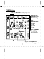
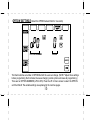
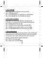
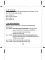
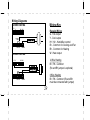
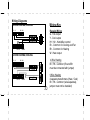
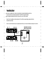
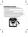
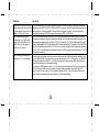
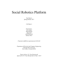
THM701
7 Day Programmable Thermostat
TOUCHSCREEN
TECHNOLOGY
E
L
I
T
E
Features:
Interface s with hea ting/air co nditioning system s for autom atic temperature con trol
Automatic cha nge-ov er for HEATING/COOLING prog rams
Interface s with hum idifier for autom atic hum idity con trol
Sets and displays hou se temperature (°C / °F)
Touchscre en LCD display with bac klight
Displays day, hou r and minute (in 12 or 24 hou r clock format)
Temperature can be set in half d egrees
Copy 1 day ’s prog ram to ano ther day
Automatic ventil ation
Selec table cycle rates for furna ce ON/OFF interva ls
Usage monitor
Fil ter cha nge reminde r
Compatible with millivolt & 24V hea ting system s
Include s mounting hardw are and 3 “AA” batteri es
Table of Contents
Operation and programming guide . . . . . . . . . . . . . . . . . . . . . . . . . . . . . . . . . . . . . . . . . . . . . . . . . 1
Full Display Diagram . . . . . . . . . . . . . . . . . . . . . . . . . . . . . . . . . . . . . . . . . . . . . . . . . . . . . . . . . . . . . . . . . . . . . . . . 2
Symbol Key . . . . . . . . . . . . . . . . . . . . . . . . . . . . . . . . . . . . . . . . . . . . . . . . . . . . . . . . . . . . . . . . . . . . . . . . . . . . . . . 3
Set ºC or ºF . . . . . . . . . . . . . . . . . . . . . . . . . . . . . . . . . . . . . . . . . . . . . . . . . . . . . . . . . . . . . . . . . . . . . . . . . . . . . . . 4
Set Clock . . . . . . . . . . . . . . . . . . . . . . . . . . . . . . . . . . . . . . . . . . . . . . . . . . . . . . . . . . . . . . . . . . . . . . . . . . . . . . . . . 5
Program Heating / Cooling . . . . . . . . . . . . . . . . . . . . . . . . . . . . . . . . . . . . . . . . . . . . . . . . . . . . . . . . . . . . . . . . . . . 6
Set Humidity. . . . . . . . . . . . . . . . . . . . . . . . . . . . . . . . . . . . . . . . . . . . . . . . . . . . . . . . . . . . . . . . . . . . . . . . . . . . . . . 9
Copy Function . . . . . . . . . . . . . . . . . . . . . . . . . . . . . . . . . . . . . . . . . . . . . . . . . . . . . . . . . . . . . . . . . . . . . . . . . . . . . 9
Set Fan / Ventilation / System Mode . . . . . . . . . . . . . . . . . . . . . . . . . . . . . . . . . . . . . . . . . . . . . . . . . . . . . . . . . . . . 10
Override Function . . . . . . . . . . . . . . . . . . . . . . . . . . . . . . . . . . . . . . . . . . . . . . . . . . . . . . . . . . . . . . . . . . . . . . . . . . 11
Hold Function. . . . . . . . . . . . . . . . . . . . . . . . . . . . . . . . . . . . . . . . . . . . . . . . . . . . . . . . . . . . . . . . . . . . . . . . . . . . . . 12
Pre-comfort Recovery . . . . . . . . . . . . . . . . . . . . . . . . . . . . . . . . . . . . . . . . . . . . . . . . . . . . . . . . . . . . . . . . . . . . . . . 13
Usage Monitor . . . . . . . . . . . . . . . . . . . . . . . . . . . . . . . . . . . . . . . . . . . . . . . . . . . . . . . . . . . . . . . . . . . . . . . . . . . . . 13
Filter Change . . . . . . . . . . . . . . . . . . . . . . . . . . . . . . . . . . . . . . . . . . . . . . . . . . . . . . . . . . . . . . . . . . . . . . . . . . . . . . 13
Battery Changing . . . . . . . . . . . . . . . . . . . . . . . . . . . . . . . . . . . . . . . . . . . . . . . . . . . . . . . . . . . . . . . . . . . . . . . . . . . 14
Memory Backup. . . . . . . . . . . . . . . . . . . . . . . . . . . . . . . . . . . . . . . . . . . . . . . . . . . . . . . . . . . . . . . . . . . . . . . . . . . . 15
Backlight . . . . . . . . . . . . . . . . . . . . . . . . . . . . . . . . . . . . . . . . . . . . . . . . . . . . . . . . . . . . . . . . . . . . . . . . . . . . . . . . . 15
Lock Function. . . . . . . . . . . . . . . . . . . . . . . . . . . . . . . . . . . . . . . . . . . . . . . . . . . . . . . . . . . . . . . . . . . . . . . . . . . . . . 15
Option Section . . . . . . . . . . . . . . . . . . . . . . . . . . . . . . . . . . . . . . . . . . . . . . . . . . . . . . . . . . . . . . . . . . . . . . . . . . . . 16
Installation Guide . . . . . . . . . . . . . . . . . . . . . . . . . . . . . . . . . . . . . . . . . . . . . . . . . . . . . . . . . . . . . . . . . . . . . 21
Specifications. . . . . . . . . . . . . . . . . . . . . . . . . . . . . . . . . . . . . . . . . . . . . . . . . . . . . . . . . . . . . . . . . . . . . . . . . . . . . . 34
Troubleshooting . . . . . . . . . . . . . . . . . . . . . . . . . . . . . . . . . . . . . . . . . . . . . . . . . . . . . . . . . . . . . . . . . . . . . . . . . . . . 34
Operation and
Programming Guide
1
Full Display - (includes all icons - for reference only)
LOCK
TABS
STATUS
SYMBOLS
PROGRAM
PERIOD
SYSTEM
MODE
WEEKDAYS
FAN
MODE
TIME
HUMIDITY
2
UP OR DOWN
Symbol Key:
These symbols appear to indicate the following:
COOLING - the air conditioning system is in use.
HEATING - the furnace or heating system is in use.
FAN - the fan is running (FAN symbol will flash).
HUMIDITY - the humidifier is in use.
FILTER CHANGE - the furnace filter should be changed.
BATTERY - the batteries are low and need to be replaced.
LOCK - the thermostat settings are locked and setting cannot be changed.
3
** IMPORTANT - Getting Started **
CELSIUS DEFAULT: Since Celsius (°C) is the default mode no action
is required to use the thermostat in this mode.
(°C or °F) It is VERY IMPORTANT that you choose Fahrenheit (°F) before
you begin using the thermostat. If you proceed to set the clock and program
settings with the default Celsius(°C)and THEN change to the Fahrenheit (°F)
setting; the clock, programs and all system settings will be deleted.
Select ºC or ºF (Celsius or Fahrenheit)
1 Press OPTION for 3 seconds just after batteries are installed.
2 Select Option oP9 with the (left) arrows to choose between °F or °C mode.
3 To choose Fahrenheit select value 1 with the (right) arrows. (1=°F)(0=°C Default)
4 Press OK to exit
(*see option section for more details)
4
SET CLOCK
SET WEEKDAY
Choose 12 or 24 hour clock
1 Press the OPTION tab for 3 seconds.
2 Select Option oP1 with the (left)arrows
3 Choose value with the(right) arrows:
0=12 hour mode (Default)
1=24 hour mode
4 Press OK to exit
(*SEE OPTION Section for more details, and to
select Daylight Savings Time)
Set Time and Weekday
1 Press the Clock area for 3 seconds.
(The clock numbers will begin to flash)
SET TIME
2 Set the time with UP or DOWN arrows.
(Scroll to current hour and minute.)
Note: 12 hour mode is the default
so no action is required to use the
thermostat in this mode.
3 Press OK then select the WEEKDAY
by touching that day.
(The selected weekday will be display
with a flashing underline.)
4 Press OK to exit
Note: Clock operates by the days
of the week but does not track the
date or year.
5
Program Heating and Cooling
This thermostat is equipped with 7 DAY PROGRAMMING. Monday + Tuesday + Wednesday
+ Thursday + Friday + Saturday + Sunday programming with 4 settings per day. This thermostat
is pre-programmed for your convenience or you can set your own programs as desired.
P1: MORNING : This is typically for the morning when you may prefer a warmer temperature.
: This is an energy-savings mode for the time you are away from home. The setting
P2: DAY
can be adjusted to minimize energy consumption.
P3: EVENING : This is for the time you return home and want the house at a comfortable temperature,
typically warmer settings during winter and cooler settings during summer.
: This is the time when you are usually asleep. You may choose to set temperature for
P4: NIGHT
energy savings or comfort as desired.
Note: The program periods
SCHEDULE OF PRE-PROGRAMMED TIME AND TEMPERATURE SETTINGS can be set to the different or
PERIOD
P
TIME
MORNING
DAY
EVENING
NIGHT
P1
P2
P3
P4
6:00am
8:00am
5:00pm
10:00pm
HEAT SETPOINT
o
o
69.0 F (20.5 C)
63.5 oF (17.5 oC)
70.0 oF (21.0 oC)
62.5 oF (17.0 oC)
6
COOL SETPOINT
o
o
77.0 F (25.0 C)
84.0 oF (29.0 oC)
77.0 oF (25.0 oC)
79.0 oF (26.0 oC)
the same temperatures.
For example: Period 1, 2,
o
or 3 can all be set to (22 C)
if you are home all day and
want the temperature to
stay warm, but at night it
o
can be set cooler. (17 C)
PROGRAM Display
1) Select the PROGRAM tab to enter the program mode.
5)Select COPY , then
other weekday(s) to copy
PROGRAM 1-4 settings
3)Select
PROGRAM PERIOD
P1 - Morning
P2 - Day
P3 - Evening
P4 - Night
2)Select any WEEKDAY ,
the selected day
will be underlined
TIME
4)Use the UP
7
or DOWN arrows to set the
start time and temperature for each program period.
Heating / Cooling Program
1 Select PROGRAM tab to display program settings.
- HEAT TEMP (displays heating temperature settings / adjust with up or down arrows)
- COOL TEMP (displays air conditioning temperature settings / adjust with up or down arrows)
- PROGRAM (touch the program area to sequence between program periods P1, P2, P3 or P4)
- CLOCK AREA (displays the time the program period will start )
2
3
4
5
6
Select any WEEKDAY to view its settings: (MON, TUE, WED, THU, FRI, SAT, SUN)
Select (P1=MORNING PERIOD) to set it’s program settings.
Adjust the HEAT / COOL / CLOCK (temperature and start time) settings with the UP / DOWN arrows.
REPEAT above steps to set the times and temperatures for P2 (DAY), P3 (EVENING) and P4 (NIGHT).
To accept settings select OK, to undo settings press select CANCEL. To continue to program the rest
of the week by each day press the PROGRAM tab again or select COPY and then weekday(s) to copy
the 4 program periods to the selected day(s).
Note: After one day is programmed, you can copy all 4 of that day’s program settings to
any other day using the COPY program function. (see the Copy Function section)
Note: Heat and Cool temperature settings must be at least 3 degrees different.
Note: Select AUTO on system settings to ensure heating and cooling programs will run
automatically.
8
Humidifier Control
1
2
3
4
Verify the humidifier is correctly wired to the thermostat. (see installation guide or contact an electrician)
Ensure HEAT mode is selected.
Touch the HUMIDITY display area, and then set the humidity level using the UP / DOWN arrow keys.
To de-activate the humidifier setting, scroll DOWN to it’s lowest setting until “OFF” (oF%) displays.
The humidifier will automatically turn on if the relative humidity is lower than the set humidity level.
Humidity is set in increments of 5%.
The humidity level can be set from 20% to 70%.
Note: The humidifier control only functions when thermostat is in HEAT mode.
Note: Humidity is a manual setting which remains constant (it is not pre-programmable).
Copy Program Function
(MON, TUE, WED, THU, FRI, SAT, SUN)
This thermostat can copy program settings from one day to another using the COPY function.
1 Select the PROGRAM folder, then select the weekday you wish to copy. (This day will disappear)
2 Select COPY, then select the weekday(s) the settings are to be copied to. (days will be underlined)
4
*(Multiple days can be chosen, i.e. You can copy 1 day’s settings to all 6 other days in a single
operation. All four period settings (P1, P2, P3,P4) will be copied.)
3 To accept copied settings select OK, to undo settings select CANCEL.
9
Fan Control / Automatic Ventilation
Select FAN/AUTO (for automatic control of the fan)
In heating mode, the fan is controlled by the heating equipment.
In cooling mode, the fan is controlled by the cooling equipment.
Select FAN/ON (for the fan to run continuously)
Select FAN/VENT (for automatic ventilation). (The fan will run five minutes per hour, this
ventilation feature is designed for better air flow, without heating or cooling being applied.)
Note: When the fan is running, the FAN
symbol will flash.
System Mode: AUTO / HEAT / OFF / COOL
AUTO - The heating or cooling system will activate according to pre-programed temperature settings.
HEAT - The system is in HEAT mode and furnace or heating system is activated.
OFF - If the thermostat is in the OFF mode, both the heating and cooling systems will be turned off,
and all programs and settings will be disabled.
COOL - The system is in COOL mode and air conditioner or cooling system is activated.
When the heating or cooling systems are ON, the following symbols will flash.
will flash when the heating system is running.
will flash when the cooling system is running.
10
.
Temporary OVERRIDE
This function will maintain a constant temperature until the next program period starts.
If the system is in AUTO mode, only the currently active mode (heat or cool) setting will be changed.
1 On the MAIN tab press the UP / DOWN arrows beside the preset temperature to override the temperature.
(*The OVERRIDE tab will display to indicate the OVERRIDE function is active.)
(*The new temperature will then remain the same until the next program starts.)
2 To undo select CANCEL
1
OVERRIDE UNTIL (Hour)
1
2
3
4
If you wish to select a specific OVERRIDE OFF time (different than the start time of the next program
period) you may select the OVERRIDE UNTIL feature.
On the MAIN tab press the UP / DOWN arrows beside the preset temperature to change the temperature.
(The OVERRIDE tab will display)
Then select the OVERRIDE tab (UNTIL will display above the clock)
Set the OFF time with the CLOCK arrows.
(*The new temperature will now remain the same until the selected OFF time.)
To undo select CANCEL.
*Note: When these features are activated the words OVERRIDE or UNTIL are displayed on the LCD.
Therefore it is not necessary to select OK to activate these features.
11
HOLD Function
This function will maintain a constant temperature indefinitely.
1 Select the HOLD tab (The HOLD symbol will flash to indicate HOLD is activated)
2 Press the UP / DOWN arrows beside the preset temperature to change the temperature.
*(The new temperature will then remain the same indefinitely until you select CANCEL)
HOLD UNTIL (Day)
If you wish to select a specific day to turn the HOLD feature off (rather than having it lasting indefinitely)
you may select the HOLD UNTIL day feature.
2 Select the HOLD tab (The HOLD symbol will flash to indicate HOLD is activated)
Select the HOLD tab again, (HOLD UNTIL will display below the weekdays) then select a WEEKDAY.
*(The selected day will be underlined)
*(The new temperature will then remain the same until midnight of the selected weekday)
3 To undo select CANCEL.
1
*Note: When these features are activated the words HOLD or HOLD UNTIL are displayed on the LCD.
Therefore it is not necessary to select OK to activate these features.
12
Pre-comfort Recovery
This thermostat is equipped with a ‘Pre-comfort Recovery’ system that will activate the heating or cooling in
advance of the actual set program time so that the room will be at the desired temperature at the start of the
program time.
It is normal for the system to be activated earlier than the actual set program time (up to one hour).
The Pre-comfort Recovery can be disabled if desired. (See "Option Section”)
Usage Monitor
(USAGE/ACCU TAB)
The thermostat tracks the total number of hours the heating and cooling system is running.
Press the USAGE tab once to view the hours of usage PER DAY. (The USAGE tab then displays ACCU)
Then press any weekday to view the usage hours for that day.
Press the ACCU tab again to view the USAGE THIS WEEK. (Accumulated hours starting from Monday)
Press the ACCU tab again to view the 7 DAY USAGE. (Accumulated hours of today plus the last 6 days)
Press CANCEL any time to exit the usage mode.
- USAGE TODAY automatically resets itself daily at midnight.
- USAGE THIS WEEK automatically resets itself at the end of the week. (Midnight, Sunday)
Filter Change
The FILTER CHANGE indicator will display on the LCD screen when the system "ON" time (HEAT, COOL
or FAN) has accumulated to approximately a certain number of hours. It is an indication that the furnace filter
should be changed at this time. The default number of hour is 1000 hours but the hour amount can be changed
in the OPTIONS tab. (See "Option Section”)
13
Changing Batteries
When the battery symbol
is visible on the LCD screen, it indicates that the batteries are running low and
need to be replaced. However, it is recommended that the batteries be replaced every year, even if the
battery symbol does not appear.
To replace batteries:
Select OFF to turn the thermostat to the OFF mode.
Remove the thermostat from its mounting plate (back cover) carefully.
Remove the old batteries and install new ones very quickly.
Replace the thermostat to its original position.
NOTE: If new the batteries are inserted within 20 seconds of removing the old ones, the existing time will not
be cleared. Otherwise, the display may show an incorrect time and the clock will have to be set again.
14
Memory backup for the Programs and Thermostat Settings
The thermostat has built-in permanent memory which stores all the set programs and thermostat
settings if ever the batteries go completely dead or if the batteries are removed from the thermostat
for an extended period of time. When the batteries are re-inserted, the thermostat will recall and
resume with all the stored programs and settings. However, the clock itself will have to be reset.
Backlight
The backlight helps you to clearly see the thermostat display at night. However, frequent
adjustments with the backlight enabled will reduce your battery life. To disable backlighting see
the “Option Section”.
Lock Function
To prevent accidental tampering of the programs or to clean the unit, select LOCK for 3 seconds.
The LOCK symbol will flash to indicate the LOCK function is active.
To unlock the keypad, select LOCK for 3 seconds again until a normal display returns.
15
OPTION SETTINGS (Select the OPTION tab and hold for 3 seconds)
OPTION NUMBER
VALUE
The thermostat has a number of OPTIONS which the user can change. (NOTE: *Adjust these settings
before programming the thermostat, because changing certain options will erase all programming.)
There are ten OPTION NUMBERS (oP0 to 0P9). Press the UP or Down arrows to select the OPTION
and the VALUE. The variable settings are explained in the next few pages.
16
Optional Settings (Select the OPTION tab and hold for 3 seconds)
1) (oP0) - Daylight Savings Time
2) (oP1) - Clock Format 12 or 24 hour
3) (oP2) - LCD Backlight
4) (oP3) - Key Click / Freeze Warning
5) (oP4) - Pre-comfort Recovery
6) (oP5) - Heat Cycle Rate
7) (oP6) - HE/HG Fan Mode Selection (heating)
8) (oP7) - Filter Change Reminder
9) (oP8) - System Type
10) (oP9) - °C or °F Display
1) (oP0) - Daylight Savings Time
Daylight savings time “ON” will advance your clock by one hour.
Value 0=DST OFF (Default)
Value 1=DST ON
2) (oP1) - Clock Format 12 or 24 hour
Choose value “1” for 24 hour clock. (12 hour is the default so no selection is required)
Value 0= 12 hour clock (Default)
Value 1= 24 hour clock
17
3) (oP2) - LCD Backlight
Select the amount of time the LCD light will stay on after a key is selected
Value 0= OFF (Backlight is always off)
Value 1= 2 Seconds (Backlight stays on for 2 seconds after a key is pressed) (Default)
Value 2= 8 Seconds (Backlight stays on for 8 seconds after a key is pressed)
4) (oP3) - Key Click / Freeze Warning
Choose whether or not a key click sound is audible when you press the LCD screen.
Choose whether or not a warning sounds if your ever home reaches freezing temperatures.
Value 0= OFF (Silent: Buzzer and clicks never sound)
Value 1= CLICK ON (Key click sound enabled, warning sound disabled) (Default)
Value 2= WARNING ON (Freeze warning buzzer enabled, key click sound disabled)
Value 3= CLICK AND WARNING ON (Both click and freeze warning buzzer enabled)
5) (oP4) - Pre-comfort Recovery
The thermostat will activate the furnace to begin blowing heat before a program period time begins.
This feature ensures that a comfortable temperature will have been reached at the very beginning
of the program period. The pre-comfort cycle will range between a half hour to one full hour,
depending on the number of degrees of temperature change required.
Value 0= OFF (Pre-comfort recovery disabled)
Value 1= ON (Pre-comfort recovery enabled)(Default)
18
6) (oP5) - Heat Cycle Rate
Choose the furnace heat cycle (the total ON/OFF intervals that the furnace completes in one hour)
Value 0= OFF (Cycle rate disabled - fixed span)
Value 1= 3 cycles / hour
Value 2= 4 cycles / hour (Default)
Value 3= 6 cycles / hour
Value 4= 8 cycles / hour
7) (oP5) - HE/HG Fan Mode Selection
Depending on your home’s heating system, you may need to change the HE/HG setting
for the fan operation.
Value 0=HG Mode (Use this setting for gas or oil-fired furnaces. This setting allows the fan
operation to be controlled by the heating system, not the thermostat.
This is the correct setting for most systems. (Default)
*Humidifier will not activate the fan
Value 1= HE Mode (You must use this setting for electric furnace heating systems. With this
setting, the thermostat will turn the fan on immediately with the heating system.
*Humidifier will not activate the fan
Value 2= HG Mode (In this HG mode the humidifier will activate the fan)
Value 3= HE Mode (In this HE mode the humidifier will activate the fan)
19
8) (oP7) - Filter Change Reminder
Choose how many hours the furnace will be in use before filter change indicator will display.
Value 0= Disabled (Filter change icon will never display)
Value 1= 500 hours
Value 2= 1000 hours (Default)
Value 3= 2000 Hours
Value 4= 4000 Hours
9) (oP8) - System Type (Conventional Furnace)
Depending on your home’s heating system, you may need to choose between a conventional
furnace system or an alternative system.
Value 0= Conventional (Default)
Value 1= Alternative (O/B wire active when COOLING)
Value 2= Alternative (O/B wire active when HEATING)
10) (oP9) - °C or °F Display
Since Celsius (°C) is the default mode, no action is required to use the thermostat in this mode.
Select value “1” for Fahrenheit, before setting any other thermostat settings.
Value 0= Celsius (Default)
Value 1= Fahrenheit
20
Installation
Guide
21
Installation Guide
Introduction
This thermostat can replace common residential thermostats and it is designed for use with most
central heating and air conditioning systems that use low voltage control. Please see
compatibility chart on the next page for more details.
3 “AA” size batteries required (included)
Built-in protection timing for the air conditioner compressor
Warning
We recommend consulting a licenced electrician to ensure the safe installation of your thermostat.
The only way to guarantee wiring safety is to have a qualified professional on site.
* NOT COMPATIBLE WITH ANY HIGH VOLTAGE 120/240 VOLT CIRCUIT.
22
Compatibility
Generally, equipment with low voltage control is compatible with Heating/Cooling Programmable
Thermostats.
Compatible with Thermostat
Yes
Yes
Some models
Yes
Some models
Yes
Yes
Yes
No
No
No
System Type
Gas - Standing Pilot
Gas - Electronic Ignition
Gas - Fire Boiler
Gas - Millivolt System
Oil - Fire Boiler
Oil - Fire Furnace
Electric Furnace
Electric Air Conditioner
Baseboard Electric Heater (120/240V)
Heat Pump/Single-Stage
Heat Pump/Multi-Stage
* NOT COMPATIBLE WITH ANY HIGH VOLTAGE 120/240 VOLT CIRCUIT.
23
Installation
The following tools may be required for installation:
(
Power drill with a 3/16” bit
) Screwdriver
( If necessary, to drill holes on the wall )
Masking Tape
(To wrap the exposed wires temporarily and to label
the disconnected wires)
Wire Stripper/Cutter
Level
(If necessary, to level the thermostat)
3 “AA” size batteries (included)
(If necessary, to strip the wires)
- “AA” SIZE +
- “AA” SIZE +
- “AA” SIZE +
24
Choosing a Location for the new Thermostat
Thermostat should be mounted:
Approximately 5’ (1.5 m) from floor.
Near or in a frequently used room, preferably on an inside partitioning wall.
On a section of wall without pipes or duct-work.
Thermostat should NOT be mounted:
Near a window, on an outside wall, or next to a door leading outside.
Exposed to direct light or heat from a lamp, sun, fireplace, or other temperature-radiating objects
which may cause false readings.
Near or in direct airflow from heat registers and air conditioners.
Near concealed pipes and chimneys.
In areas with poor air circulation, such as behind a door or in an alcove.
Note: Do not operate the cooling system when outside temperature is below 10°C (50°F) to avoid
damaging the compressor.
25
Replacing the Old Thermostat
Test the system to make sure that your heating and cooling systems are working properly before
installation. If either does not work, contact a heating/air conditioning service person to fix the
problem before installation.
TURN OFF POWER to system at the furnace, or at the fuse/circuit breaker panel.
Carefully unpack your new thermostat and mounting plate; save package of screws, instructions and
receipt. Remove cover from old thermostat. If it does not snap off when pulled firmly from the bottom,
check for a screw used to secure the cover. Loosen screws holding thermostat to the wall and lift
away the thermostat.
Wiring
NOTE: WIRING COLORS ARE NOT ALWAYS STANDARDIZED, SO IT IS VERY IMPORTANT TO
LABEL ALL WIRES ACCORDING THE LETTER DESIGNATION ON YOUR OLD THERMOSTAT.
(The wires are usually designated 'W', 'Y', 'G', 'RH', 'RC', 'W' ,'B', ‘O' or humidistat wires.)
Disconnect wires from old thermostat or sub-base. As you disconnect each wire, use masking tape
to label it with the old terminal designation.
Take care not to let the wires fall back into the wall or let the ends of the wires touch one another.
If there is an extra wire that is not connected to your old thermostat, then you won't need to connect
it to the new thermostat.
26
** IMPORTANT - Getting Started **
Remove the thermostat backplate and install 3 “AA” size batteries (included).
Ensure the batteries are installed in the correct direction.
Remove Backplate
Reset Button: to restore default settings
Back
Front
Install 3 AA Batteries
27
Installing the Batteries and Selecting the Display in °C or °F
Please consult page 27 for guidelines on how it install the 3 “AA” size batteries (included) into the
thermostat following the polarity as marked. The LCD screen will immediately show the room temperature.
Please consult page 4 for instructions on how to select °C or °F.
CELSIUS DEFAULT: Since Celsius (°C) is the default mode no action is required to use the
thermostat in this mode.
(°C or °F) It is VERY IMPORTANT that you choose Fahrenheit (°F) before you begin using the
thermostat. If you proceed to set the clock and program settings with the default Celsius(°C)and
THEN change to the Fahrenheit (°F)setting: the clock, programs and all system settings will be deleted.
(SOFT RESET)If the display does not appear after installing the batteries, press the reset button on the
back of the unit.
(HARD RESET)To clear all system settings and return the unit to factory defaults press
and hold the LOCK tab, and at the same time, press and release the RESET button on the back of
the unit.
SEE OPTIONS SECTION: The thermostat has a number of OPTIONS which the user can change.
(NOTE: *Adjust these settings before programming the thermostat, because changing certain
options will erase all programming.)
28
Wiring Diagrams
Wiring Key
2-WIRE HEATING
G
Y
H2 H1
Regular Wiring
G - Fan output
Y - Cool output
H1 / H2 - Humidifier control
Rc - Common for Cooling and Fan
Rh - Common for Heating
W - Heat output
(OPTIONAL)
JUMPER
Rc Rh
W/ B/O
3-WIRE HEATING
G
Y
2 Wire Heating
Rc / Rh - Common
(Rc and Rh jumper is optional)
H2 H1
Rc Rh
3 Wire Heating
Rc / Rh - Common (Rc and Rh
must be connected with jumper)
W/ B/O
29
Wiring Diagrams
Wiring Key
4-WIRE HEATING/COOLING
G
Y
Regular Wiring
G - Fan output
Y - Cool output
H1 / H2 - Humidifier control
Rc - Common for Cooling and Fan
Rh - Common for Heating
W - Heat output
H2 H1
Rc Rh
W/ B/O
5-WIRE HEATING/COOLING
G
Y
4 Wire Heating
Rc / Rh - Common (Rc and Rh
must be connected with jumper)
H2 H1
Rc Rh
W/ B/O
30
5 Wire Heating
2 separate transformers (Heat / Cool)
Rc / Rh - Common (wire separately,
jumper must not be installed)
Humidifier Wiring
To wire a humidifier, the 2 wires connecting the original humidistat need to be
connected to the 2 terminals marked 'H1' and 'H2' on the thermostat.
The original humidistat should be removed or set to 'OFF' position.
Note: The 2 humidifier control terminals 'H1' and 'H2' are electrically isolated from the
Heat/Cool terminals.
Note: H1 and H2 terminals are non polarized and there is no function difference between H1 and H2.
G
Y
Humidistat should be
OFF or disconnected
H2 H1
Rc Rh
W/ B/O
31
Connecting the Wires to the Terminals
Wall
Connect the previously labeled wires to the corresponding
terminals, matching the designations. Use a screwdriver to
loosen the terminal, wrap the wires around the terminal then
tighten to securely fasten the wires. Make sure the
wires do not touch or short-circuit with other terminals.
Through Hole
Back cover
Wall
Depending on your heating/cooling equipment, you may
need to connect between 2 to 7 wires to the thermostat.
If you have two ‘R’ wires, then connect each wire to its
corresponding terminal and remove the JUMPER between
the RC and RH terminals.
If you are unsure of the connections please consult a certified
electrician for the safe installation of your thermostat.
Wires
Back cover
Terminals
32
Mounting the Back Cover of the Thermostat
The back cover should be mounted horizontally with the terminals on the top.
Thread the existing wiring through the big center hole from the back and set the back cover
horizontally on the wall.
Select two appropriate mounting holes and mark the locations with a pencil. If necessary, use a
level to make sure the thermostat is leveled.
Remove the back cover from the wall and drill two 3/16” holes in the marked screw positions.
Insert the wall anchors into the holes completely. If necessary, use a hammer to tap-in lightly.
Mount the back cover to the wall using the two screws. Make sure the metal terminals are on the top.
Attach the thermostat body to the back cover (that is already mounted on the wall) by
carefully aligning the two pieces and pressing firmly until they snap together.
LEVEL
Back cover
Mark the
locations
with a pencil
33
Specifications:
Number of programs: 7 Day with 4 settings per day
Temperature setting range: 5 – 35°C (41 – 95°F)
Temperature display range: 0 – 50°C (32 – 122°F)
Humidity setting range: 20 to 70%
Humidity display range: 20 to 95%
Battery: 3 x “AA” size batteries
TROUBLESHOOTING GUIDE
PROBLEM
SOLUTION
LCD screen is blank.
- Check if the batteries are installed correctly.
- Check if the batteries are fresh and of the correct type.
- Select RESET button on the back of the unit.
Battery symbol (
- This is an indication that the batteries are running low. Replace with fresh alkaline batteries.
Note: We recommend to have the batteries replaced at least once a year even if the battery symbol is
not flashing.
) is flashing.
Heat will not come on.
1) Check and ensure that the thermostat is set to the HEAT or AUTO mode.
2) Check and ensure that the set temperature is higher than the current (room) temperature.
3) You may have to wait up to 5 minutes before the heat will turn on. The thermostat has a built-in time
delay to prevent undesirable on/off sequences.
4) After a 5-minute wait, the heating should now be on. Whenever the heating system is running, the
symbol will be animated.
34
PROBLEM
SOLUTION
Heat will not come on but the
symbol is animated.
1) Check if the furnace switch and/or pilot flame is turned on, as it may have been turned off.
2) Allow several minutes for the heating system to heat up and the fan to activate. Most heaters will heat
up the system for a short while before warm air can be ventilated by the fan. Also check that the
HE/HG setting is set correctly. (see optional settings)
3) If the heat still does not come on, check the wiring installation again.
Air conditioning will not come on.
1) Check and ensure that the thermostat is set to the COOL or AUTO mode.
2) Check and ensure that the set temperature is lower than the current (room) temperature.
3) You may have to wait up to 5 minutes before the air conditioning will turn on. The thermostat has a
built-in time delay to protect the air conditioner compressor from undesirable on/off sequences.
4) After a 5-minute wait, the air conditioning should now be on. Whenever the cooling system is
running, the
symbol will be animated.
1) Check if the air conditioning system’s main switch is turned on, as it may have been turned off.
2) Wait several minutes for the air conditioning system to activate. If the air conditioning still does not
come on, check the wiring installation again.
Air conditioning will not come on
but the
symbol is animated.
The thermostat turns the heating
or cooling systems on before my
programmed set times.
This is normal if the Pre-comfort Recovery system is enabled. The Pre-comfort Recovery will activate
the heating/cooling in advance of the actual programmed set time so that the room will be at the
desired temperature at the start of the program time. You may disable this feature in the
“option section”.
Heating system seems to cycle
too often.
Check and ensure that you have selected a Cycle Rate that matches your particular heating system.
The default is set at Cr-3 for gas or oil forced air systems. If you find it still cycling too often, you may
wish to try a slower cycle rate or disable the cycling. When disabled, the thermostat will operate at a
fixed span of (plus or minus) ±0.5°C (±1.0°F). For example, if the programmed temperature is set at
20°C (68°F), the thermostat will turn the heat on if the current (room) temperature falls below 19.5°C
(67°F) and turn the heat off when the current (room) temperature reaches 20.5°C (69°F).
35
PROBLEM
SOLUTION
Thermostat is set on AUTO mode,
but the thermostat does not seem
to automatically change-over from
HEAT to COOL or vice-versa.
The thermostat has a built-in safeguard time delay of 30 minutes to prevent undesirable change-over
sequences from HEAT to COOL or COOL to HEAT. For example, if the thermostat was just running the
cooling system, it will take at least 30 minutes before it changes to heating. You may override this
manually by pressing MODE to change the operation to HEAT or COOL only.
While adjusting the program
temperature in the HEAT mode,
the program temperature in the
COOL mode also changes by
itself; and/or vice-versa
This will occur when you set the HEAT and COOL program temperatures fairly close to one another.
To prevent a mistake or overlap in temperature settings, the thermostat automatically restricts the two
temperature settings from getting within 3°C (6°F) of one another. The COOL temperature setting will
always be at least 3°C (6°F) higher than the HEAT temperature setting. For example, if the initial COOL
program temperature was set at 24°C (75°F) and you decide to adjust the HEAT program temperature
to 24°C (75°F), the thermostat will automatically push the COOL program temperature up to 27°C (81°F)
to prevent overlapping.
Cannot change the thermostat
scale from °C to °F or vice-versa.
Selecting the temperature scales is a one-time start-up process. After the first battery installation, you
must HARD reset the thermostat and choose the desired display in °C or °F. Otherwise, you CANNOT
change the temperature scale (°C or °F) later on unless you perform another HARD reset which will
clear all the programs and thermostat settings.
To perform a HARD reset and select °C or °F, first press reset and hold the LOCK key at the same time.
The LCD screen will blank out momentarily. Once the display reappears, then release the LOCK
key. To select °F, select option 10 in the Optional Settings tab. For °C, do not press any buttons and
wait until the temperature display stops flashing.(°C is the default setting)
36
Limited 5-year Repair Warranty
This product carries a five (5) year repair warranty against defects in workmanship and materials.
This product is not guaranteed against wear or breakage due to misuse and/or abuse.
If the product is defective, return it, with a dated proof of purchase, to the retailer from which you purchased it
Attention:
IT IS STRONGLY RECOMMENDED TO HAVE A CERTIFIED ELECTRICIAN ON SITE TO ENSURE THE SAFE
INSTALLATION OF YOUR THERMOSTAT. The manufacturer assumes no responsibility for improper wiring,
or any resulting damages. Installation by a non-professional automatically voids the warranty.
Note: shipping and handling for returns is not included under this warranty.
Customer Service Centre
1-888-468-6876
* NOT COMPATIBLE WITH ANY HIGH VOLTAGE 120/240 VOLT CIRCUIT.
37