1
EE 209 Lab 1 – Sound the Alarm
1 Introduction
In this lab you will design, implement and then test a simple logic circuit emulating
a home alarm system. You will use the Digital Trainer board for this lab and may
work in teams of two, turning in one answer sheet for the both of you.
2 What you will learn
This lab is intended to teach you the basics of building and wiring digital circuits.
You will also be asked to think of a test strategy to ensure your circuit works as
specified in the following English-language description.
3 Background Information and Notes
The Alarm System: The alarm system to be designed has the following inputs.
Input
N
W
D
G
X
Description
The system enable (i.e. the on/off state of the alarm system).
1 = Enabled / 0 = Disabled)
Window sensors = 1 indicates all windows are secured/closed
Door sensors = 1 indicates all doors are secured/closed
Garage sensor = 1 indicates the garage door is secure
Exiting input. 1 indicates that you are currently leaving the house
and thus an open door or window should not cause the alarm to
turn on. 0 indicates that you are out of the house.
The only output of the alarm system should be a single bit, A, which will be 1 if the
alarm is activated and 0 otherwise. The alarm should activate if the system is
enabled, you are not exiting, and the house is not secure. The house is
considered secure if all the sensors (windows, doors, garage) are 1.
Implementation: For this lab you will implement your design on the provided
Digital Trainer Board. Read the Digital Trainer board user manual and/or follow
along as your instructor describes the features and operation of the board. Some
important do’s and don’ts will be highlighted.
4 Prelab
Watch the two videos linked on the course website for this lab.
Last Revised: 8/26/2015
1
EE 209 Lab 1 - Sound the Alarm
5 Procedure
1. Given the description of the alarm system in section 3, design a logic circuit to
implement the alarm system. Use only inverters and the 2-input AND and OR
gates (no NOR and NAND for now). For inputs and outputs use the following
mapping:
Logical
Input/Output
N
X
W
D
G
A
Trainer Board I/O Device
SW1
SW4
PB1
PB2
PB3
LED5
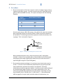
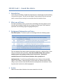
Since the push buttons (PB1-PB3) output a 1 by default this means the window,
door, and garage values are secure by default. When we press the buttons it
will produce a ‘0’ indicating someone has opened or broken the window, door
or garage. This is reiterated in Figure 1.
Vdd
PB1-PB3 =
W, D, or G
‘1’ (secure)
by default
GND
(Vss)
Figure 1 - PB outputs producing the W, D, and G values
When implementing your circuit, note that you only have 2-input gates
available. However, you should be able to easily handle this shortcoming by
manipulating your design slightly (think about how you could construct a 3input AND gate using two 2-input AND gates.)
2. Once you have wired your design, it is now time to test it and make sure it is
correct. To test this circuit exhaustively would require trying every possible
input combination and ensure the output is as expected. How many
combinations would this approach require? Instead, use your understanding of
the intended logic design to devise a list of input combinations (a.k.a. test
vectors) that provide high satisfaction that your design is operating correctly
(e.g. {N,X,W,D,G}=>A = {0,0,0,0,1}=>0, {1,0,0,1,0}=>1,…). Use the attached
table on page 6 to list your (near) minimal number of combinations, the
2
Last Revised: 8/26/2015
EE 209 Lab 1 - Sound the Alarm
expected value of A and the actual value of A produced by your circuit when
you plug in the given combination. If you find mismatches between your
expected and actual outputs, go back to your circuit and make sure you’ve
implemented it correctly.
Hint: At the very least we need to prove the alarm is off under normal
conditions but also turns on under all the necessary cases. Think about the gate
types you are using and how each input should affect the output (e.g. an OR
gate should output ‘1’ when only a single input is ‘1’ even if all other inputs are
‘0’). Somewhere around six to eight combinations (vectors) should suffice.
6 Review
1. How many combinations would be necessary to exhaustively test your design?
2. Provide a short justification (a paragraph) explaining how you chose your
minimal set of test vectors and why they provide a high degree of satisfaction
that your design works under all conditions.
Last Revised: 8/26/2015
3
EE 209 Lab 1 - Sound the Alarm
4
Last Revised: 8/26/2015
EE 209 Lab 1 - Sound the Alarm
7 Lab Report
Name: ___________________________________
Due: _____________
Score: ________
(Detach and turn this sheet along with any other requested work or printouts)
Turn in the following items:
1. Original schematic of your working design.
2. Instructor Signoff of working design: _____________
Continued on next page.
Last Revised: 8/26/2015
5
EE 209 Lab 1 - Sound the Alarm
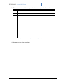
3. Table of test vectors with the expected and actual output values for each.
N
X
W
D
G
Expected A
Actual A
Table 1 - List your minimal set of test input combinations, expected, and actual output values
4. Answers to the review questions.
6
Last Revised: 8/26/2015
EE 209 Lab 1 - Sound the Alarm
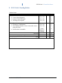
8 EE 101 Lab 1 Grading Rubric
Student Name: _______________________________________________________
Item
Outcome
Score Max.
Design
Yes / No
1
Correct Alarm Equation
Yes / No
2
Correct Circuit Schematic
Yes
/
No
3
Working circuit signoff
Review Questions
Exhaustive Combinations
Near Minimal number of test vectors with correct
expected values
Justification is reasonable
Yes / No
Yes / No
1
1
Good /
Adequate /
Missing
2
SubTotal
10
Total
10
Late Deductions (-1 pts. per day)
Open Ended Comments:
Last Revised: 8/26/2015
7