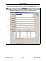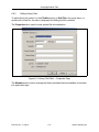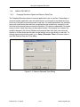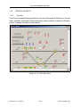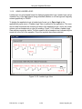
1
abcd ACCUTRACK PRODUCT SOLUTIONS Computer-Aided Application Programming Environment (CAAPE) User Manual Copyright © 2006, 2007, 2008, 2009, 2013, 2014, 2015 Alstom Signaling Inc. WARNING READ MANUAL BEFORE USE Read this manual before using this software. Keep this manual in a safe location for future reference. Failure to follow the instructions presented in this manual can degrade the safety performance of the train control system resulting in death or serious injury due to train collision or derailment. User Manual P2512A abcd ACCUTRACK PRODUCT SOLUTIONS Computer-Aided Application Programming Environment (CAAPE) User Manual Copyright © 2006, 2007, 2008, 2009, 2013, 2014, 2015 Alstom Signaling Inc. WARNING READ MANUAL BEFORE USE Read this manual before using this software. Keep this manual in a safe location for future reference. Failure to follow the instructions presented in this manual can degrade the safety performance of the train control system resulting in death or serious injury due to train collision or derailment. User Manual Alstom Signaling Inc. P2512A, Rev. J, August 2015, Printed in U.S.A. LIST OF EFFECTIVE PAGES P2512A, Computer-Aided Application Programming Environment (CAAPE) User Manual ORIGINAL ISSUE DATE: March 2006 CURRENT REVISION AND DATE: Rev J, August 2015 PAGE CHANGE OR REVISION LEVEL Cover Aug/15 Title page Aug/15 Preface Aug/15 i through xvi Aug/15 1-1 through 1-12 Aug/15 2-1 through 2-8 Aug/15 3-1 through 3-6 Aug/15 4-1 through 4-8 Aug/15 5-1 through 5-16 Aug/15 6-1 through 6-4 Aug/15 7-1 through 7-68 Aug/15 8-1 through 8-50 Aug/15 9-1 through 9-10 Aug/15 10-1 through 10-6 Aug/15 11-1 through 11-64 Aug/15 12-1 through 12-14 Aug/15 13-1 through 13-60 Aug/15 P2512A, Rev. J, Aug/15 Alstom Signaling Inc. P2512A, Rev. J, Aug/15 Alstom Signaling Inc. PREFACE NOTICE OF CONFIDENTIAL INFORMATION Information contained herein is confidential and is the property of Alstom Signaling Inc. Where furnished with a proposal, the recipient shall use it solely to evaluate the proposal. Where furnished to a customer, it shall be used solely for the purposes of inspection, installation, or maintenance. Where furnished to a supplier, it shall be used solely in the performance of the contract. The information shall not be used or disclosed by the recipient for any other purposes whatsoever. VPI® and iVPI® are registered trademarks of Alstom Signaling Inc. All other trademarks referenced herein are trademarks of their respective owners. FOR QUESTIONS AND INQUIRIES, CONTACT CUSTOMER SERVICE Address: Alstom Signaling Inc. 1025 John Street West Henrietta, NY 14586 USA Website: www.alstomsignalingsolutions.com Email: [email protected] Phone: 1-800-717-4477 P2512A, Rev. J, Aug/15 Alstom Signaling Inc. REVISION LOG Revision Release Date Description of Change Author Checker Approver 0(A) March 2006 Original issue MS JM NI 1(B) September 2007 MS JM NI 2(C) May 2008 Updated to add WIU and iVPI MS JM NI 3(D) October 2009 Updated to add new iVPI boards, CSEX4, VPI CAA -010 MS JM NI 4(E) January 2013 Updated to add new iVPI detail SG KW NI F November 2013 Updated to include FSSVT clarification SG KW MS G February 2014 Added Section 4.5. SG KW MS H August 2014 Updated warnings SG KW MS April 2015 Added a new Section 1; added/revised warnings; new Section 5.5; removed reference to WIU SG KW MS August 2015 Updated warnings; updated Tracker references (obsolete); updated Section 9.2.2 SG KW MS I J P2512A, Rev. J, Aug/15 Added CPU II board Alstom Signaling Inc. ABOUT THIS MANUAL This manual contains the basic information needed to understand how to use Alstom’s Computer-Aided Application Programming Environment software package (referred to as either CAAPE or the CAAPE). The information in this manual is arranged into sections. The title and a brief description of each section follow: Section 1 – SAFETY PRECAUTIONS: This section contains safety precautions applicable to CAAPE. Section 2 – GENERAL: This section gives general information on manual intent, content, and conventions. Section 3 – INTRODUCTION: This section introduces the features of CAAPE and describes system requirements. Section 4 – GETTING STARTED: This section describes the basics of installing and preparing to use CAAPE. Section 5 – CAAPE PROJECTS: This section describes how to use CAAPE projects to organize and manage application data. Section 6 – GENERAL RULES AND TECHNIQUES: This section describes some general rules for entering application data. Section 7 – USING CAAPE GRAPHICS: This section provides information on using CAAPE’s graphical editing tools to enter application data. Section 8 – USING APPLICATION FILES: This section describes how to use application input, output and report files. Section 9 – APPLICATION CHANGE PROCESS: This section describes the process of making changes to an existing application, especially as it applies to Vital applications. Section 10 – CONFIGURATION CONTROL: This section describes the various configuration control features available in CAAPE. Section 11 – USING THE GRAPHIC SIMULATOR: This section describes how to use the Graphical Simulator tool. Section 12 – CAAPE FILE STRUCTURE: This section is a guide to the directory structure of CAAPE and the files that CAAPE uses. Section 13 – SIMULATOR REFERENCE: This section gives detailed information on some simulator file formats. P2512A, Rev. J, Aug/15 Alstom Signaling Inc. P2512A, Rev. J, Aug/15 Alstom Signaling Inc. MANUAL SPECIAL NOTATIONS In Alstom manuals, signal word panels are used to convey special safety and informational messages. Danger, Warning and Caution Signal Word Panels include a safety alert symbol in addition to the signal word, whereas Notice and Safety Instructions Signal Word Panels include only the signal word. This is the safety alert symbol. It is used to alert of potential physical injury hazards. Obey all safety messages that follow this symbol to avoid possible injury or death. Signal Word Panel Definition DANGER Indicates a hazardous situation, which, if not avoided, will result in death or serious injury. WARNING Indicates a hazardous situation, which, if not avoided, could result in death or serious injury. CAUTION Indicates a hazardous situation, which, if not avoided, could result in minor or moderate injury. NOTICE Indicates a situation which could result in property damage or information considered important, but not hazard-related. SAFETY INSTRUCTIONS P2512A, Rev. J, Aug/15 Indicates specific safety-related instructions or procedures. Alstom Signaling Inc. P2512A, Rev. J, Aug/15 Alstom Signaling Inc. TABLE OF CONTENTS Topic Page SECTION 1 – Safety Precautions . . . . . . . . . . . . . . . . . . . . . . . . . . . . . . . . . . . . . . . 1-1 1.1 Safety Precaution Matrix. . . . . . . . . . . . . . . . . . . . . . . . . . . . . . . . . . . . . . 1-1 1.2 Safety Precautions . . . . . . . . . . . . . . . . . . . . . . . . . . . . . . . . . . . . . . . . . . 1-2 SECTION 2 – General . . . . . . . . . . . . . . . . . . . . . . . . . . . . . . . . . . . . . . . . . . . . . . . . 2.1 About This Manual . . . . . . . . . . . . . . . . . . . . . . . . . . . . . . . . . . . . . . . . . . 2.2 Safety . . . . . . . . . . . . . . . . . . . . . . . . . . . . . . . . . . . . . . . . . . . . . . . . . . . . 2.3 Intended Audience . . . . . . . . . . . . . . . . . . . . . . . . . . . . . . . . . . . . . . . . . . 2.4 Document Conventions. . . . . . . . . . . . . . . . . . . . . . . . . . . . . . . . . . . . . . . 2.5 Common Abbreviations and Glossary . . . . . . . . . . . . . . . . . . . . . . . . . . . 2.6 Related Publications . . . . . . . . . . . . . . . . . . . . . . . . . . . . . . . . . . . . . . . . . 2-1 2-1 2-2 2-3 2-3 2-4 2-7 SECTION 3 – Introduction . . . . . . . . . . . . . . . . . . . . . . . . . . . . . . . . . . . . . . . . . . . . 3.1 What is CAAPE?. . . . . . . . . . . . . . . . . . . . . . . . . . . . . . . . . . . . . . . . . . . . 3.2 Theory of Operation . . . . . . . . . . . . . . . . . . . . . . . . . . . . . . . . . . . . . . . . . 3.2.1 Applications. . . . . . . . . . . . . . . . . . . . . . . . . . . . . . . . . . . . . . . . . . . . 3.2.2 System Software and Application Data. . . . . . . . . . . . . . . . . . . . . . . 3.2.3 CAAPE Projects and their Contents . . . . . . . . . . . . . . . . . . . . . . . . . 3.2.4 Using CAAPE . . . . . . . . . . . . . . . . . . . . . . . . . . . . . . . . . . . . . . . . . . 3.2.5 CAA Versions . . . . . . . . . . . . . . . . . . . . . . . . . . . . . . . . . . . . . . . . . . 3.3 System Requirements. . . . . . . . . . . . . . . . . . . . . . . . . . . . . . . . . . . . . . . . 3.3.1 Computer and Operating System . . . . . . . . . . . . . . . . . . . . . . . . . . . 3.3.2 Additional Hardware . . . . . . . . . . . . . . . . . . . . . . . . . . . . . . . . . . . . . 3.3.3 Additional Software . . . . . . . . . . . . . . . . . . . . . . . . . . . . . . . . . . . . . . 3-1 3-1 3-1 3-1 3-2 3-2 3-3 3-4 3-5 3-5 3-6 3-6 SECTION 4 – Getting Started . . . . . . . . . . . . . . . . . . . . . . . . . . . . . . . . . . . . . . . . . . 4.1 Introduction . . . . . . . . . . . . . . . . . . . . . . . . . . . . . . . . . . . . . . . . . . . . . . . . 4.2 Preparing to Install CAAPE. . . . . . . . . . . . . . . . . . . . . . . . . . . . . . . . . . . . 4.2.1 Installation Serial Number. . . . . . . . . . . . . . . . . . . . . . . . . . . . . . . . . 4.2.2 Installation Prerequisites. . . . . . . . . . . . . . . . . . . . . . . . . . . . . . . . . . 4.3 Installing CAAPE. . . . . . . . . . . . . . . . . . . . . . . . . . . . . . . . . . . . . . . . . . . . 4.4 Starting and Exiting Caape . . . . . . . . . . . . . . . . . . . . . . . . . . . . . . . . . . . . 4.5 User Interface Elements . . . . . . . . . . . . . . . . . . . . . . . . . . . . . . . . . . . . . . 4.6 Setting User Preferences . . . . . . . . . . . . . . . . . . . . . . . . . . . . . . . . . . . . . 4.7 Help and Tutorials. . . . . . . . . . . . . . . . . . . . . . . . . . . . . . . . . . . . . . . . . . . 4-1 4-1 4-1 4-1 4-1 4-2 4-2 4-3 4-6 4-8 SECTION 5 – CAAPE Projects . . . . . . . . . . . . . . . . . . . . . . . . . . . . . . . . . . . . . . . . . 5-1 P2512A, Rev. J, Aug/15 i Alstom Signaling Inc. TABLE OF CONTENTS Topic Page 5.1 Overview . . . . . . . . . . . . . . . . . . . . . . . . . . . . . . . . . . . . . . . . . . . . . . . . . . 5-1 5.1.1 Projects and their Locations . . . . . . . . . . . . . . . . . . . . . . . . . . . . . . . 5-1 5.1.2 Systems and Applications. . . . . . . . . . . . . . . . . . . . . . . . . . . . . . . . . 5-1 5.1.3 Project Data Entry. . . . . . . . . . . . . . . . . . . . . . . . . . . . . . . . . . . . . . . 5-2 5.1.4 Project Contents and Files . . . . . . . . . . . . . . . . . . . . . . . . . . . . . . . . 5-2 5.1.5 Viewing Project Data. . . . . . . . . . . . . . . . . . . . . . . . . . . . . . . . . . . . . 5-3 5.2 Creating a Project . . . . . . . . . . . . . . . . . . . . . . . . . . . . . . . . . . . . . . . . . . . 5-6 5.3 Opening an Existing Project . . . . . . . . . . . . . . . . . . . . . . . . . . . . . . . . . . . 5-9 5.4 Importing a Project . . . . . . . . . . . . . . . . . . . . . . . . . . . . . . . . . . . . . . . . . . 5-9 5.5 Importing an AFTC5 Track Circuit XML File to a VPI II/iVpi Hardware System . . . . . . . . . . . . . . . . . . . . . . . . . . . . . . . . . . . . . . . . . . 5-10 5.6 Setting Project Options . . . . . . . . . . . . . . . . . . . . . . . . . . . . . . . . . . . . . . 5-13 5.7 Generating Data for MMS . . . . . . . . . . . . . . . . . . . . . . . . . . . . . . . . . . . . 5-14 5.8 Archiving Project Files . . . . . . . . . . . . . . . . . . . . . . . . . . . . . . . . . . . . . . 5-15 5.9 Changing Project Directories . . . . . . . . . . . . . . . . . . . . . . . . . . . . . . . . . 5-16 SECTION 6 – General Rules and Techniques . . . . . . . . . . . . . . . . . . . . . . . . . . . . 6.1 System and Application Names . . . . . . . . . . . . . . . . . . . . . . . . . . . . . . . . 6.2 Symbols . . . . . . . . . . . . . . . . . . . . . . . . . . . . . . . . . . . . . . . . . . . . . . . . . . 6.2.1 Symbol Naming Rules . . . . . . . . . . . . . . . . . . . . . . . . . . . . . . . . . . . 6.2.2 Symbol Declaration and Usage . . . . . . . . . . . . . . . . . . . . . . . . . . . . 6.2.3 Subroutine Arguments . . . . . . . . . . . . . . . . . . . . . . . . . . . . . . . . . . . 6.2.4 Arrays . . . . . . . . . . . . . . . . . . . . . . . . . . . . . . . . . . . . . . . . . . . . . . . . 6.2.5 PERMONE/PERMZERO . . . . . . . . . . . . . . . . . . . . . . . . . . . . . . . . . 6.2.6 Symbol Table . . . . . . . . . . . . . . . . . . . . . . . . . . . . . . . . . . . . . . . . . . 6.3 I/O Wiring . . . . . . . . . . . . . . . . . . . . . . . . . . . . . . . . . . . . . . . . . . . . . . . . . 6.4 Using Wildcard Characters . . . . . . . . . . . . . . . . . . . . . . . . . . . . . . . . . . . . 6-1 6-1 6-1 6-1 6-2 6-3 6-3 6-3 6-3 6-4 6-4 SECTION 7 – Using CAAPE Graphics . . . . . . . . . . . . . . . . . . . . . . . . . . . . . . . . . . . 7.1 Graphical Work Flow. . . . . . . . . . . . . . . . . . . . . . . . . . . . . . . . . . . . . . . . . 7.2 Creating and Managing Graphical Components. . . . . . . . . . . . . . . . . . . . 7.2.1 Component Types. . . . . . . . . . . . . . . . . . . . . . . . . . . . . . . . . . . . . . . 7.2.2 Component Files. . . . . . . . . . . . . . . . . . . . . . . . . . . . . . . . . . . . . . . . 7.2.3 Creating a Component . . . . . . . . . . . . . . . . . . . . . . . . . . . . . . . . . . . 7.2.4 Setting Component Description . . . . . . . . . . . . . . . . . . . . . . . . . . . . 7.2.5 Removing Components . . . . . . . . . . . . . . . . . . . . . . . . . . . . . . . . . . 7-1 7-1 7-3 7-3 7-3 7-4 7-6 7-6 P2512A, Rev. J, Aug/15 ii Alstom Signaling Inc. TABLE OF CONTENTS Topic Page 7.2.6 7.2.7 Renaming Components . . . . . . . . . . . . . . . . . . . . . . . . . . . . . . . . . . 7-6 Editing Components . . . . . . . . . . . . . . . . . . . . . . . . . . . . . . . . . . . . . 7-6 7.3 Editing Hardware Components . . . . . . . . . . . . . . . . . . . . . . . . . . . . . . . . . 7-7 7.3.1 Setting General Hardware Properties . . . . . . . . . . . . . . . . . . . . . . . . 7-7 7.3.2 Adding Hardware Modules . . . . . . . . . . . . . . . . . . . . . . . . . . . . . . . . 7-8 7.3.3 Setting Module Properties. . . . . . . . . . . . . . . . . . . . . . . . . . . . . . . . 7-11 7.3.4 Adding Module Boards . . . . . . . . . . . . . . . . . . . . . . . . . . . . . . . . . . 7-12 7.3.5 Editing Boards. . . . . . . . . . . . . . . . . . . . . . . . . . . . . . . . . . . . . . . . . 7-14 7.3.6 Using the Grid Control . . . . . . . . . . . . . . . . . . . . . . . . . . . . . . . . . . 7-15 7.3.7 Opening the Variable List Dialog . . . . . . . . . . . . . . . . . . . . . . . . . . 7-15 7.3.8 Using the Find/Replace Dialog . . . . . . . . . . . . . . . . . . . . . . . . . . . . 7-16 7.3.9 Upgrading Boards . . . . . . . . . . . . . . . . . . . . . . . . . . . . . . . . . . . . . . 7-17 7.3.10 Setting Board Relationships . . . . . . . . . . . . . . . . . . . . . . . . . . . . . . 7-17 7.3.11 Printing . . . . . . . . . . . . . . . . . . . . . . . . . . . . . . . . . . . . . . . . . . . . . . 7-19 7.3.12 iVPI VSP Board and Zone Controller . . . . . . . . . . . . . . . . . . . . . . . 7-19 7.3.13 Ordering of Vital Messages. . . . . . . . . . . . . . . . . . . . . . . . . . . . . . . 7-22 7.4 Editing Message Components . . . . . . . . . . . . . . . . . . . . . . . . . . . . . . . . 7-23 7.4.1 Source and Destination Names . . . . . . . . . . . . . . . . . . . . . . . . . . . 7-23 7.4.2 Using the Grid Control . . . . . . . . . . . . . . . . . . . . . . . . . . . . . . . . . . 7-24 7.4.3 Printing . . . . . . . . . . . . . . . . . . . . . . . . . . . . . . . . . . . . . . . . . . . . . . 7-24 7.5 Editing Logic Components . . . . . . . . . . . . . . . . . . . . . . . . . . . . . . . . . . . 7-25 7.5.1 Overview of Statement Types. . . . . . . . . . . . . . . . . . . . . . . . . . . . . 7-27 7.5.1.1 Boolean Equations . . . . . . . . . . . . . . . . . . . . . . . . . . . . . . . . 7-27 7.5.1.2 Comments . . . . . . . . . . . . . . . . . . . . . . . . . . . . . . . . . . . . . . 7-29 7.5.1.3 Group Records. . . . . . . . . . . . . . . . . . . . . . . . . . . . . . . . . . . 7-29 7.5.1.4 Function Statements . . . . . . . . . . . . . . . . . . . . . . . . . . . . . . 7-29 7.5.2 Caret Positioning. . . . . . . . . . . . . . . . . . . . . . . . . . . . . . . . . . . . . . . 7-29 7.5.3 General Editing Techniques . . . . . . . . . . . . . . . . . . . . . . . . . . . . . . 7-30 7.5.3.1 Using Hotkeys and the Hotkey Bar . . . . . . . . . . . . . . . . . . . 7-30 7.5.3.2 Using the Logic Toolbar . . . . . . . . . . . . . . . . . . . . . . . . . . . . 7-30 7.5.3.3 Navigating the Logic View Window . . . . . . . . . . . . . . . . . . . 7-31 7.5.3.4 Selecting Logic Items . . . . . . . . . . . . . . . . . . . . . . . . . . . . . . 7-31 7.5.3.5 Using Popups. . . . . . . . . . . . . . . . . . . . . . . . . . . . . . . . . . . . 7-32 7.5.3.6 Opening Logic Items . . . . . . . . . . . . . . . . . . . . . . . . . . . . . . 7-32 7.5.3.7 Using Undo . . . . . . . . . . . . . . . . . . . . . . . . . . . . . . . . . . . . . 7-32 P2512A, Rev. J, Aug/15 iii Alstom Signaling Inc. TABLE OF CONTENTS Topic Page 7.5.3.8 Using Cut and Paste . . . . . . . . . . . . . . . . . . . . . . . . . . . . . . 7.5.3.9 Using Drag and Drop . . . . . . . . . . . . . . . . . . . . . . . . . . . . . . 7.5.3.10 Changing the Appearance of the Logic Editing Screen . . . . 7.5.4 Inserting Statements . . . . . . . . . . . . . . . . . . . . . . . . . . . . . . . . . . . . 7.5.5 Editing Statement Properties . . . . . . . . . . . . . . . . . . . . . . . . . . . . . 7.5.6 Editing Boolean Equations . . . . . . . . . . . . . . . . . . . . . . . . . . . . . . . 7.5.6.1 Adding and Inserting Branches . . . . . . . . . . . . . . . . . . . . . . 7.5.6.2 Drawing Branches . . . . . . . . . . . . . . . . . . . . . . . . . . . . . . . . 7.5.6.3 Inserting Variables . . . . . . . . . . . . . . . . . . . . . . . . . . . . . . . . 7.5.6.4 Editing Variable Data . . . . . . . . . . . . . . . . . . . . . . . . . . . . . . 7.5.6.5 Selecting Equation Data. . . . . . . . . . . . . . . . . . . . . . . . . . . . 7.5.6.6 Deleting Equation Data . . . . . . . . . . . . . . . . . . . . . . . . . . . . 7.5.6.7 Transferring Equation Data . . . . . . . . . . . . . . . . . . . . . . . . . 7.5.6.8 Variable Selection List . . . . . . . . . . . . . . . . . . . . . . . . . . . . . 7.5.6.9 Setting Internal Variable Types . . . . . . . . . . . . . . . . . . . . . . 7.5.6.10 Setting Relay States. . . . . . . . . . . . . . . . . . . . . . . . . . . . . . . 7.5.6.10.1 Equation Variables . . . . . . . . . . . . . . . . . . . . . . . . . . . . . . . 7.5.6.10.2 Equation Results. . . . . . . . . . . . . . . . . . . . . . . . . . . . . . . . . 7.5.6.10.3 Compatibility with Older Versions of CAAPE . . . . . . . . . . . 7.5.7 Deleting Statements . . . . . . . . . . . . . . . . . . . . . . . . . . . . . . . . . . . . 7.5.8 Commenting/Uncommenting Statements . . . . . . . . . . . . . . . . . . . . 7.5.9 Using Find, Replace and Go To . . . . . . . . . . . . . . . . . . . . . . . . . . . 7.5.10 Defining Constants . . . . . . . . . . . . . . . . . . . . . . . . . . . . . . . . . . . . . 7.5.11 Declaring Internal Variables . . . . . . . . . . . . . . . . . . . . . . . . . . . . . . 7.5.12 Cut & Paste and Drag & Drop of Text Data . . . . . . . . . . . . . . . . . . 7.5.13 Opening the Variable List Dialog . . . . . . . . . . . . . . . . . . . . . . . . . . 7.5.14 Printing The Logic . . . . . . . . . . . . . . . . . . . . . . . . . . . . . . . . . . . . . . 7.6 Editing Link Protocol Components . . . . . . . . . . . . . . . . . . . . . . . . . . . . . 7.6.1 Printing . . . . . . . . . . . . . . . . . . . . . . . . . . . . . . . . . . . . . . . . . . . . . . 7.7 Using the Variable List Dialog. . . . . . . . . . . . . . . . . . . . . . . . . . . . . . . . . 7.8 Creating and Managing Graphical Systems . . . . . . . . . . . . . . . . . . . . . . 7.8.1 Basic Concepts of Graphical Systems . . . . . . . . . . . . . . . . . . . . . . 7.8.1.1 Component Linking . . . . . . . . . . . . . . . . . . . . . . . . . . . . . . . 7.8.1.2 Make Files and Build Names . . . . . . . . . . . . . . . . . . . . . . . . 7.8.2 Creating a System . . . . . . . . . . . . . . . . . . . . . . . . . . . . . . . . . . . . . P2512A, Rev. J, Aug/15 iv 7-32 7-33 7-33 7-34 7-36 7-36 7-36 7-36 7-36 7-37 7-37 7-37 7-38 7-38 7-38 7-39 7-39 7-40 7-40 7-41 7-41 7-41 7-44 7-44 7-45 7-45 7-45 7-46 7-46 7-47 7-49 7-49 7-49 7-49 7-50 Alstom Signaling Inc. TABLE OF CONTENTS Topic Page 7.8.3 7.8.4 7.8.5 7.8.6 7.8.7 7.8.8 7.8.9 Adding Components to the System . . . . . . . . . . . . . . . . . . . . . . . . Entering Application Revision History . . . . . . . . . . . . . . . . . . . . . . . Saving and Closing the System . . . . . . . . . . . . . . . . . . . . . . . . . . . Renaming a System . . . . . . . . . . . . . . . . . . . . . . . . . . . . . . . . . . . . Deleting a System. . . . . . . . . . . . . . . . . . . . . . . . . . . . . . . . . . . . . . Opening an Existing System. . . . . . . . . . . . . . . . . . . . . . . . . . . . . . Message Wizard . . . . . . . . . . . . . . . . . . . . . . . . . . . . . . . . . . . . . . . 7.9 Make Files and Build. . . . . . . . . . . . . . . . . . . . . . . . . . . . . . . . . . . . . . . . 7.9.1 Build Names . . . . . . . . . . . . . . . . . . . . . . . . . . . . . . . . . . . . . . . . . . 7.10 Importing Graphical Data . . . . . . . . . . . . . . . . . . . . . . . . . . . . . . . . . . . . 7.10.1 Importing Components from Other Projects . . . . . . . . . . . . . . . . . . 7.10.2 Importing Systems . . . . . . . . . . . . . . . . . . . . . . . . . . . . . . . . . . . . . 7.10.3 Importing an Entire Project . . . . . . . . . . . . . . . . . . . . . . . . . . . . . . . 7.10.4 Creating Components from Text Files . . . . . . . . . . . . . . . . . . . . . . 7.10.5 Creating Entire Systems from Text Files . . . . . . . . . . . . . . . . . . . . 7-54 7-58 7-59 7-59 7-59 7-59 7-60 7-64 7-66 7-67 7-67 7-67 7-67 7-68 7-68 SECTION 8 – Using Application Files . . . . . . . . . . . . . . . . . . . . . . . . . . . . . . . . . . . 8-1 8.1 Application Files . . . . . . . . . . . . . . . . . . . . . . . . . . . . . . . . . . . . . . . . . . . . 8-1 8.2 CAA Packages . . . . . . . . . . . . . . . . . . . . . . . . . . . . . . . . . . . . . . . . . . . . . 8-2 8.3 Text-Based Work Flow . . . . . . . . . . . . . . . . . . . . . . . . . . . . . . . . . . . . . . . 8-3 8.4 Creating Applications . . . . . . . . . . . . . . . . . . . . . . . . . . . . . . . . . . . . . . . . 8-4 8.4.1 Application Types . . . . . . . . . . . . . . . . . . . . . . . . . . . . . . . . . . . . . . . 8-4 8.4.2 Adding Applications . . . . . . . . . . . . . . . . . . . . . . . . . . . . . . . . . . . . . 8-5 8.4.3 Importing Applications. . . . . . . . . . . . . . . . . . . . . . . . . . . . . . . . . . . . 8-6 8.4.4 Upgrading VPI Applications to VPI2 . . . . . . . . . . . . . . . . . . . . . . . . . 8-8 8.4.5 Adding Files into Applications . . . . . . . . . . . . . . . . . . . . . . . . . . . . . . 8-8 8.4.6 Importing Files into Applications . . . . . . . . . . . . . . . . . . . . . . . . . . . . 8-8 8.4.7 Combining Text and Components . . . . . . . . . . . . . . . . . . . . . . . . . . 8-8 8.5 Editing Application Files . . . . . . . . . . . . . . . . . . . . . . . . . . . . . . . . . . . . . . 8-9 8.6 VPI Library Files . . . . . . . . . . . . . . . . . . . . . . . . . . . . . . . . . . . . . . . . . . . . 8-9 8.6.1 Creating Library Files . . . . . . . . . . . . . . . . . . . . . . . . . . . . . . . . . . . 8-10 8.6.2 Editing Library Files . . . . . . . . . . . . . . . . . . . . . . . . . . . . . . . . . . . . 8-11 8.6.3 Including Library Files . . . . . . . . . . . . . . . . . . . . . . . . . . . . . . . . . . . 8-14 8.7 Settings and Run Controls . . . . . . . . . . . . . . . . . . . . . . . . . . . . . . . . . . . 8-15 8.7.1 Settings . . . . . . . . . . . . . . . . . . . . . . . . . . . . . . . . . . . . . . . . . . . . . . 8-15 P2512A, Rev. J, Aug/15 v Alstom Signaling Inc. TABLE OF CONTENTS Topic Page 8.7.2 Run Controls . . . . . . . . . . . . . . . . . . . . . . . . . . . . . . . . . . . . . . . . . . 8.8 Compiling the Application . . . . . . . . . . . . . . . . . . . . . . . . . . . . . . . . . . . . 8.8.1 VPI Application (CPU/PD). . . . . . . . . . . . . . . . . . . . . . . . . . . . . . . . 8.8.1.1 EPROM Files . . . . . . . . . . . . . . . . . . . . . . . . . . . . . . . . . . . . 8.8.2 VPI2 CPU2 Main Applications (Main subsystem) . . . . . . . . . . . . . . 8.8.2.1 EPROM Files . . . . . . . . . . . . . . . . . . . . . . . . . . . . . . . . . . . . 8.8.3 iVPI VSP Main Applications (Main subsystem). . . . . . . . . . . . . . . . 8.8.3.1 EPROM Files . . . . . . . . . . . . . . . . . . . . . . . . . . . . . . . . . . . . 8.8.4 VPI2 CPU2 and iVPI VSP Comm Applications (Comm subsystem) . . . . . . . . . . . . . . . . . . . . . . . . . . . . . . . . . . . . . . . . . . . 8.8.4.1 EPROM Files . . . . . . . . . . . . . . . . . . . . . . . . . . . . . . . . . . . . 8.8.5 CTC2v, CTC2s, NVSP, CSEX4 Applications . . . . . . . . . . . . . . . . . 8.8.5.1 EPROM Files . . . . . . . . . . . . . . . . . . . . . . . . . . . . . . . . . . . . 8.8.6 Creating VPI Labels . . . . . . . . . . . . . . . . . . . . . . . . . . . . . . . . . . . . 8.9 Simulation . . . . . . . . . . . . . . . . . . . . . . . . . . . . . . . . . . . . . . . . . . . . . . . . 8.9.1 Graphical Simulation. . . . . . . . . . . . . . . . . . . . . . . . . . . . . . . . . . . . 8.9.2 Text Simulation . . . . . . . . . . . . . . . . . . . . . . . . . . . . . . . . . . . . . . . . 8.10 Application Data Verification . . . . . . . . . . . . . . . . . . . . . . . . . . . . . . . . . . 8.10.1 Need for Verification . . . . . . . . . . . . . . . . . . . . . . . . . . . . . . . . . . . . 8.10.2 Verification Process . . . . . . . . . . . . . . . . . . . . . . . . . . . . . . . . . . . . 8.10.3 Preparing to Run the ADV . . . . . . . . . . . . . . . . . . . . . . . . . . . . . . . 8.10.4 Running the ADV . . . . . . . . . . . . . . . . . . . . . . . . . . . . . . . . . . . . . . 8.10.5 Consolidation Reports. . . . . . . . . . . . . . . . . . . . . . . . . . . . . . . . . . . 8.10.6 Graphical Logic Verification . . . . . . . . . . . . . . . . . . . . . . . . . . . . . . 8.10.7 Note on Sum-of-Products Format . . . . . . . . . . . . . . . . . . . . . . . . . . 8.11 Programming Memory Devices. . . . . . . . . . . . . . . . . . . . . . . . . . . . . . . . 8.11.1 EPROM Files . . . . . . . . . . . . . . . . . . . . . . . . . . . . . . . . . . . . . . . . . 8.11.1.1 iVPI VSP . . . . . . . . . . . . . . . . . . . . . . . . . . . . . . . . . . . . . . . 8.11.1.2 iVPI NVSP . . . . . . . . . . . . . . . . . . . . . . . . . . . . . . . . . . . . . . 8.11.1.3 VPI CPU II . . . . . . . . . . . . . . . . . . . . . . . . . . . . . . . . . . . . . . 8.11.1.4 VPI CSEX4. . . . . . . . . . . . . . . . . . . . . . . . . . . . . . . . . . . . . . 8.11.1.5 VPI CPU/PD. . . . . . . . . . . . . . . . . . . . . . . . . . . . . . . . . . . . . 8.11.1.6 VPI CPU. . . . . . . . . . . . . . . . . . . . . . . . . . . . . . . . . . . . . . . . 8.11.1.7 VPI VSC . . . . . . . . . . . . . . . . . . . . . . . . . . . . . . . . . . . . . . . . 8.11.1.8 VPI CSEX1, CSEX2, CSEX3 . . . . . . . . . . . . . . . . . . . . . . . . P2512A, Rev. J, Aug/15 vi 8-16 8-20 8-20 8-22 8-23 8-24 8-25 8-26 8-27 8-27 8-28 8-29 8-29 8-31 8-31 8-31 8-32 8-32 8-34 8-35 8-35 8-36 8-36 8-36 8-37 8-37 8-37 8-38 8-38 8-39 8-39 8-40 8-40 8-41 Alstom Signaling Inc. TABLE OF CONTENTS Topic Page 8.11.1.9 CenTraCode II-s. . . . . . . . . . . . . . . . . . . . . . . . . . . . . . . . . . 8.11.2 EPROM Programming . . . . . . . . . . . . . . . . . . . . . . . . . . . . . . . . . . 8.11.3 Download . . . . . . . . . . . . . . . . . . . . . . . . . . . . . . . . . . . . . . . . . . . . 8.11.4 Checksum Values . . . . . . . . . . . . . . . . . . . . . . . . . . . . . . . . . . . . . . 8.12 Managing Application Files . . . . . . . . . . . . . . . . . . . . . . . . . . . . . . . . . . . 8.12.1 Removing Application Files. . . . . . . . . . . . . . . . . . . . . . . . . . . . . . . 8.12.2 Renaming Application Files . . . . . . . . . . . . . . . . . . . . . . . . . . . . . . 8.12.3 Copying Application Files to Another Location . . . . . . . . . . . . . . . . 8.13 Printing Logic Graphically . . . . . . . . . . . . . . . . . . . . . . . . . . . . . . . . . . . . 8.13.1 Graphical Simulator . . . . . . . . . . . . . . . . . . . . . . . . . . . . . . . . . . . . 8.13.2 Import Logic Files into CAAPE Logic Component . . . . . . . . . . . . . 8.13.3 Logic Print Window . . . . . . . . . . . . . . . . . . . . . . . . . . . . . . . . . . . . . 8.13.3.1 Opening the Logic Print Window . . . . . . . . . . . . . . . . . . . . . 8.13.3.2 Print Page Setup . . . . . . . . . . . . . . . . . . . . . . . . . . . . . . . . . 8.13.3.3 Printing and Print Preview . . . . . . . . . . . . . . . . . . . . . . . . . . 8.13.3.4 Logic Information File. . . . . . . . . . . . . . . . . . . . . . . . . . . . . . 8.13.4 Relay Equivalent Drawing Package (REDP) . . . . . . . . . . . . . . . . . 8-41 8-42 8-42 8-42 8-43 8-43 8-43 8-43 8-44 8-44 8-45 8-45 8-45 8-46 8-48 8-48 8-49 SECTION 9 – Application Change Process . . . . . . . . . . . . . . . . . . . . . . . . . . . . . . 9.1 Change Process . . . . . . . . . . . . . . . . . . . . . . . . . . . . . . . . . . . . . . . . . . . . 9.2 ADV Compare. . . . . . . . . . . . . . . . . . . . . . . . . . . . . . . . . . . . . . . . . . . . . . 9.2.1 Preparing to Use ADV Compare. . . . . . . . . . . . . . . . . . . . . . . . . . . . 9.2.2 Running ADV Compare . . . . . . . . . . . . . . . . . . . . . . . . . . . . . . . . . . SECTION 10 – Configuration Control . . . . . . . . . . . . . . . . . . . . . . . . . . . . . . . . . . 10.1 Introduction . . . . . . . . . . . . . . . . . . . . . . . . . . . . . . . . . . . . . . . . . . . . . . . 10.2 Application Data . . . . . . . . . . . . . . . . . . . . . . . . . . . . . . . . . . . . . . . . . . . 10.2.1 Graphical Components . . . . . . . . . . . . . . . . . . . . . . . . . . . . . . . . . . 10.2.2 Configuration Report Files . . . . . . . . . . . . . . . . . . . . . . . . . . . . . . . 10.2.3 Revision History . . . . . . . . . . . . . . . . . . . . . . . . . . . . . . . . . . . . . . . 10.2.4 Compile Date and Time . . . . . . . . . . . . . . . . . . . . . . . . . . . . . . . . . 10.3 CAA Versions . . . . . . . . . . . . . . . . . . . . . . . . . . . . . . . . . . . . . . . . . . . . . 10.4 CAAPE Revision Info Report . . . . . . . . . . . . . . . . . . . . . . . . . . . . . . . . . 9-1 9-1 9-9 9-9 9-9 10-1 10-1 10-1 10-1 10-2 10-3 10-3 10-4 10-6 SECTION 11 – Using the Graphical Simulator . . . . . . . . . . . . . . . . . . . . . . . . . . . 11-1 11.1 Introduction . . . . . . . . . . . . . . . . . . . . . . . . . . . . . . . . . . . . . . . . . . . . . . . 11-1 11.1.1 The Graphical Simulator . . . . . . . . . . . . . . . . . . . . . . . . . . . . . . . . . 11-1 P2512A, Rev. J, Aug/15 vii Alstom Signaling Inc. TABLE OF CONTENTS Topic Page 11.1.2 Why Perform Simulation? . . . . . . . . . . . . . . . . . . . . . . . . . . . . . . . . 11-2 11.1.3 Text-Based vs. Graphical Simulators . . . . . . . . . . . . . . . . . . . . . . . 11-2 11.2 Preparing for Simulation . . . . . . . . . . . . . . . . . . . . . . . . . . . . . . . . . . . . . 11-3 11.3 Simulator Projects. . . . . . . . . . . . . . . . . . . . . . . . . . . . . . . . . . . . . . . . . . 11-3 11.4 Starting the Simulator . . . . . . . . . . . . . . . . . . . . . . . . . . . . . . . . . . . . . . . 11-4 11.5 Default Editor . . . . . . . . . . . . . . . . . . . . . . . . . . . . . . . . . . . . . . . . . . . . . 11-4 11.6 Simulator User Interface . . . . . . . . . . . . . . . . . . . . . . . . . . . . . . . . . . . . . 11-5 11.7 Managing Projects . . . . . . . . . . . . . . . . . . . . . . . . . . . . . . . . . . . . . . . . . 11-7 11.7.1 Creating a Project . . . . . . . . . . . . . . . . . . . . . . . . . . . . . . . . . . . . . . 11-7 11.7.2 Opening an Existing Project . . . . . . . . . . . . . . . . . . . . . . . . . . . . . . 11-7 11.7.3 Editing Project Information . . . . . . . . . . . . . . . . . . . . . . . . . . . . . . . 11-7 11.7.4 Adding an Application . . . . . . . . . . . . . . . . . . . . . . . . . . . . . . . . . . . 11-8 11.7.5 Removing an Application . . . . . . . . . . . . . . . . . . . . . . . . . . . . . . . . 11-8 11.7.6 Importing Data from Another Project . . . . . . . . . . . . . . . . . . . . . . . 11-9 11.7.7 Creating an Application Data File Manually . . . . . . . . . . . . . . . . . 11-10 11.8 Simulator Setup . . . . . . . . . . . . . . . . . . . . . . . . . . . . . . . . . . . . . . . . . . 11-11 11.8.1 Changing Simulation Speed and Session Date/Time . . . . . . . . . . 11-11 11.8.2 Linking Messages and Hardware I/O . . . . . . . . . . . . . . . . . . . . . . 11-13 11.8.2.1 Messages. . . . . . . . . . . . . . . . . . . . . . . . . . . . . . . . . . . . . . 11-13 11.8.2.2 Discrete I/O Points . . . . . . . . . . . . . . . . . . . . . . . . . . . . . . . 11-15 11.8.3 Editing Simulator Options . . . . . . . . . . . . . . . . . . . . . . . . . . . . . . . 11-16 11.8.4 Using the Variables Dialog . . . . . . . . . . . . . . . . . . . . . . . . . . . . . . 11-21 11.8.5 Setting Up Variable History. . . . . . . . . . . . . . . . . . . . . . . . . . . . . . 11-23 11.8.6 Using the Variable Selector Window. . . . . . . . . . . . . . . . . . . . . . . 11-24 11.8.7 Setup Using Ladder Logic Views . . . . . . . . . . . . . . . . . . . . . . . . . 11-25 11.8.8 Setting Trace and Logging Options . . . . . . . . . . . . . . . . . . . . . . . 11-26 11.8.9 Setting Up Special Messages . . . . . . . . . . . . . . . . . . . . . . . . . . . . 11-27 11.9 Track Plan Setup . . . . . . . . . . . . . . . . . . . . . . . . . . . . . . . . . . . . . . . . . 11-28 11.9.1 Overview . . . . . . . . . . . . . . . . . . . . . . . . . . . . . . . . . . . . . . . . . . . . 11-28 11.9.2 Adding a Track Plan . . . . . . . . . . . . . . . . . . . . . . . . . . . . . . . . . . . 11-30 11.9.3 Track Plan Layout . . . . . . . . . . . . . . . . . . . . . . . . . . . . . . . . . . . . . 11-31 11.9.3.1 Adding Devices . . . . . . . . . . . . . . . . . . . . . . . . . . . . . . . . . 11-31 11.9.3.2 Editing Device Properties. . . . . . . . . . . . . . . . . . . . . . . . . . 11-33 11.9.3.3 Assigning Variables to Devices . . . . . . . . . . . . . . . . . . . . . 11-35 11.9.3.4 Laying Out Track Sections . . . . . . . . . . . . . . . . . . . . . . . . . 11-35 P2512A, Rev. J, Aug/15 viii Alstom Signaling Inc. TABLE OF CONTENTS Topic Page 11.9.3.5 Copying Devices . . . . . . . . . . . . . . . . . . . . . . . . . . . . . . . . 11.9.3.6 Removing Devices . . . . . . . . . . . . . . . . . . . . . . . . . . . . . . . 11.9.3.7 Device Captions . . . . . . . . . . . . . . . . . . . . . . . . . . . . . . . . . 11.9.3.8 Setting Track Plan Size . . . . . . . . . . . . . . . . . . . . . . . . . . . 11.9.4 Copying Entire Track Plans . . . . . . . . . . . . . . . . . . . . . . . . . . . . . 11.10 Using Simulation Logic . . . . . . . . . . . . . . . . . . . . . . . . . . . . . . . . . . . . . 11.10.1 Adding Simulation Logic . . . . . . . . . . . . . . . . . . . . . . . . . . . . . . . . 11.10.1.1 Dummy Applications . . . . . . . . . . . . . . . . . . . . . . . . . . . . . 11.10.1.2 Simulation Logic Files . . . . . . . . . . . . . . . . . . . . . . . . . . . . 11.10.2 Removing Simulation Logic . . . . . . . . . . . . . . . . . . . . . . . . . . . . . 11.10.3 Simulating Serial Protocols . . . . . . . . . . . . . . . . . . . . . . . . . . . . . . 11.10.3.1 Identifying Serial Protocols. . . . . . . . . . . . . . . . . . . . . . . . . 11.10.3.2 Protocol Definition Files . . . . . . . . . . . . . . . . . . . . . . . . . . . 11.11 Running the Simulator . . . . . . . . . . . . . . . . . . . . . . . . . . . . . . . . . . . . . 11.11.1 Controlling Simulator Operation . . . . . . . . . . . . . . . . . . . . . . . . . . 11.11.1.1 Manual Control. . . . . . . . . . . . . . . . . . . . . . . . . . . . . . . . . . 11.11.1.2 Scripts . . . . . . . . . . . . . . . . . . . . . . . . . . . . . . . . . . . . . . . . 11.11.1.3 Breakpoints . . . . . . . . . . . . . . . . . . . . . . . . . . . . . . . . . . . . 11.11.2 Viewing/Setting Variable Values . . . . . . . . . . . . . . . . . . . . . . . . . . 11.11.3 Simulating Messages . . . . . . . . . . . . . . . . . . . . . . . . . . . . . . . . . . 11.11.3.1 Setting Message Parameters. . . . . . . . . . . . . . . . . . . . . . . 11.11.3.2 Latching . . . . . . . . . . . . . . . . . . . . . . . . . . . . . . . . . . . . . . . 11.11.4 Simulating Hardware I/O. . . . . . . . . . . . . . . . . . . . . . . . . . . . . . . . 11.11.4.1 Inputs . . . . . . . . . . . . . . . . . . . . . . . . . . . . . . . . . . . . . . . . . 11.11.4.2 Outputs. . . . . . . . . . . . . . . . . . . . . . . . . . . . . . . . . . . . . . . . 11.11.4.3 Switches. . . . . . . . . . . . . . . . . . . . . . . . . . . . . . . . . . . . . . . 11.11.5 Using Track Plan Simulation. . . . . . . . . . . . . . . . . . . . . . . . . . . . . 11.11.5.1 Device Display Images. . . . . . . . . . . . . . . . . . . . . . . . . . . . 11.11.5.2 Setting Track Occupancy . . . . . . . . . . . . . . . . . . . . . . . . . . 11.11.5.3 Setting Device Modes . . . . . . . . . . . . . . . . . . . . . . . . . . . . 11.11.5.4 Device Timing . . . . . . . . . . . . . . . . . . . . . . . . . . . . . . . . . . 11.12 Using Ladder Logic . . . . . . . . . . . . . . . . . . . . . . . . . . . . . . . . . . . . . . . . 11.12.1 Changing Display Format . . . . . . . . . . . . . . . . . . . . . . . . . . . . . . . 11.12.2 Selecting Logic Elements . . . . . . . . . . . . . . . . . . . . . . . . . . . . . . . 11.12.2.1 Moving Within the Logic View . . . . . . . . . . . . . . . . . . . . . . P2512A, Rev. J, Aug/15 ix 11-35 11-36 11-36 11-36 11-36 11-37 11-37 11-37 11-38 11-38 11-39 11-39 11-40 11-41 11-41 11-41 11-42 11-42 11-42 11-43 11-44 11-44 11-45 11-45 11-47 11-49 11-50 11-50 11-51 11-51 11-51 11-52 11-53 11-53 11-54 Alstom Signaling Inc. TABLE OF CONTENTS Topic Page 11.12.2.2 Finding Specific Statements. . . . . . . . . . . . . . . . . . . . . . . . 11.12.3 Using Bookmarks . . . . . . . . . . . . . . . . . . . . . . . . . . . . . . . . . . . . . 11.12.4 Popup Menus . . . . . . . . . . . . . . . . . . . . . . . . . . . . . . . . . . . . . . . . 11.12.5 Printing Ladder Logic . . . . . . . . . . . . . . . . . . . . . . . . . . . . . . . . . . 11.13 Using the Watch Window . . . . . . . . . . . . . . . . . . . . . . . . . . . . . . . . . . . 11.14 Using the History Window. . . . . . . . . . . . . . . . . . . . . . . . . . . . . . . . . . . 11.15 Using Scripts. . . . . . . . . . . . . . . . . . . . . . . . . . . . . . . . . . . . . . . . . . . . . 11.15.1 Adding Scripts. . . . . . . . . . . . . . . . . . . . . . . . . . . . . . . . . . . . . . . . 11.15.2 Editing Scripts . . . . . . . . . . . . . . . . . . . . . . . . . . . . . . . . . . . . . . . . 11.15.3 Using Command Capture . . . . . . . . . . . . . . . . . . . . . . . . . . . . . . . 11.15.4 Executing Scripts . . . . . . . . . . . . . . . . . . . . . . . . . . . . . . . . . . . . . 11.15.4.1 Non-Interactive Mode. . . . . . . . . . . . . . . . . . . . . . . . . . . . . 11.15.4.2 Interactive Mode. . . . . . . . . . . . . . . . . . . . . . . . . . . . . . . . . 11.15.5 Removing Scripts . . . . . . . . . . . . . . . . . . . . . . . . . . . . . . . . . . . . . 11.16 Using Snapshots. . . . . . . . . . . . . . . . . . . . . . . . . . . . . . . . . . . . . . . . . . 11.17 Relay Files . . . . . . . . . . . . . . . . . . . . . . . . . . . . . . . . . . . . . . . . . . . . . . 11-54 11-55 11-55 11-55 11-56 11-58 11-60 11-60 11-60 11-61 11-62 11-62 11-62 11-62 11-63 11-64 SECTION 12 – CAAPE File Structure . . . . . . . . . . . . . . . . . . . . . . . . . . . . . . . . . . 12-1 12.1 Introduction . . . . . . . . . . . . . . . . . . . . . . . . . . . . . . . . . . . . . . . . . . . . . . . 12-1 12.2 CAAPE Directories . . . . . . . . . . . . . . . . . . . . . . . . . . . . . . . . . . . . . . . . . 12-1 12.3 CAA Package Directories . . . . . . . . . . . . . . . . . . . . . . . . . . . . . . . . . . . . 12-2 12.4 Non-Vital System Software Files . . . . . . . . . . . . . . . . . . . . . . . . . . . . . . 12-2 12.5 Project Directories. . . . . . . . . . . . . . . . . . . . . . . . . . . . . . . . . . . . . . . . . . 12-2 12.6 List of CAAPE/CAA Files . . . . . . . . . . . . . . . . . . . . . . . . . . . . . . . . . . . . 12-3 12.6.1 CAAPE Files . . . . . . . . . . . . . . . . . . . . . . . . . . . . . . . . . . . . . . . . . . 12-3 12.6.2 VPI and iVPI CAA Files. . . . . . . . . . . . . . . . . . . . . . . . . . . . . . . . . . 12-5 12.6.3 CenTraCode II-s CAA Files . . . . . . . . . . . . . . . . . . . . . . . . . . . . . 12-12 12.6.4 Simulator Files . . . . . . . . . . . . . . . . . . . . . . . . . . . . . . . . . . . . . . . 12-14 SECTION 13 – Simulator Reference . . . . . . . . . . . . . . . . . . . . . . . . . . . . . . . . . . . 13.1 About This Section . . . . . . . . . . . . . . . . . . . . . . . . . . . . . . . . . . . . . . . . . 13.2 Application Data File Format. . . . . . . . . . . . . . . . . . . . . . . . . . . . . . . . . . 13.2.1 General Format Requirements . . . . . . . . . . . . . . . . . . . . . . . . . . . . 13.2.2 File Header . . . . . . . . . . . . . . . . . . . . . . . . . . . . . . . . . . . . . . . . . . . 13.2.3 Documentation Section. . . . . . . . . . . . . . . . . . . . . . . . . . . . . . . . . . 13.2.4 Symbol Types Section . . . . . . . . . . . . . . . . . . . . . . . . . . . . . . . . . . P2512A, Rev. J, Aug/15 x 13-1 13-1 13-2 13-2 13-2 13-3 13-4 Alstom Signaling Inc. TABLE OF CONTENTS Topic Page 13.2.5 Symbols Section . . . . . . . . . . . . . . . . . . . . . . . . . . . . . . . . . . . . . . . 13-5 13.2.6 Logic Section . . . . . . . . . . . . . . . . . . . . . . . . . . . . . . . . . . . . . . . . . 13-6 13.2.7 Hardware Section . . . . . . . . . . . . . . . . . . . . . . . . . . . . . . . . . . . . . . 13-7 13.2.7.1 Options. . . . . . . . . . . . . . . . . . . . . . . . . . . . . . . . . . . . . . . . . 13-8 13.2.7.2 Boards . . . . . . . . . . . . . . . . . . . . . . . . . . . . . . . . . . . . . . . . . 13-8 13.2.7.3 Switches. . . . . . . . . . . . . . . . . . . . . . . . . . . . . . . . . . . . . . . . 13-9 13.2.7.4 Board Information. . . . . . . . . . . . . . . . . . . . . . . . . . . . . . . . 13-10 13.2.7.4.1 Protocol Subsection . . . . . . . . . . . . . . . . . . . . . . . . . . . . . 13-11 13.2.7.4.2 Inputs Subsection . . . . . . . . . . . . . . . . . . . . . . . . . . . . . . . 13-11 13.2.7.4.3 Outputs Subsection. . . . . . . . . . . . . . . . . . . . . . . . . . . . . . 13-12 13.2.8 Messages Section. . . . . . . . . . . . . . . . . . . . . . . . . . . . . . . . . . . . . 13-13 13.2.9 Recommendations for Creating Dummy Applications . . . . . . . . . 13-15 13.3 Simulation Logic File Format . . . . . . . . . . . . . . . . . . . . . . . . . . . . . . . . 13-16 13.3.1 Symbol Section . . . . . . . . . . . . . . . . . . . . . . . . . . . . . . . . . . . . . . . 13-16 13.3.2 Logic Section . . . . . . . . . . . . . . . . . . . . . . . . . . . . . . . . . . . . . . . . 13-17 13.4 Predefined Simulator Logic Functions . . . . . . . . . . . . . . . . . . . . . . . . . 13-19 13.4.1 User Message Logging Functions . . . . . . . . . . . . . . . . . . . . . . . . 13-19 13.4.2 Non-Vital Serial Special Message Functions . . . . . . . . . . . . . . . . 13-20 13.4.3 Non-Vital Serial Indication Transmit Functions . . . . . . . . . . . . . . . 13-22 13.4.4 TWC/NVTWC Special Message Functions. . . . . . . . . . . . . . . . . . 13-23 13.4.5 Utility Functions. . . . . . . . . . . . . . . . . . . . . . . . . . . . . . . . . . . . . . . 13-24 13.5 Protocol Definition File Format . . . . . . . . . . . . . . . . . . . . . . . . . . . . . . . 13-25 13.5.1 Event Handler Functions. . . . . . . . . . . . . . . . . . . . . . . . . . . . . . . . 13-25 13.5.2 NV Serial Event Handlers . . . . . . . . . . . . . . . . . . . . . . . . . . . . . . . 13-26 13.5.3 TWC/NVTWC Event Handlers . . . . . . . . . . . . . . . . . . . . . . . . . . . 13-28 13.5.4 Sample Event Handler . . . . . . . . . . . . . . . . . . . . . . . . . . . . . . . . . 13-30 13.6 Script File Format . . . . . . . . . . . . . . . . . . . . . . . . . . . . . . . . . . . . . . . . . 13-31 13.6.1 General Format. . . . . . . . . . . . . . . . . . . . . . . . . . . . . . . . . . . . . . . 13-31 13.6.2 Special Considerations for Interactive Execution . . . . . . . . . . . . . 13-31 13.6.3 Project/Application Commands. . . . . . . . . . . . . . . . . . . . . . . . . . . 13-32 13.6.4 Alphabetic List of Commands . . . . . . . . . . . . . . . . . . . . . . . . . . . . 13-33 13.6.5 Command Summary (Project Level). . . . . . . . . . . . . . . . . . . . . . . 13-53 13.6.6 Command Summary (Application Level) . . . . . . . . . . . . . . . . . . . 13-55 13.6.7 Special Hardware Input/Input Message Variable Considerations. 13-59 P2512A, Rev. J, Aug/15 xi Alstom Signaling Inc. LIST OF FIGURES Figure No. Title Page Figure 4–1. Figure 4–2. Figure 4–3. Main CAAPE Window . . . . . . . . . . . . . . . . . . . . . . . . . . . . . . . . . . . . . 4-3 Main CAAPE Window with Open Project . . . . . . . . . . . . . . . . . . . . . . 4-5 User Preferences . . . . . . . . . . . . . . . . . . . . . . . . . . . . . . . . . . . . . . . . 4-6 8 Figure 5–1. Figure 5–2. Figure 5–3. Figure 5–4. Figure 5–5. Figure 5–6. Figure 5–7. ProjectView Workspace . . . . . . . . . . . . . . . . . . . . . . . . . . . . . . . . . . . 5-3 ComponentView Workspace. . . . . . . . . . . . . . . . . . . . . . . . . . . . . . . . 5-4 FileView Workspace . . . . . . . . . . . . . . . . . . . . . . . . . . . . . . . . . . . . . . 5-5 Project Wizard – Documentation . . . . . . . . . . . . . . . . . . . . . . . . . . . . 5-6 Project Wizard – Import Project . . . . . . . . . . . . . . . . . . . . . . . . . . . . . 5-7 Project Documentation Window . . . . . . . . . . . . . . . . . . . . . . . . . . . . . 5-8 Project Options . . . . . . . . . . . . . . . . . . . . . . . . . . . . . . . . . . . . . . . . . 5-13 16 Figure 7–1. Figure 7–2. Figure 7–3. Figure 7–4. Figure 7–5. Figure 7–6. Figure 7–7. Figure 7–8. Figure 7–9. Figure 7–10. Figure 7–11. Figure 7–12. Figure 7–13. Figure 7–14. Figure 7–15. Figure 7–16. Figure 7–17. Figure 7–18. Figure 7–19. Figure 7–20. Figure 7–21. Figure 7–22. Add Component Dialog . . . . . . . . . . . . . . . . . . . . . . . . . . . . . . . . . . . . 7-4 Hardware Properties Dialog . . . . . . . . . . . . . . . . . . . . . . . . . . . . . . . . 7-7 Module Type/Part Number Dialog. . . . . . . . . . . . . . . . . . . . . . . . . . . . 7-8 New Hardware Module . . . . . . . . . . . . . . . . . . . . . . . . . . . . . . . . . . . . 7-9 Hardware Module with Boards . . . . . . . . . . . . . . . . . . . . . . . . . . . . . 7-10 Module Properties Screen . . . . . . . . . . . . . . . . . . . . . . . . . . . . . . . . 7-11 Board Type/Part Number Dialog . . . . . . . . . . . . . . . . . . . . . . . . . . . . 7-12 Sample Hardware Board Edit . . . . . . . . . . . . . . . . . . . . . . . . . . . . . . 7-14 Grid Find/Replace Dialog . . . . . . . . . . . . . . . . . . . . . . . . . . . . . . . . . 7-16 VSP Board Network Dialog . . . . . . . . . . . . . . . . . . . . . . . . . . . . . . . . 7-20 VSP Board "DigiSafe" Dialog . . . . . . . . . . . . . . . . . . . . . . . . . . . . . . 7-21 VSP/CPU2 Board VSOE dialog . . . . . . . . . . . . . . . . . . . . . . . . . . . . 7-22 Message Editing View. . . . . . . . . . . . . . . . . . . . . . . . . . . . . . . . . . . . 7-24 Logic Editing View. . . . . . . . . . . . . . . . . . . . . . . . . . . . . . . . . . . . . . . 7-26 Ladder Logic Boolean Equation Display . . . . . . . . . . . . . . . . . . . . . . 7-28 Time Delay Equation Data . . . . . . . . . . . . . . . . . . . . . . . . . . . . . . . . 7-34 Function Statement Properties . . . . . . . . . . . . . . . . . . . . . . . . . . . . . 7-35 Logic Find and Replace Dialog – Find . . . . . . . . . . . . . . . . . . . . . . . 7-42 Logic Find and Replace Dialog – Find, Reduced Size . . . . . . . . . . . 7-42 Logic Find and Replace Dialog – Replace . . . . . . . . . . . . . . . . . . . . 7-43 Logic Find and Replace Dialog – Go To . . . . . . . . . . . . . . . . . . . . . . 7-43 Internal Variables Dialog . . . . . . . . . . . . . . . . . . . . . . . . . . . . . . . . . . 7-44 P2512A, Rev. J, Aug/15 xii Alstom Signaling Inc. LIST OF FIGURES Figure No. Title Page Figure 7–23. Figure 7–24. Figure 7–25. Figure 7–26. Figure 7–27. Figure 7–28. Figure 7–29. Figure 7–30. Figure 7–31. Figure 7–32. Figure 7–33. Figure 7–34. Link Protocol (LPC) Editing View . . . . . . . . . . . . . . . . . . . . . . . . . . . Variable List Dialog . . . . . . . . . . . . . . . . . . . . . . . . . . . . . . . . . . . . . . Variable List Filtering Dialog . . . . . . . . . . . . . . . . . . . . . . . . . . . . . . . System Wizard – System Documentation. . . . . . . . . . . . . . . . . . . . . System Wizard – Hardware Component. . . . . . . . . . . . . . . . . . . . . . System Wizard – Build Names . . . . . . . . . . . . . . . . . . . . . . . . . . . . . System Wizard – Component Links . . . . . . . . . . . . . . . . . . . . . . . . . Vital Serial Editing View with Component Linking. . . . . . . . . . . . . . . Link to Components Dialog . . . . . . . . . . . . . . . . . . . . . . . . . . . . . . . . Revision History Page. . . . . . . . . . . . . . . . . . . . . . . . . . . . . . . . . . . . Message Wizard – Introduction Page . . . . . . . . . . . . . . . . . . . . . . . . Message Wizard – Assign Variables Page . . . . . . . . . . . . . . . . . . . . 7-46 7-47 7-48 7-50 7-51 7-52 7-53 7-56 7-57 7-58 7-61 7-62 68 Figure 8–1. Figure 8–2. Figure 8–3. Figure 8–4. Figure 8–5. Figure 8–6. Figure 8–7. Figure 8–8. Figure 8–9. Figure 8–10. Figure 8–11. New Application Dialog . . . . . . . . . . . . . . . . . . . . . . . . . . . . . . . . . . . . 8-5 Import Applications Dialog . . . . . . . . . . . . . . . . . . . . . . . . . . . . . . . . . 8-6 Library File Editor – Properties Page . . . . . . . . . . . . . . . . . . . . . . . . 8-11 Library File Editor – Members Page . . . . . . . . . . . . . . . . . . . . . . . . . 8-12 Library Member Editor . . . . . . . . . . . . . . . . . . . . . . . . . . . . . . . . . . . 8-13 VSP/CPU2 Main Run Controls (accessible from ProjectView or FileView) . . . . . . . . . . . . . . . . . . . . 8-16 VSP/CPU2 Comm Run Controls (accessible from FileView) . . . . . . . . . . . . . . . . . . . . . . . . . . . . . . . . 8-17 NVSP/CSEX4 Run Controls (accessible from ProjectView or FileView) . . . . . . . . . . . . . . . . . . . . 8-17 Graphical Logic Print Page Setup - Options . . . . . . . . . . . . . . . . . . . 8-46 Graphical Logic Print Page Setup - Sizes . . . . . . . . . . . . . . . . . . . . . 8-47 Graphical Logic Print Page Setup - Headers . . . . . . . . . . . . . . . . . . 8-47 50 Figure 10–1. Figure 10–2. CRC Utility . . . . . . . . . . . . . . . . . . . . . . . . . . . . . . . . . . . . . . . . . . . . 10-2 CAA Packages Browser . . . . . . . . . . . . . . . . . . . . . . . . . . . . . . . . . . 10-4 6 Figure 11–1. Figure 11–2. Figure 11–3. Figure 11–4. Graphical Simulator Main Window . . . . . . . . . . . . . . . . . . . . . . . . . . 11-5 Project Import Dialog . . . . . . . . . . . . . . . . . . . . . . . . . . . . . . . . . . . . 11-9 Session Date and Time Dialog . . . . . . . . . . . . . . . . . . . . . . . . . . . . 11-11 Message Links Dialog . . . . . . . . . . . . . . . . . . . . . . . . . . . . . . . . . . . 11-13 P2512A, Rev. J, Aug/15 xiii Alstom Signaling Inc. LIST OF FIGURES Figure No. Title Page Figure 11–5. Figure 11–6. Figure 11–7. Figure 11–8. Figure 11–9. Figure 11–10. Figure 11–11. Figure 11–12. Figure 11–13. Figure 11–14. Figure 11–15. Figure 11–16. Figure 11–17. Figure 11–18. Figure 11–19. Figure 11–20. Figure 11–21. Figure 11–22. Figure 11–23. Figure 11–24. Figure 11–25. I/O Links Dialog. . . . . . . . . . . . . . . . . . . . . . . . . . . . . . . . . . . . . . . . Simulator Options – Break Points . . . . . . . . . . . . . . . . . . . . . . . . . . Simulator Options – Monitors . . . . . . . . . . . . . . . . . . . . . . . . . . . . . Simulator Options – Skips. . . . . . . . . . . . . . . . . . . . . . . . . . . . . . . . Simulator Options – Simulation. . . . . . . . . . . . . . . . . . . . . . . . . . . . Simulator Options – Relay File . . . . . . . . . . . . . . . . . . . . . . . . . . . . Variables Dialog . . . . . . . . . . . . . . . . . . . . . . . . . . . . . . . . . . . . . . . Setup History Dialog . . . . . . . . . . . . . . . . . . . . . . . . . . . . . . . . . . . . Variable Selector Dialog . . . . . . . . . . . . . . . . . . . . . . . . . . . . . . . . . Trace and Logging Dialog . . . . . . . . . . . . . . . . . . . . . . . . . . . . . . . . Track Plan View . . . . . . . . . . . . . . . . . . . . . . . . . . . . . . . . . . . . . . . Track Plan Editing Toolbar . . . . . . . . . . . . . . . . . . . . . . . . . . . . . . . Device Properties – General . . . . . . . . . . . . . . . . . . . . . . . . . . . . . . Device Properties – Caption Properties . . . . . . . . . . . . . . . . . . . . . Device Properties – Display Image . . . . . . . . . . . . . . . . . . . . . . . . . Control Panel . . . . . . . . . . . . . . . . . . . . . . . . . . . . . . . . . . . . . . . . . Message Edit Dialog . . . . . . . . . . . . . . . . . . . . . . . . . . . . . . . . . . . . Inputs Edit Dialog . . . . . . . . . . . . . . . . . . . . . . . . . . . . . . . . . . . . . . Outputs Edit Dialog . . . . . . . . . . . . . . . . . . . . . . . . . . . . . . . . . . . . . Switches Edit Dialog . . . . . . . . . . . . . . . . . . . . . . . . . . . . . . . . . . . . Ladder Logic View . . . . . . . . . . . . . . . . . . . . . . . . . . . . . . . . . . . . . 11-15 11-16 11-17 11-18 11-19 11-20 11-21 11-23 11-24 11-26 11-28 11-31 11-33 11-34 11-34 11-41 11-43 11-45 11-47 11-49 11-52 64 P2512A, Rev. J, Aug/15 xiv Alstom Signaling Inc. LIST OF TABLES Table No. Title Page Table 1–1. Warning Safety Precaution Headings and Location . . . . . . . . . . . . . 1-1 12 Table 2–1. Table 2–2. Common Abbreviations and Glossary . . . . . . . . . . . . . . . . . . . . . . . . 2-4 Related Publications List. . . . . . . . . . . . . . . . . . . . . . . . . . . . . . . . . . . 2-7 8 Table 3–1. Table 3–2. Table 3–3. Using CAAPE . . . . . . . . . . . . . . . . . . . . . . . . . . . . . . . . . . . . . . . . . . . 3-3 Computer and Minimum Operating System Requirements. . . . . . . . . 3-5 REDP Requirements. . . . . . . . . . . . . . . . . . . . . . . . . . . . . . . . . . . . . . 3-6 6 Table 4–1. Install CAAPE Software . . . . . . . . . . . . . . . . . . . . . . . . . . . . . . . . . . . 4-2 8 Table 5–1. Table 5–2. Importing a Project . . . . . . . . . . . . . . . . . . . . . . . . . . . . . . . . . . . . . . . 5-9 Importing an AFTC5 XML File to a VPI II/iVPI Hardware System . . . . . . . . . . . . . . . . . . . . . . . . . . . . . . . . . . . . . . . . . . . . . . . 5-10 16 Table 7–1. Table 7–2. Table 7–3. Table 7–4. Creating a New System . . . . . . . . . . . . . . . . . . . . . . . . . . . . . . . . . . . 7-1 Component Types. . . . . . . . . . . . . . . . . . . . . . . . . . . . . . . . . . . . . . . . 7-5 ProjectView vs. FileView Contents After Build . . . . . . . . . . . . . . . . . 7-64 Build Names Examples . . . . . . . . . . . . . . . . . . . . . . . . . . . . . . . . . . . 7-66 68 Table 8–1. Table 8–2. Table 8–3. Table 8–4. Table 8–5. Table 8–6. Table 8–7. General Run Controls . . . . . . . . . . . . . . . . . . . . . . . . . . . . . . . . . . . . VPI Run Controls . . . . . . . . . . . . . . . . . . . . . . . . . . . . . . . . . . . . . . . ADV Compare Run Controls . . . . . . . . . . . . . . . . . . . . . . . . . . . . . . . CenTraCode II-v Run Controls . . . . . . . . . . . . . . . . . . . . . . . . . . . . . CenTraCode II-s Run Controls . . . . . . . . . . . . . . . . . . . . . . . . . . . . . Verification Process . . . . . . . . . . . . . . . . . . . . . . . . . . . . . . . . . . . . . Download from CAAPE. . . . . . . . . . . . . . . . . . . . . . . . . . . . . . . . . . . 8-18 8-18 8-19 8-19 8-19 8-34 8-42 50 Table 11–1. Table 11–2. Table 11–3. Parameter Status Descriptions . . . . . . . . . . . . . . . . . . . . . . . . . . . . 11-46 Save History Data to File . . . . . . . . . . . . . . . . . . . . . . . . . . . . . . . . 11-59 Generate a Relay File . . . . . . . . . . . . . . . . . . . . . . . . . . . . . . . . . . . 11-64 64 Table 12–1. Table 12–2. Table 12–3. Table 12–4. Table 12–5. CAAPE Subdirectories . . . . . . . . . . . . . . . . . . . . . . . . . . . . . . . . . . . Project Files . . . . . . . . . . . . . . . . . . . . . . . . . . . . . . . . . . . . . . . . . . . Component Files . . . . . . . . . . . . . . . . . . . . . . . . . . . . . . . . . . . . . . . . Application Configuration Files . . . . . . . . . . . . . . . . . . . . . . . . . . . . . Compiler Input Files . . . . . . . . . . . . . . . . . . . . . . . . . . . . . . . . . . . . . P2512A, Rev. J, Aug/15 xv 12-1 12-3 12-3 12-4 12-5 Alstom Signaling Inc. LIST OF TABLES Table No. Title Page Table 12–6. Table 12–7. Table 12–8. Table 12–9. Table 12–10. Table 12–11. Table 12–12. Table 12–13. Table 12–14. Table 12–15. Other Input Files . . . . . . . . . . . . . . . . . . . . . . . . . . . . . . . . . . . . . . . . 12-6 Report Files. . . . . . . . . . . . . . . . . . . . . . . . . . . . . . . . . . . . . . . . . . . . 12-7 Output Files (ASCII hex Format). . . . . . . . . . . . . . . . . . . . . . . . . . . . 12-8 Miscellaneous and Temporary Files . . . . . . . . . . . . . . . . . . . . . . . . 12-10 Label Files. . . . . . . . . . . . . . . . . . . . . . . . . . . . . . . . . . . . . . . . . . . . 12-11 Compiler Input Files . . . . . . . . . . . . . . . . . . . . . . . . . . . . . . . . . . . . 12-12 Report Files. . . . . . . . . . . . . . . . . . . . . . . . . . . . . . . . . . . . . . . . . . . 12-13 Output Files (ASCII Hex Format) . . . . . . . . . . . . . . . . . . . . . . . . . . 12-13 Miscellaneous and Temporary Files . . . . . . . . . . . . . . . . . . . . . . . . 12-13 Simulator Files . . . . . . . . . . . . . . . . . . . . . . . . . . . . . . . . . . . . . . . . 12-14 14 Table 13–1. Table 13–2. Table 13–3. Table 13–4. Board Information . . . . . . . . . . . . . . . . . . . . . . . . . . . . . . . . . . . . . . Message Types. . . . . . . . . . . . . . . . . . . . . . . . . . . . . . . . . . . . . . . . Project Level Commands . . . . . . . . . . . . . . . . . . . . . . . . . . . . . . . . Application Level Commands . . . . . . . . . . . . . . . . . . . . . . . . . . . . . 13-10 13-14 13-53 13-55 60 P2512A, Rev. J, Aug/15 xvi Alstom Signaling Inc. Safety Precautions SECTION 1 – SAFETY PRECAUTIONS 1.1 SAFETY PRECAUTION MATRIX Warning safety precautions are presented in Table 1–1. Table 1–1. Warning Safety Precaution Headings and Location Safety Precaution Heading Found on page: Overview Manual Must Be Read In Entirety 1–2 Modification of CAAPE and CAA Prohibited 1–2, 2–2 Vital Communications Require Unique Link and Block Settings 1–3, 7–18 DigiSAFE Communications Require Unique VSP Board ID 1–3, 7–19 DigiSAFE Communications Require Unique Zone Controller ID 1–4, 7–21 DigiSAFE Communications Require Unique Network IDs 1–4, 7–21 Intended Safe Functionality of the VPI System Must Be Verified 1–4, 8–32 VPI Application Must Be Validation Tested 1–5, 8–32 VPI Application Must Be Field Tested 1–5, 8–33 ADV Input Data Must be Verified Separately—Prior to ADV Process 1–5, 8–33 Verifier Must Be Different Than Designer 1–6, 8–33 Software Revision Control Must Be Maintained 1–6, 9–1 Unique Site ID Control Must Be Maintained 1–7, 9–2 Accurate Software Revision ID Control Must Be Maintained 1–8, 9–3 Unique System ID Control Must Be Maintained 1–9, 9–4 Programming VSP Board Overwrites FSSVT Settings 1–9, 9–5 FSSVT Modifications Must Be Field Tested 1–10, 9–7 FSSVT Passwords Must Be Protected 1–10, 9–7 FSSVT Signature Values Must Be Verified 1–10, 9–7 FSSVT Modifications Must Be Verified 1–11, 9–8 P2512A, Rev. J, Aug/15 1-1 Alstom Signaling Inc. Safety Precautions 1.2 SAFETY PRECAUTIONS NOTICE The generic term “VPI” is used to refer to VPI, VPI II, and iVPI, except where their features diverge. WARNING OVERVIEW MANUAL MUST BE READ IN ENTIRETY The Overview manual (P2086G for VPI, P2511G for VPI II, P2521A for iVPI) must be read in its entirety prior to any operational and/or maintenance actions as it contains important safety messages and pertinent information. Failure to comply may result in an unsafe condition or accident causing death or serious injury. MODIFICATION OF CAAPE AND CAA PROHIBITED No modification of CAAPE, CAA, or any of its component programs is allowed because any program change could compromise the safety performance of the system. Failure to comply can degrade the safety performance of the train control system resulting in death or serious injury due to train collision or derailment. P2512A, Rev. J, Aug/15 1-2 Alstom Signaling Inc. Safety Precautions WARNING VITAL COMMUNICATIONS REQUIRE UNIQUE LINK AND BLOCK SETTINGS Failure to properly assign, maintain and control unique Link and Block settings for Vital communications within VPI systems can result in unintended consequences including death or serious injury due to train collision or derailment. The message link and block values must be assigned such that the combination of these values is unique throughout the network. Alstom strongly recommends that strict control of the Link and Block settings be maintained so that the expected configuration of all VPIs in the train control system is the actual installed configuration. For train control systems designed by Alstom, the transit or railroad authority shall be solely responsible for any modifications whatsoever to the train control system which deviate from Alstom’s originally delivered design, and any consequences to the system’s safety integrity and performance as a result of such modifications. Alstom assumes no responsibility or liability for any modifications to the train control system or for the safe performance of the train control system once Alstom’s originally delivered design has been modified. For train control systems not designed by Alstom, the transit or railroad authority shall be solely responsible for the design of the train control system, and any consequences to the system’s safety integrity and performance as a result of such designs. Alstom assumes no responsibility or liability for any designs or for the safe performance of the train control system. DIGISAFE COMMUNICATIONS REQUIRE UNIQUE VSP BOARD ID A unique ID must be assigned to each iVPI VSP board in order to give each iVPI a unique identification in the network of DigiSAFE communications. Failure to comply can degrade the safety performance of the train control system resulting in death or serious injury due to train collision or derailment. P2512A, Rev. J, Aug/15 1-3 Alstom Signaling Inc. Safety Precautions WARNING DIGISAFE COMMUNICATIONS REQUIRE UNIQUE ZONE CONTROLLER ID A unique ID must be assigned to each zone controller in order to give each zone controller a unique identification in the network of DigiSAFE communications. Failure to comply can degrade the safety performance of the train control system resulting in death or serious injury due to train collision or derailment. DIGISAFE COMMUNICATIONS REQUIRE UNIQUE NETWORK IDS The DigiSAFE iVPI IDs and the zone controller IDs must be assigned such that the values are unique to each other and to any other ID throughout the entire DigiSAFE network. Failure to comply can degrade the safety performance of the train control system resulting in death or serious injury due to train collision or derailment. INTENDED SAFE FUNCTIONALITY OF THE VPI SYSTEM MUST BE VERIFIED The safety of the application logic as written is the responsibility of an experienced signaling engineer—CAAPE does not make any determination regarding the inherent safety of the logic equations that were entered. Verifying the accuracy with which CAAPE converted the experienced signaling engineer's application data into PROM data structures is aided by CAAPE, but the signaling engineer must make a final determination using information supplied by CAAPE. CAAPE’s compilers are not themselves Vital programs. An additional independent process is needed to verify that the compile was done correctly. This process is required for all Vital applications. An experienced signal engineer must verify the safety of the VPI data and its application. It is the signaling engineer's responsibility to verify the correctness of the VPI input data in that it accurately represents the intended safe functionality of the VPI system. Furthermore, "verify the correctness" means that the signaling engineer (1) is required to compare the input and output data files to verify the CAA has operated correctly and (2) must test the VPI application in its intended environment before it can be placed in revenue service. Failure to comply can degrade the safety performance of the train control system resulting in death or serious injury due to train collision or derailment. P2512A, Rev. J, Aug/15 1-4 Alstom Signaling Inc. Safety Precautions WARNING VPI APPLICATION MUST BE VALIDATION TESTED Prior to revenue service, validation testing must confirm all VPI application logic is correct and consistent with application requirements. Failure to comply can degrade the safety performance of the train control system resulting in death or serious injury due to train collision or derailment. VPI APPLICATION MUST BE FIELD TESTED Field testing of a VPI application is required before placing the location into revenue service. The customer’s testing plan and safety plan define the testing requirements for the VPI application. Failure to comply can degrade the safety performance of the train control system resulting in death or serious injury due to train collision or derailment. ADV INPUT DATA MUST BE VERIFIED SEPARATELY—PRIOR TO ADV PROCESS Vital system operation requires that the Boolean equations in the Vital application logic must be written correctly, so that by executing the logic, the VPI system operates safely in accordance with the rules of the transit or railroad authority. The Application Data Verifier (ADV) output report provides a means to compare and verify equivalence between the input and the output application data. However, the Application Data Verifier neither determines the safety suitability of the Boolean expression list nor determines the validity of certain encoded VPI application data. The input data to the ADV process must be verified for safety separately, prior to the ADV process, and the safety and suitability of the input data is the responsibility of the experienced signaling engineer. The ADV does, however, issue warnings and error messages as a result of nonvital data checking to alert the experienced signaling engineer to possible discrepancies. Failure to comply can degrade the safety performance of the train control system resulting in death or serious injury due to train collision or derailment. P2512A, Rev. J, Aug/15 1-5 Alstom Signaling Inc. Safety Precautions WARNING VERIFIER MUST BE DIFFERENT THAN DESIGNER The experienced signaling engineer responsible for verification (the Checker or Verifier) using the ADV checklist and creating the report shall be independent from the signaling engineer responsible for designing (the Designer) the VPI application. Failure to comply can degrade the safety performance of the train control system resulting in death or serious injury due to train collision or derailment. SOFTWARE REVISION CONTROL MUST BE MAINTAINED Failure to properly version control VPI system software and application data can result in unintended consequences including death or serious injury due to train collision or derailment. Alstom strongly recommends that strict revision control of the VPI application data and system software be maintained so that the expected configuration in the train control system is the actual installed configuration. For train control systems designed by Alstom, the transit or railroad authority shall be solely responsible for any modifications whatsoever to the train control system which deviate from Alstom’s originally delivered design, and any consequences to the system’s safety integrity and performance as a result of such modifications. Alstom assumes no responsibility or liability for any modifications to the train control system or for the safe performance of the train control system once Alstom’s originally delivered design has been modified. For train control systems not designed by Alstom, the transit or railroad authority shall be solely responsible for the design of the train control system, and any consequences to the system’s safety integrity and performance as a result of such designs. Alstom assumes no responsibility or liability for any designs or for the safe performance of the train control system. P2512A, Rev. J, Aug/15 1-6 Alstom Signaling Inc. Safety Precautions WARNING UNIQUE SITE ID CONTROL MUST BE MAINTAINED Failure to properly assign, maintain and control unique Site IDs for VPI systems can result in unintended consequences including death or serious injury due to train collision or derailment. Alstom strongly recommends that strict control of the Site IDs be maintained so that the expected configuration of all VPIs in the train control system is the actual installed configuration. For train control systems designed by Alstom, the transit or railroad authority shall be solely responsible for any modifications whatsoever to the train control system which deviate from Alstom’s originally delivered design, and any consequences to the system’s safety integrity and performance as a result of such modifications. Alstom assumes no responsibility or liability for any modifications to the train control system or for the safe performance of the train control system once Alstom’s originally delivered design has been modified. For train control systems not designed by Alstom, the transit or railroad authority shall be solely responsible for the design of the train control system, and any consequences to the system’s safety integrity and performance as a result of such designs. Alstom assumes no responsibility or liability for any designs or for the safe performance of the train control system. P2512A, Rev. J, Aug/15 1-7 Alstom Signaling Inc. Safety Precautions WARNING ACCURATE SOFTWARE REVISION ID CONTROL MUST BE MAINTAINED Failure to update and maintain the Software Revision IDs for every software change made to the application data and/or system software (even a re-compile done with no software changes) jeopardizes proper software revision control and can result in unintended consequences including death or serious injury due to train collision or derailment. Alstom strongly recommends that Software Revision IDs be changed with every software change, even a re-compile of unchanged software. Software Revision IDs shall be maintained so that software and application revision control is maintained and the expected configuration of all VPIs in the train control system is the actual installed configuration. For train control systems designed by Alstom, the transit or railroad authority shall be solely responsible for any modifications whatsoever to the train control system which deviate from Alstom’s originally delivered design, and any consequences to the system’s safety integrity and performance as a result of such modifications. Alstom assumes no responsibility or liability for any modifications to the train control system or for the safe performance of the train control system once Alstom’s originally delivered design has been modified. For train control systems not designed by Alstom, the transit or railroad authority shall be solely responsible for the design of the train control system, and any consequences to the system’s safety integrity and performance as a result of such designs. Alstom assumes no responsibility or liability for any designs or for the safe performance of the train control system. P2512A, Rev. J, Aug/15 1-8 Alstom Signaling Inc. Safety Precautions WARNING UNIQUE SYSTEM ID CONTROL MUST BE MAINTAINED Failure to properly assign, maintain and control a unique System ID for each VPI system within the entire train control system can result in unintended consequences including death or serious injury due to train collision or derailment. Alstom strongly recommends that strict control of the System IDs be maintained so that the expected configuration of all VPIs within the entire train control system is the actual installed configuration. For train control systems designed by Alstom, the transit or railroad authority shall be solely responsible for any modifications whatsoever to the train control system, which deviate from Alstom’s originally, delivered design, and any consequences to the system’s safety integrity and performance as a result of such modifications. Alstom assumes no responsibility or liability for any modifications to the train control system or for the safe performance of the train control system once Alstom’s originally delivered design has been modified. For train control systems not designed by Alstom, the transit or railroad authority shall be solely responsible for the design of the train control system, and any consequences to the system’s safety integrity and performance as a result of such designs. Alstom assumes no responsibility or liability for any designs or for the safe performance of the train control system. PROGRAMMING VSP BOARD OVERWRITES FSSVT SETTINGS Programming an application into a VSP board erases and overwrites the previous application including all FSSVT settings. Any previous field updates to FSSVT settings will be overwritten and the FSSVT settings will be configured per the programmed application. Failure to monitor and oversee these FSSVT values are as desired can degrade the safety performance of the train control system resulting in death or serious injury due to train collision or derailment. P2512A, Rev. J, Aug/15 1-9 Alstom Signaling Inc. Safety Precautions WARNING FSSVT MODIFICATIONS MUST BE FIELD TESTED All changes made to the FSSVT must be field tested to validate the intended timer values of any modified timers are observed to be correct in actual operation prior to the return of revenue service. Failure to comply can degrade the safety performance of the train control system resulting in death or serious injury due to train collision or derailment. FSSVT PASSWORDS MUST BE PROTECTED FSSVT passwords shall be provided only to responsible personnel that have been properly trained in the FSSVT modification, verification, and validation process. Failure to comply can degrade the safety performance of the train control system resulting in death or serious injury due to train collision or derailment. FSSVT SIGNATURE VALUES MUST BE VERIFIED Verify through Vital signatures that FSSVT values that were not intentionally changed have retained their original signature values. Failure to comply can degrade the safety performance of the train control system resulting in death or serious injury due to train collision or derailment. P2512A, Rev. J, Aug/15 1-10 Alstom Signaling Inc. Safety Precautions WARNING FSSVT MODIFICATIONS MUST BE VERIFIED All FSSVT modifications are safety-critical and must be verified, using the AlsDload program or the Application Data Verifier program within CAAPE, to determine whether the iVPI application PROM code data has been encoded as specified by the AlsDload FSSVT compiler. Refer to Alstom Publication P2521A iVPI Product Overview Manual sections: Application Verification: The basis of the application of iVPI is to use a tool to configure the system hardware and software, as well as create the signaling logic for the vital application. The independent Application Data Verifier Tool, as well as associated procedures, must be run and performed prior to any iVPI application program be tested in field commissioning tests. Proof of Logic (Primordial Logic Review): The application of iVPI depends on experienced signaling engineers defining configurations and logic to be implemented for the interlocking application. While iVPI guarantees that logic and outputs, etc. are managed vitally, there is no intrinsic check on the correctness or completeness of the signaling logic as it is intended to meet the requirements of the transit or railroad application. It is a primary safety requirement that the logic produced for iVPI execution be independently verified as correct and complete through a “circuit check” type process. The check process must be performed by engineers knowledgeable in the requirements of the signaling rules that govern transit/railroad operation and independent from the engineering staff that produced the logic. Failure to comply can degrade the safety performance of the train control system resulting in death or serious injury due to train collision or derailment. P2512A, Rev. J, Aug/15 1-11 Alstom Signaling Inc. Safety Precautions THIS PAGE INTENTIONALLY LEFT BLANK. Table 1–1. P2512A, Rev. J, Aug/15 1-12 Alstom Signaling Inc. General SECTION 2 – GENERAL 2.1 ABOUT THIS MANUAL This CAAPE User Manual describes basic CAAPE operation. See the VPI®, iVPI® and CenTraCode II-s CAA Reference Manuals for specific application rules, text record formats, etc. This manual contains the basic information needed to understand how to use Alstom’s Computer-Aided Application Programming Environment software package (referred to as either CAAPE or the CAAPE). NOTICE The generic term “VPI” is used to refer to VPI, VPI II, and iVPI, except where their features diverge. The terms VPI II/VPI2 and CPU II/CPU2 are used interchangeably throughout this manual. Unless otherwise noted, the term “CSEX” is used as a generic term for the nonvital processor boards in the CSEXn series: the original VPI CSEX board (sometimes called CSEX1), and the newer VPI CSEX2, CSEX3 and CSEX4 boards. The term “CSEX1” is used when necessary to distinguish the original board from the newer ones. User is defined in all instances as an experienced signaling engineer. P2512A, Rev. J, Aug/15 2-1 Alstom Signaling Inc. General 2.2 SAFETY CAAPE software can be used to process a set of equations to develop a fail-safe system. WARNING MODIFICATION OF CAAPE AND CAA PROHIBITED No modification of CAAPE, CAA, or any of its component programs is allowed because any program change could compromise the safety performance of the system. Failure to comply can degrade the safety performance of the train control system resulting in death or serious injury due to train collision or derailment. SAFETY INSTRUCTIONS The responsibility for the underlying safety of the Vital logic equations and other Vital application data belongs to an experienced signaling engineer. The signaling engineer is responsible for verifying that the interlocking control equations developed by the program correctly specify the intended operation in a fail-safe manner. P2512A, Rev. J, Aug/15 2-2 Alstom Signaling Inc. General 2.3 INTENDED AUDIENCE This manual is written for signaling application engineers and others who wish to understand the basic operation of CAAPE. Before reading this manual, it is important to have a working knowledge of using the Microsoft Windows® operating system and running programs in that environment. 2.4 DOCUMENT CONVENTIONS The following conventions are used in this manual: bold bold italic italic In command lines, bold text represents information that should be entered exactly as shown (keywords). Bold italic text is used to indicate icons to activate or selections in the menu tree. Italic text is used to indicate a file name [] In command lines, square brackets indicate an option. To enter the option, type only the information inside the brackets. Do not type the brackets themselves. | When describing a menu selection, this character is used to separate consecutive menu item choices. For example, File | Exit means to open the File drop-down menu and select the Exit item. P2512A, Rev. J, Aug/15 2-3 Alstom Signaling Inc. General 2.5 COMMON ABBREVIATIONS AND GLOSSARY Terms used throughout this manual are provided in Table 2–1. Table 2–1. Common Abbreviations and Glossary Term Definition or Explanation ACO Vital AC Output board .ACR CAAPE output file .ADO CAAPE output file ADV Application Data Verifier AF Audio Frequency ASCII American Standard Code for Information Interchange, a computer data exchange standard code CAA Computer-Aided Application CAAPE Computer-Aided Application Programming Environment CENELEC European Committee for Electrotechnical Standardization COMM Communication CPIB A combination of VPI and Programmable Genrakode (PGK) typically used for small interlockings CPU II Vital processor board in VPI II CPU2 Represents the CPU II board in software CPU/PD Central Processing Unit/Polynomial Divider, a Vital processor board in a VPI system CRG Code Rate Generator board CSEXn Extended Code System Emulator boards in the series of Non-Vital processor boards including CSEX, CSEX2, CSEX3 and CSEX4 CTC2-v The non-vital software platform used in CSEX, CSEX2, and CSEX3 boards CTC2-s The non-vital software platform used in CenTraCode II-s CPU boards DBO Double Break Output board DI Direct Input board P2512A, Rev. J, Aug/15 2-4 Alstom Signaling Inc. General Table 2–1. Common Abbreviations and Glossary (Cont.) Term Definition or Explanation DPRAM Dual-Ported Random Access Memory EPROM A programmable read-only memory device that is erasable using high intensity ultra-violet light FSSVT Field-Settable Software Vital Timer GTP Genrakode Track Processor board I/O Input/Output iVPI Alstom’s Integrated Vital Processor Interlocking product LDO Lamp Drive Output board LPC Link Protocol Command .LSV CAAPE output file .LVC CAAPE output file MMS Maintenance Management System MRU Most Recently Used MVSC A specific Vital Serial Controller board (VSC) application that provides a means of communicating to and from AF Track Circuit modules NVI Non-Vital Input board NVO Non-Vital Output board NVSP Non-Vital System Processor, the Non-Vital processor board in an iVPI system NVTWC Non-Vital Train to Wayside Communication PGK Programmable Genrakode PROM Programmable Read-Only Memory, programmable memory devices that store firmware RAM Random Access Memory – this part of memory temporarily stores information that is constantly being changed in the computer; here, words may be stored (written) or read (retrieved) in any order at random REDP Relay Equivalent Drawing Package SBO Single Break Output board P2512A, Rev. J, Aug/15 2-5 Alstom Signaling Inc. General Table 2–1. Common Abbreviations and Glossary (Cont.) Term Definition or Explanation TWC Train-to-Wayside Communications User An experienced signaling engineer Validation CENELEC 3.1.67: the activity applied in order to demonstrate, by test and analysis, that the product meets in all respects its specified requirements. Verification CENELEC 3.1.68: the activity of determination, by analysis and test, at each phase of the life-cycle, that the requirements of the phase under the consideration meet the output of the previous phase and that the output of the phase under consideration fulfills its requirements. .VCO CAAPE output file .VCR CAAPE output file VPI Alstom’s Vital Processor Interlocking product VPI2 A Vital application for the CPU II processor board in a VPI II system VRD Vital Relay Driver board VSC Vital Serial Controller board that provides a means for exchanging the states of Vital interlocking functions between interlocking systems in a Vital manner. VSOE Vital Serial over Ethernet, a network-based method of exchanging the states of Vital interlocking functions between interlocking systems in a Vital manner. VSP Vital System Processor, the Vital processor board in a WIU or iVPI system ZC Zone Controller See SECTION 12 – CAAPE File Structure for tables that define and summarize the various file extensions used by the CAAPE. P2512A, Rev. J, Aug/15 2-6 Alstom Signaling Inc. General 2.6 RELATED PUBLICATIONS Table 2–2. Related Publications List Document No. Title P2086B VPI® Vital Processor Interlocking Control System Operation and Maintenance Manuals (Volumes 1 – 4) P2086G VPI® Vital Processor Interlocking Control System Product Overview Manual P2326B CenTraCode II-s Communications System Operation and Maintenance Manual P2511B VPI® II Vital Processor Interlocking Control System Operation and Maintenance Manuals (Volumes 1 – 5) P2511G VPI® II Vital Processor Interlocking Control System Product Overview Manual P2512B AlsDload User Manual P2512C CenTraCode II-s CAA Reference Manual P2512D Vital Processor Interlocking (VPI®) Computer-Aided Application (CAA) Reference Manual P2512E DataLogger User Manual P2512F Integrated Vital Processor Interlocking (iVPI®) Computer-Aided Application (CAA) Reference Manual P2521A iVPI® Integrated Vital Processor Interlocking Control System Product Overview P2521B iVPI® Integrated Vital Processor Interlocking Control System Operation and Maintenance Manuals (Volumes 1 – 5) P2346 series Manuals for specific serial protocols P2512A, Rev. J, Aug/15 2-7 Alstom Signaling Inc. General THIS PAGE INTENTIONALLY LEFT BLANK. Table 2–1. P2512A, Rev. J, Aug/15 2-8 Alstom Signaling Inc. Introduction SECTION 3 – INTRODUCTION 3.1 WHAT IS CAAPE? CAAPE, the Computer-Aided Application Programming Environment, is an integrated software package for developing VPI® and CenTraCode II-s applications. Data entry, data editing, compiling, simulation, application data verification, download and other functions are performed through a single project-oriented interface. Applications can be imported from existing projects or built from scratch. CAAPE manages the input data and the output and report files for an entire project and displays them in a hierarchical format. 3.2 3.2.1 THEORY OF OPERATION Applications CAAPE is an integrated set of tools allowing tan experienced signaling engineer to create, simulate, and verify VPI, iVPI and CenTraCode II-s applications. An application is the signaling engineer programming that controls the operation of one of the processor boards in a system and customizes it for a given location. Vital software controls the safety-critical aspects of a system and may use special techniques to ensure that it cannot fail in an unsafe manner; Vital applications support such software. Vital system software and applications are used on such boards as CPU/ PD or CPU II in VPI and VSP in iVPI. Non-vital software controls aspects of the system that are not considered safety-critical. Non-vital system software and applications are used on such boards as the CSEXn boards in VPI or the NVSP boards in iVPI. P2512A, Rev. J, Aug/15 3-1 Alstom Signaling Inc. Introduction 3.2.2 System Software and Application Data The software running a VPI or CenTraCode II-s system has two elements: system software, which provides the basic “operating system” of the equipment, and application data, which is the custom programming that configures the system for the interlocking and its operating rules. A given version of system software does not change depending on where it is used, but application data is created through CAAPE for each individual system. Certain non-vital system software modules, such as those for serial protocols and data logger, are installed on a non-vital board only if specific protocols or options have been selected by the signaling engineer. System software is identified in various ways depending on the type of board. Vital system software in VPI is identified by an Alstom part number, e.g. 40025-366-00. The Vital system software files of a given version are stored in a "CAA" subdirectory along with the programs that use them. Non-vital system software files have Alstom part numbers, but they are typically identified by a version letter and number, e.g., DT8 protocol version F37. Non-vital system software files are stored in the “Ctcfiles” subdirectory of the CAAPE. 3.2.3 CAAPE Projects and their Contents CAAPE manages application data through the use of projects. A project is a collection of files describing one or more applications. Some of these files are meant to be directly accessible by the signaling engineer; others are for internal use and are readable only by CAAPE. A CAAPE project is often used to configure all the applications in a single VPI or CenTraCode II-s system, but CAAPE imposes no limits on how many applications can be contained in a project. The main project file, extension .cpb, organizes the project contents including the references to the other files in the project and the options selected by the signaling engineer. When CAAPE opens a project, it reads the main .cpb file to load the file references and option selections that make up the project. P2512A, Rev. J, Aug/15 3-2 Alstom Signaling Inc. Introduction 3.2.4 Using CAAPE Using CAAPE involves the following major steps as shown in Table 3–1. Table 3–1. Using CAAPE Step Procedure 1 Create a CAAPE project. 2 Develop the applications: enter the “source” data that describes the configuration and operation of the VPI or CenTraCode II-s system. This data can be either entered graphically using editing tools provided by CAAPE, or textually using an external text editor. 3 Compile the applications: run the compilers that process the source data and generate the software that is then installed on the system’s boards. Compiling also produces various reports and other output files for manufacturing support, configuration control, and use by other Alstom utilities. 4 Simulate the applications (optional): run the simulator program to simulate the operation of the applications and verify that the application logic was written correctly. Revise the application logic and recompile if errors are found. CAAPE’s Graphical Simulator uses information from the compilers to simulate the operation of one or more applications. An experienced signaling engineer can lay out a track plan screen and link it to the application data to simulate the operation of field devices such as switches or signals. The simulator also allows the signaling engineer to view the state of individual variables and equations as the applications run. 5 Verify the Vital applications: use the Application Data Verifier (ADV) to analyze the compiler output files and verify that their contents correspond to what the signaling engineer originally entered. For example, the ADV proves that the compiler did not change the meaning of the application logic equations from what was intended. 6 Program the boards using the compiler-generated output files. A download program is provided for those boards that support programming through a serial connection; other boards require physical programming and installation of EPROM chips. 7 Perform revision control of the application data. P2512A, Rev. J, Aug/15 3-3 Alstom Signaling Inc. Introduction 3.2.5 CAA Versions Certain low-level tools such as compilers and application data verifiers may be tied to a particular version of system software because they create or read output data that is compatible only with that version. When a new version of system software is created, these tools must be updated as well. Over time, a signaling engineer may have to maintain a number of systems, each having its own version of system software and therefore requiring a different compiler. The CAAPE supports this by using “CAA” versions. The set of tools that go with a particular version of system software comprise a CAA package. The CAAPE itself is a top-level program that can manage more than one CAA package, and the low-level tools in each CAA package do the actual work of compiling and data verification. The signaling engineer selects a particular CAA package based on what version of system software is needed. The versions of CAAPE and its underlying CAA packages are identified by Alstom part numbers. For example, CAAPE version 31754-005 rev.M (often abbreviated as CAAPE “005M”) is shipped with these CAA packages: • VPI CAA 31746-023 rev.T (“023T”) – for generating VPI application data compatible with the 40026-191 Vital VPI system software that was shipped with OS/2 based CAA packages. • VPI CAA 31746-032 rev.E (“032E”) – for generating VPI application data compatible with Vital VPI system software 40025-366. • CenTraCode II-s CAA 31751-014 rev.L (“014L”) – for generating CenTraCode II-s application data. CAAPE hides the details of selecting and launching the low-level CAA programs from the signaling engineer, who only has to select a compiler version and request an operation such as Compile. By selecting a compiler version for an application the signaling engineer is actually selecting a CAA package, i.e., telling CAAPE which set of low-level programs to use to compile and verify that application. NOTICE After installation of CAA packages, the CAA group number will reflect the CAAPE group number. Customers are assigned a group number that is part of the CAAPE install. For example: CAA 31746-xxx-02 becomes 31746-xxx-10 after installation with CAAPE 31754-yyy-10. P2512A, Rev. J, Aug/15 3-4 Alstom Signaling Inc. Introduction 3.3 SYSTEM REQUIREMENTS 3.3.1 Computer and Operating System Table 3–2. Computer and Minimum Operating System Requirements Description Requirement Operating System Windows® XP SP3, Windows 7 32-bit and Windows 7 64bit SP1 (Windows 7 operating systems are supported in CAAPE 019B and later and AlsDload 14.00 and later) RAM 64 MB minimum CPU Pentium or compatible Hard Disk 400 MB available Input Device Keyboard and mouse Display SVGA (800 x 600) Ports Serial Port | COM port, USB 2.0 or USB 3.0 with Microsoft 3.0 stack Other CD-ROM P2512A, Rev. J, Aug/15 3-5 Alstom Signaling Inc. Introduction 3.3.2 Additional Hardware An EPROM eraser and programmer suitable for use with the installable EPROMs in VPI and CenTraCode II-s are required. The programmer must be capable of loading files in Intel Hex ASCII format. NOTICE CPU II, CSEX4, VSP, and NVSP boards do not need an EPROM eraser or programmer. 3.3.3 Additional Software A text editor such as Windows Notepad™ is required for editing the various text files used and produced by CAAPE. REDP, the Relay Equivalent Drawing Package, is a separate Alstom utility that can optionally be used to output application logic in graphical format to a printer or DXF files. The Alstom part number is 51795-066-02. Table 3–3. REDP Requirements Description Requirement Operating System Windows® NT4 SP6A, 2000, XP RAM 128 MB Table 3–1. P2512A, Rev. J, Aug/15 3-6 Alstom Signaling Inc. Getting Started SECTION 4 – GETTING STARTED 4.1 INTRODUCTION This section describes how to install CAAPE, how to start and exit the program, and how to set basic user preferences. It provides a top-level description of CAAPE’s user interface. 4.2 PREPARING TO INSTALL CAAPE 4.2.1 Installation Serial Number It is necessary to have the installation serial number that identifies a registered CAAPE user before performing the installation. The serial number is provided separately from the installation CD-ROM package. NOTICE The serial number must be used whenever performing an installation, so take care not to lose it. The serial number provided by Alstom is customer-specific. It is the user’s responsibility to keep the serial number secure. Alstom uses the serial number to determine who has performed design/modifications to the application software. 4.2.2 Installation Prerequisites 1. No instances of CAAPE must be active during the installation process. 2. The user account performing the installation must have Administrator Privileges on the computer. 3. When installing CAAPE 19C or later, the user must completely uninstall any CAAPE earlier than 19C including AlsDload and the Alstom USB driver through the Control Panel | Programs | Uninstall a program. P2512A, Rev. J, Aug/15 4-1 Alstom Signaling Inc. Getting Started 4.3 INSTALLING CAAPE To install CAAPE software, follow the procedure in Table 4–1. NOTICE AlsDload installation installs USB bridge drivers. Table 4–1. Install CAAPE Software Step 4.4 Procedure 1 Insert the installation disk into the CD-ROM drive. 2 Select Start from the Taskbar and Run from the Menu bar; enter x:\Setup.exe where x is the CD-ROM drive letter. Alternately, open the Windows Explorer™, then browse to and double click Setup.exe on the CD-ROM drive. 3 Follow the instructions displayed by the installation program. When asked for a Serial Number, enter the installation serial number exactly as provided. STARTING AND EXITING CAAPE To start CAAPE, select Start from Taskbar and Programs | Caape | CAAPE from the Menu bar. CAAPE is also automatically launched when double clicking on a CAAPE Project (.cpb) file. To exit CAAPE, select File | Exit from its main menu, click the X (close) button at the upper right of the title bar, or right click on the symbol at the upper left of the title bar and select Close from the system menu. Depending on the operating system settings, it may be necessary to check that CAAPE runs with administrative privileges. Navigate to the Program Files folder/Alstom/rightclick on CAAPE.exe and select Properties. On the Compatibility tab under Privilege Level, verify or select the checkbox Run this program as an administrator. P2512A, Rev. J, Aug/15 4-2 Alstom Signaling Inc. Getting Started 4.5 USER INTERFACE ELEMENTS When the program is started, the main CAAPE window is displayed: Figure 4–1. Main CAAPE Window The horizontal section with the word “CAAPE” at the top is the title bar. It contains the CAAPE symbol at the left, the title area that displays names of the items whose editing windows are active, and at the right are the Minimize, Maximize and Close buttons. Directly below the title bar is the main menu. This is used to select various CAAPE operations depending on what is currently being edited. In this manual, a vertical line is used to describe the sequence of items in a menu selection. For example, File | Exit means to: • Click File in the main menu to get its drop-down list, and then • Click Exit from the drop-down list. P2512A, Rev. J, Aug/15 4-3 Alstom Signaling Inc. Getting Started The toolbar is located below the main menu. Buttons on the toolbar can be clicked to select certain operations. As with the main menu, the toolbar’s contents may change depending on what is currently being edited. Additional toolbars may also be displayed for certain graphical editing operations. Tool Tips display what the toolbar buttons do. Move the mouse cursor over a button and briefly pause it there. The purpose of the button is displayed under the cursor and described in CAAPE’s status window. The tabbed window to the left just below the toolbar is called the Project Workspace. It displays the contents of a CAAPE project. The Project Workspace contains three tabs: the ProjectView, the ComponentView and the FileView. These tabs display different elements of the project: the ProjectView displays graphical systems, the ComponentView displays graphical components, and the FileView displays the input, report and output files used by the compilers, data verifiers, and other tools. These terms are explained in detail later in this manual. The Project Workspace is dockable: it can be moved to and anchored at various positions within the main window, or undocked and floated anywhere within or outside the main window. Right click over the Project Workspace to get a popup menu with its docking options. The blank area to the right of the Project Workspace is called the Edit Workspace. It contains various types of editing and print preview windows. The windows in the Edit Workspace is organized in standard Windows multiple-document fashion, similar to other programs that can display multiple documents at one time. The white area across the bottom is the Message Workspace. This area displays status and error messages resulting from various CAAPE operations such as compiling. The messages displayed in this window can be saved to a file if desired. Like the Project Workspace, the Message Workspace is dockable. The status bar on the very bottom, currently displaying “For Help…,” displays certain status messages. It also displays the description of menu items and toolbar buttons as the cursor is moved over them. P2512A, Rev. J, Aug/15 4-4 Alstom Signaling Inc. Getting Started Figure 4–2 is an example of the main CAAPE window when a project is open and CAAPE is being used to do graphical editing. Figure 4–2. Main CAAPE Window with Open Project Be aware that: • The Project Workspace contains project data. The FileView tab is currently being displayed, and shows project file contents in a hierarchical (tree) format. • The Edit Workspace contains two windows: a project information window and an open VPI Logic editing window. The VPI Logic window is active and its title appears in CAAPE’s title bar at the very top. • The VPI Logic editing window is active, so the main menu’s contents have changed to include logic editing features. • The main toolbar has changed; a project is open and more CAAPE operations are now available. Additional toolbars are displayed to support logic editing. • The Message Workspace displays status messages from a previous compile operation. P2512A, Rev. J, Aug/15 4-5 Alstom Signaling Inc. Getting Started 4.6 SETTING USER PREFERENCES User preferences are general options for using CAAPE. Start CAAPE, go to its main Options menu, and click User Preferences. The User Preferences dialog is displayed. Figure 4–3. User Preferences P2512A, Rev. J, Aug/15 4-6 Alstom Signaling Inc. Getting Started The Default Project Path and Default Editor preferences are the most important. Consider setting them immediately; the others can be set later as needed. Depending on CAAPE version, some or all of the following options are available: • When the user is asked to create a new project, CAAPE displays the Default Project Path as the starting base directory location where the project is placed. This location does not have to be used. To locate projects at a different directory location, manually enter its path or click the … (browse) button to the right. • The Default Editor is the external text editor program that is used to edit the text files that are created and used by CAAPE. For example, when a compile is performed, various report files are generated and displayed in CAAPE’s user interface. Double click on the name of a report file in CAAPE and the file is opened in the default editor. Manually enter the file path of the text editor, or click the … (browse) button to the right. • The Default Logic Zoom option can be used to automatically zoom graphical logic display windows when they are first opened. • CAAPE can be asked to copy project files of selected types to another directory for archiving purposes. The Copy Project options specify which types of files should be copied. • The colors of certain items in CAAPE’s graphical editing screens can be specified using the Colors options. • The display of certain warnings can be disabled elsewhere in the program if they become annoying. Show All Warnings can be used to re-enable them later. Enter user preferences and click OK. The preferences displayed in the dialog are saved; they stay in effect until they are changed by going through the User Preferences process again. P2512A, Rev. J, Aug/15 4-7 Alstom Signaling Inc. Getting Started 4.7 HELP AND TUTORIALS Instructional help files and tutorials are accessed by going to Help in CAAPE’s main menu. To view context-sensitive help on using a specific window or dialog box in CAAPE, activate the window and press the F1 key. For example, if the User Preferences dialog is open, pressing F1 causes help on using the dialog to be displayed. Figure 4–1. Table 4–1. P2512A, Rev. J, Aug/15 4-8 Alstom Signaling Inc. CAAPE Projects SECTION 5 – CAAPE PROJECTS 5.1 5.1.1 OVERVIEW Projects and their Locations A project is a collection of related CAAPE data, and is the top-level item handled by CAAPE. A project's data is stored in a number of files, some directly available to the user (experienced signal engineer) and others only for internal use by CAAPE. The Project File (.cpb file) is the main file associated with the CAAPE program, describing the locations and relationships of all the other files in the project. The scope of a project how many systems at how many customer locations the project represents is up to the user. Many projects can exist on a given PC, but CAAPE can only open one project at a time. All the files for a given CAAPE project are usually stored in a single directory on the PC. It is possible in some cases to have a CAAPE project refer to files outside its home directory, but care must be taken not to move, rename, or delete the files or CAAPE is not able to find them. 5.1.2 Systems and Applications Project data is organized into systems. A CAAPE system represents a set of hardware configured for use at a particular customer location. Configuring the system involves specifying the hardware layout and how it is applied at the customer location. The userentered configuration data is converted into data structures that are loaded into the program memory of the Vital and non-vital processor boards in the hardware to control their operation. The user programming for a given processor board in a hardware system is called an application. In CAAPE’s FileView hierarchy, each system contains one or more applications. CAAPE shows the systems and their application files in a hierarchical (tree) arrangement, where the project is the top-level item that contains the systems and each system contains application data. This arrangement is described in more detail when the contents of the Project Workspace are discussed. P2512A, Rev. J, Aug/15 5-1 Alstom Signaling Inc. CAAPE Projects 5.1.3 Project Data Entry CAAPE provides two approaches to developing applications. The first approach involves creating and linking graphical components. Graphical components are reusable graphical elements that represent major types of items in a system. Each component is stored in two files: a data file whose contents depend on the component type, and a symbol file that contains any variable names that may be used in the component. The user does not normally have to be concerned with the actual component files; they are managed by CAAPE, which provides graphical editors for entering the component data. Graphical components are linked into graphical hardware systems that are the graphical representations of a system. When the graphical data for a system is entered, a Make Files is performed. This converts the graphical data into a set of text files that describe the applications. The text files can then be compiled to produce the output and report files. Graphical data entry is a front end for producing the text files to be compiled; however, when using graphics the developer does not have to know the format of all the text records in the input files but instead uses the graphical tools provided by CAAPE. The second approach to developing applications is one of directly writing the text-based application files and compiling them. This bypasses the graphical editing and is provided for compatibility with older CAA versions. However, some text-based input files may contain references to protocol configuration files (.LPC files) or VPI Library files (.LIB files). These files are not textual; they require special CAAPE tools to edit. The old OS/2based VPI CAA provided separate protocol editor programs to edit the LPC files, but CAAPE now uses graphical components to create and edit .LPC data. These approaches are discussed in detail in SECTION 7 – Using CAAPE Graphics and SECTION 8 – Using Application Files. 5.1.4 Project Contents and Files A CAAPE project is a collection of files including: • A set of files containing any graphical components • The text-based application source (compiler input) files, either produced from the graphical components by a Make Files operation or entered manually • The output and report files created by compiling the application source files, as well as outputs and reports produced by other CAAPE tools • The main CAAPE project file which identifies all of the above files and their relationships See SECTION 12 – CAAPE File Structure for a complete list of files and their extensions. P2512A, Rev. J, Aug/15 5-2 Alstom Signaling Inc. CAAPE Projects 5.1.5 Viewing Project Data Project data is displayed in the Project Workspace window of CAAPE. Each tab in the window displays a different aspect of the project. The Project Workspace is shown undocked in Figure 5–1 through Figure 5–3. The ProjectView displays graphical systems in this hierarchy: • Project name – top folder – System folders, representing the hardware systems in the project • The hardware modules in each system – The boards in each module • The graphical components linked to each board Figure 5–1. ProjectView Workspace P2512A, Rev. J, Aug/15 5-3 Alstom Signaling Inc. CAAPE Projects The ComponentView displays the graphical components that are used to make up graphical systems: • Project name – top folder – Component type folders – Hardware, Message, Logic and Link Protocol Command • The components of each type Figure 5–2. ComponentView Workspace P2512A, Rev. J, Aug/15 5-4 Alstom Signaling Inc. CAAPE Projects The FileView displays the individual files used and produced by compilers and other tools: • Project name – top folder – System folders, corresponding to the system folders in the ProjectView • Application folders. These contain the application data, PROM files, report files, etc. for the processor boards such as CPU/PD and CSEX. – Output folder. This contains output files such as EPROM files. • Output files – Report folder. This contains report files generated by the compilers and other tools. • Report files – Compiler input (source) files. These files are created from graphical data by a Make Files, or entered manually by the user. Figure 5–3. FileView Workspace ProjectView, ComponentView and FileView are selected by clicking on the appropriate tab in the Project Workspace. Expand or close a higher-level element by clicking on the “+” symbol or by double clicking on the name. Click on an element to select it. The element is highlighted and certain CAAPE operations become available depending on the element type. Certain menu items or toolbar buttons such as the ones for compiling are only enabled if the appropriate element is selected. Double click on a lower-level element to open it for editing. Right click on an element to get a popup menu listing the available operations that can be performed on that element. P2512A, Rev. J, Aug/15 5-5 Alstom Signaling Inc. CAAPE Projects 5.2 CREATING A PROJECT Select File | New Project from the main menu or click the New button on the main toolbar. A Project Wizard dialog is displayed. The Documentation page is used to fill in the project location, name, and documentation data. Figure 5–4. Project Wizard – Documentation Location is the base directory in which the new project directory is created. To change the location, manually enter the desired directory path or click the … (browse) button and browse to the desired directory. Name is the user name of the project. When all data is entered, click the Next> button to go to the next window. The Import Project page allows the data to be copied from an existing project into the new one. P2512A, Rev. J, Aug/15 5-6 Alstom Signaling Inc. CAAPE Projects Figure 5–5. Project Wizard – Import Project Enter the source project (.cpb) file’s path, or click the … (browse) button and browse to the source file. When importing a project, selecting Keep Filenames ensures that the original file names in the source project are kept when the files are copied to the new project. Leave the import path blank if no project data is imported. When all data is entered, click the Finish button. The project’s Name and Location are combined to create a new project directory and a new project file. For example, suppose that the Location control on the first (Documentation) page contains “e:\caape\apps” and the Name control contains the text 'MyProject.' A new directory “e:\caape\apps\MyProject” is created, and a CAAPE project file MyProject.cpb is created and placed in that directory. When a new project is created, its Project Documentation Window is displayed in the Edit Workspace. This window shows the project’s location and any documentation data that was entered in the Project Wizard. The project documentation can be changed by entering new data on this screen and then using File | Save in the main menu or clicking the Save button on the main toolbar. P2512A, Rev. J, Aug/15 5-7 Alstom Signaling Inc. CAAPE Projects Figure 5–6. Project Documentation Window Close an open project by selecting File | Close Project in the main menu or by closing the Project Documentation Window. If changes have been made to project data and have not yet been saved, CAAPE prompts for a response to save or discard the changes. P2512A, Rev. J, Aug/15 5-8 Alstom Signaling Inc. CAAPE Projects 5.3 OPENING AN EXISTING PROJECT Open an existing project by using File | Open Project in the main menu or clicking the Open button on the main toolbar. Browse to the project file. The project is opened and its Project Documentation Window is displayed. CAAPE can only have one project open at a time. If a project is already open, it must be closed before creating or opening a new one. A previously opened project can also be opened by clicking on its name in the Most Recently Used (MRU) list near the bottom of the File menu. 5.4 IMPORTING A PROJECT It is possible to copy all or part of one project into another one. In general, the process involves opening the target project and identifying the source data to be imported. To import an entire project, follow the procedure in Figure 5–1. Table 5–1. Importing a Project Step Procedure 1 Open the target project. 2 Click on the ProjectView tab of the Project Workspace, and then right click on the top (Project) folder. Click Import Project in the popup menu. 3 A prompt for the source project's main (.cpb) file is displayed. Select the desired source file. 4 The contents of the source project and any files associated with it are copied to the target project directory and the target project is updated. If a file is being copied into the target project directory and a file of that name already exists, a choice is given of what to do about it: copy the new file to a different name, overwrite the existing file, or skip over the file without copying it. P2512A, Rev. J, Aug/15 5-9 Alstom Signaling Inc. CAAPE Projects 5.5 IMPORTING AN AFTC5 TRACK CIRCUIT XML FILE TO A VPI II/IVPI HARDWARE SYSTEM The AFTC5 Track Circuit ADT can export its Network and Communications settings for its linkage to a VPI II/iVPI hardware system. These XML files can be imported into a target hardware system in CAAPE. To import AFTC5 XML files, follow the procedure in Figure 5–2. Table 5–2. Importing an AFTC5 XML File to a VPI II/iVPI Hardware System Step Procedure 1 Create a VPI II/iVPI target hardware system that will be linked to the AFTC5 Track Circuit. The Vital and non-vital processor boards must be named appropriately with the same name as was input in the AFTC5 ADT and be Network-enabled. Parameter/variable names must also follow the CAAPE/CAA restrictions of naming conventions for parameter/variable names. See SECTION 6.1 – System and Application Names. 2 When ready to start the Import process, open the project and right click on the target hardware system. The Hardware System must not be open when importing the XML file. If it is open, the Import menu item will be disabled until you close the system. Select the menu item Import AFTC5 XML. 3 P2512A, Rev. J, Aug/15 5-10 Alstom Signaling Inc. CAAPE Projects Table 5–2. Importing an AFTC5 XML File to a VPI II/iVPI Hardware System (Cont.) Step Procedure The XML File selection dialog window opens. This allows the user to browse to the XML files and select up to 18 XML files to import at a time. 4 Click the OK to start the import process. The CAAPE Output Window shows the process of the import and any Warning or Error messages. 5 Save the import changes when done. The target hardware system is updated with the XML contents. P2512A, Rev. J, Aug/15 5-11 Alstom Signaling Inc. CAAPE Projects Table 5–2. Importing an AFTC5 XML File to a VPI II/iVPI Hardware System (Cont.) Step Procedure The System Properties window shows the list of imported XML files. 6 P2512A, Rev. J, Aug/15 5-12 Alstom Signaling Inc. CAAPE Projects 5.6 SETTING PROJECT OPTIONS Project options apply to the currently open CAAPE project, and are saved in the project file. Select Options | Project Options in the main menu. The Project Options dialog is displayed. Figure 5–7. Project Options These project options are available: • When Generate MMS File on Compile is enabled, CAAPE automatically generates an MMS data file whenever an application is compiled. This ensures that the MMS file stays in sync with the latest application data produced by a compile. The user can also manually generate an MMS file at any time (see below). NOTICE The sync process is performed by the MMS Editor. MMS imports the .mms file generated by CAAPE. Within MMS Editor, the user must run the Import From CAAPE Wizard for the first build, or Synchronize to CAAPE for a changed application. P2512A, Rev. J, Aug/15 5-13 Alstom Signaling Inc. CAAPE Projects 5.7 GENERATING DATA FOR MMS MMS, the Maintenance Management System, is an Alstom utility for monitoring and managing diagnostic and maintenance data from systems in real time. MMS requires extensive information on the system being monitored. This information is created for individual applications when they are compiled in CAAPE; the information can then be gathered from all the applications in a project and stored in an external file for import into MMS. There are two ways to create MMS files: • Manually, by right clicking on the project folder in CAAPE’s ProjectView or FileView and selecting Generate MMS File in the popup menu. • Automatically whenever any application in the project is compiled, by setting the Generate MMS File on Compile project option. See Figure 5–7. The MMS file is always named project-name.mms, where project-name is the name of the project. The file is placed in the project directory. NOTICE The sync process is performed by the MMS Editor. MMS imports the .mms file generated by CAAPE. Within MMS Editor, the user must run the Import From CAAPE Wizard for the first build, or Synchronize to CAAPE for a changed application. P2512A, Rev. J, Aug/15 5-14 Alstom Signaling Inc. CAAPE Projects 5.8 ARCHIVING PROJECT FILES Copy files from an open project to an archive directory by selecting File | Copy Project To from the main menu and browsing to the target directory. The Copy Project options that were set in User Preferences determine which files are copied. The entire project directory can also be copied to an archive directory by going outside CAAPE. See the following topic Changing Project Directories for what happens when a project is moved to a different directory. P2512A, Rev. J, Aug/15 5-15 Alstom Signaling Inc. CAAPE Projects 5.9 CHANGING PROJECT DIRECTORIES The CAAPE project file stores full file path information on all of the files in the project. A project directory can be renamed or the entire project directory copied to a different location. When re-opened, the project CAAPE adjusts the file path information so that its files are found in their new locations. This only works for files that are contained within the project directory. In a few cases it is possible to make the project refer to files that are outside its directory; these files must not be moved or renamed or else CAAPE cannot find them. The fact that full path information is saved in a CAAPE project may affect importing project files. A project cannot be moved to another location and immediately imported into another project. The source project must be opened first so that its file paths are adjusted for their new location, then when the project is closed it can be imported into a new project. Figure5–1. 5–1. Table P2512A, Rev. J, Aug/15 5-16 Alstom Signaling Inc. General Rules and Techniques SECTION 6 – GENERAL RULES AND TECHNIQUES 6.1 SYSTEM AND APPLICATION NAMES System and application names should be unique. 6.2 SYMBOLS Symbols (also called variables) are used to name the input, output and internal values processed by an application. A symbol is a name that represents the value and is meaningful to the user. Symbols are used to identify: • The physical input and output ports on I/O boards • The values that control the operation of a board - e.g. to determine when an output flashes or pulses • The bits in an input or output message • The internal data used in logic equations - e.g. Current Result or Self Latched in VPI 6.2.1 Symbol Naming Rules Symbols in CAAPE applications can be no longer than 16 characters in length. They must not start with the '@' character, since this character is used in certain reserved internal names. Symbols must not contain embedded blanks, and they must not contain any characters that can be used as delimiters in a compiler input file. For example, a variable that is used in application logic should not contain ‘*’, ‘=’, ‘,’ ‘+’, '(', or ')' character, since these characters represent the AND and OR operators in Boolean logic or are used as delimiters. Two system-reserved names have special meanings and must not be assigned as parameter names. • PERMONE – indicates values that are always True • PERMZERO – indicates values that are always False Depending on the compiler, certain variable names have predefined CAA usages or are generated by the compiler and are therefore reserved names. Compilers that use VSOE2 generate LinkOk parameters for each VSOE link. The names of these parameters are VSOENNN-LINKOK where NNN will be the link number (range 1 to 200) of the link they represent. These names are reserved and cannot be used. P2512A, Rev. J, Aug/15 6-1 Alstom Signaling Inc. General Rules and Techniques 6.2.2 Symbol Declaration and Usage Declaring a symbol reserves a memory location for it within the application. This happens when: • The symbol is used as a hardware input or a bit in an incoming message • The symbol is named as an internal variable in application logic • The symbol is automatically made the result of a CAA-generated equation In most cases, the same symbol name cannot be declared twice in the same application, i.e., in the I/O, messages, or logic for a single processor board. However, the name might be used many times as output or equation variables in the same application. For example, if VRDFRNT-DI is a direct input in a VPI application it cannot be used as another hardware input, as a Vital serial or CSEX-to-VPI message bit, or as a Current Result or Self-Latched logic variable. However, it can be used as many times as needed as bits in outgoing Vital serial messages or as a parameter variable (not a result) in Vital logic equations. NOTICE The same symbol name can be declared in different applications in the same system. From the above example, VRDFRNT-DI could be sent to a CSEX board in a VPI-to-CSEX message and, on the CSEX side, declared as a VPI-to-CSEX message bit. Since the VPI and CSEX applications run on separate boards, the same name can be used in each. P2512A, Rev. J, Aug/15 6-2 Alstom Signaling Inc. General Rules and Techniques 6.2.3 Subroutine Arguments In non-vital applications, the same symbol name can be used in the argument lists of more than one subroutine declaration. This is because a subroutine argument exists only within the scope of the subroutine that contains it. For example, declaring two subroutines with argument “X” as shown below is allowed because there are really two “X” variables: the SUBRT1 argument variable and the SUBRT2 argument variable. The subroutine format is: SUBROUTINE SUBRT1(BOOL X) … END SUBRT1 SUBROUTINE SUBRT2(BOOL X, INT Y) … END SUBRT2. 6.2.4 Arrays Arrays of internal variables can be declared in non-vital applications. Array elements can be used in equations and also in output ports and outgoing message bits. 6.2.5 PERMONE/PERMZERO PERMONE indicates a Boolean value that is always True and PERMZERO a value that is always False. PERMONE and PERMZERO can be used in place of variable names in some cases such as message bits or I/O ports; the rules governing where they can be used depend on the application. 6.2.6 Symbol Table Each CAAPE project maintains a master list of all the symbol names used throughout the project. The user can access this master list of names in graphical editing to find alreadyentered names. P2512A, Rev. J, Aug/15 6-3 Alstom Signaling Inc. General Rules and Techniques 6.3 I/O WIRING In general, I/O boards have a number of input or output ports that may be arranged in groups. Groups have common wiring to provide energy to their ports. Group data must be entered when data for any port in the group is entered. Wire names must be no longer than 16 characters and can have no embedded blanks. The ‘+’ character is allowed. 6.4 USING WILDCARD CHARACTERS Several graphical features in CAAPE make use of text matching with wildcards, e.g. for doing text searches. Wildcards are specified by the question mark (?) and the asterisk (*). The question mark matches any single character, while the asterisk matches any combination of zero or more characters. For example, consider: BAT CAT BOAT PATH BATCH • The pattern “?AT” matches the names BAT and CAT • The pattern “*AT” matches the names BAT, CAT, and BOAT • The pattern “BAT*” matches BAT and BATCH P2512A, Rev. J, Aug/15 6-4 Alstom Signaling Inc. Using CAAPE Graphics SECTION 7 – USING CAAPE GRAPHICS 7.1 GRAPHICAL WORK FLOW Graphical operation allows the user to configure a system by combining reusable components that are edited using a graphical approach. This approach has the advantage of prompting for needed data instead of forcing the user to remember or look up a large number of text records and their formats. The graphical process for creating a new system involves the steps in Table 7–1. Table 7–1. Creating a New System Step Procedure 1 Creating or importing the necessary graphical components. Graphical components are the graphical “building blocks” used to enter the application data. 2 Editing the components. Various graphical editing tools are provided by CAAPE. 3 Creating or importing a graphical system. A graphical system represents a VPI, iVPI or CenTraCode II-s hardware system and contains the application programming needed to make it run at the customer location. 4 Linking the components into the system. This process combines the graphical building blocks to describe the system. 5 Performing a Make Files operation to create the textual application source data files for the compiler to process. 6 Compiling the source files to produce the output and report data files. 7 Optionally performing simulation to check whether the application logic is correct. 8 Performing Application Data Verification to verify that the Vital application data generated by the compiler accurately reflects what the user entered. 9 Programming the EPROM memory devices on the boards to install the application and system software. P2512A, Rev. J, Aug/15 7-1 Alstom Signaling Inc. Using CAAPE Graphics Steps 1 through 4 can be performed in any order. New components can be created at any point, and editing does not have to be complete before a component can be linked into a system. Changing an existing system involves all the above steps except for 3, since the graphical system is already created: existing components are edited, new ones are created and linked into the system, a new Make Files is performed, etc. Once the application files have been created, they are manipulated through the CAAPE’s FileView. Steps 6 through 9 are the same whether the data was entered graphically or directly as text files; the graphical approach can thus be considered a more user-friendly front end for creating the text files. See Using Application Files for details on using application files. P2512A, Rev. J, Aug/15 7-2 Alstom Signaling Inc. Using CAAPE Graphics 7.2 7.2.1 CREATING AND MANAGING GRAPHICAL COMPONENTS Component Types Hardware components represent the physical hardware for a product: the chassis and its boards. In editing hardware, the user specifies what boards are placed in the chassis, the variable names of any I/O ports, the names of the field wires connected to the ports, and the various options needed for operation of the boards. Message components represent the various types of messages sent and received by boards in the hardware. In editing messages, the user specifies message options and the variable names of the source and/or destination message bits. Logic components represent the Vital or non-vital logic running on a processor board. In editing logic, the user writes equations and other statements that control how the application behaves. Link Protocol Command (LPC) components are used to store configuration options for certain serial communications protocols. In editing LPC components, the user specifies what protocol-specific options are used when messages are sent or received. 7.2.2 Component Files Component data is stored in two files: a symbol file (extension .smb) which contains information on variable names used in the component and a data file (extension depends on component type) which contains the rest of the component data. The user should not normally have to be directly concerned with these files: component data is ordinarily accessed only through CAAPE’s user interface. P2512A, Rev. J, Aug/15 7-3 Alstom Signaling Inc. Using CAAPE Graphics 7.2.3 Creating a Component Click on the ComponentView tab of the Project Workspace to make it active. Right click the folder for the desired category of component and select Add Component from its popup menu. The Add Component dialog is displayed for entering the component's name and type. Figure 7–1. Add Component Dialog Each component in the project must be given a unique identifying name. Enter the component name and select the type, then click OK. A new component is created and added to the ComponentView. A component editing window is displayed in the Edit Workspace. Data can now be entered, or the editing window can be closed and reopened for editing later. Components can also be created by using the System Wizard to create a graphical system. See the topic Creating Graphical Systems for more details. However, since creating a system involves linking graphical components to their associated hardware boards, it is recommended to create the hardware component and assign its boards before using the System Wizard. P2512A, Rev. J, Aug/15 7-4 Alstom Signaling Inc. Using CAAPE Graphics The available component types are shown in Table 7–2. Table 7–2. Component Types Hardware Components CenTraCode II-s Hardware Hardware for a CenTraCode II-s system iVPI Hardware Hardware for an iVPI System VPI Hardware Hardware for a VPI System Message Components ATP Vital Serial Message Message data passed between multidrop VSC board and ATP units or PGK system. Code Rate Generator Message Message data passed through CRG board. Datalog Message Application data log message on CSEX, NVSP or CenTraCode II-s CPU. Genrakode Track Processor Message Message data passed through GTP board Non-Vital Serial Message Serial message data sent or received by CSEX, NVSP, or CenTraCode II-s CPU. Train-to-Wayside Message Message data passed through TWC/NVTWC boards. Vital Serial Message Vital serial message data passed between two VSC boards (“point-to-point”) or between network VSOE nodes. VPI/CSEX Message Data passed through DPRAM between the CPU/PD, CPU II or VSP board and a CSEX or NVSP board. Logic Components CenTraCode II (V & S) Logic Non-vital logic on CSEX, NVSP or CenTraCode II-s CPU. VPI Logic Vital logic on CPU/PD, CPU II or VSP. Link Protocol Command Components (various) P2512A, Rev. J, Aug/15 For protocol configuration 7-5 Alstom Signaling Inc. Using CAAPE Graphics 7.2.4 Setting Component Description When a component is created a text description of its usage and intent can be entered. Right click on the component and select Edit Description from its popup menu. A dialog for entering descriptive text is displayed. Enter the text and click OK. 7.2.5 Removing Components To remove a component, right click on the component to get its popup menu. Select Remove & Delete Component to remove the component and delete its files. Remove Component can also be selected to remove the component but not delete its files; however, the component files no longer belong to a project and are now “orphaned.” These files can still be imported into a new project, but their file names and extensions must be known. 7.2.6 Renaming Components Right click on the component and select Rename Component from its popup menu. Enter the new component name. 7.2.7 Editing Components To edit a component, go to the ComponentView in the Project Workspace. Right click on the component and select Edit from its popup menu or double click on the component to open it for editing. When editing a graphical system it is possible to open components that have been linked into the system by going to the ProjectView or the editing screens of certain hardware boards. A graphical editing screen is opened in the Edit Workspace. The format of the editing screen depends on the type of component being edited. Once component data is entered, select File | Save in the main menu to save the data. If multiple components are open, File | Save All saves them all. Close the editing screen by selecting File | Close from the main menu or click the x (close) button at the upper right of the window. Descriptions of the editing process for the various component types are given in the following sections. For instructions on using specific editing screens and dialogs, use CAAPE’s context-sensitive help (F1 key). P2512A, Rev. J, Aug/15 7-6 Alstom Signaling Inc. Using CAAPE Graphics 7.3 EDITING HARDWARE COMPONENTS When a hardware component is created or opened for editing, a hardware editing screen is displayed. The specific contents of the screen vary depending on the type of hardware being edited, but the general editing process involves: • Setting general hardware properties • Adding one or more hardware modules and setting their properties • Adding boards to each module • Setting the properties of each board, including the names of any I/O variables 7.3.1 Setting General Hardware Properties These settings apply to all modules in the hardware. Select Hardware | Properties from the main menu. Enter the required data in the Hardware Properties dialog. As with all hardware editing screens and dialogs, press the F1 key for context-sensitive help. Figure 7–2. Hardware Properties Dialog P2512A, Rev. J, Aug/15 7-7 Alstom Signaling Inc. Using CAAPE Graphics 7.3.2 Adding Hardware Modules When the hardware component is opened one or more blank rectangles indicate where modules can be placed. Clicking on one of these rectangles selects it. To add a module: • Click on the empty module rectangle to select it and then go to Hardware | Insert Module from the main menu, or • Right click over the empty module rectangle and select Insert Module from the popup menu. The Module Type/Part Number dialog is displayed. Figure 7–3. Module Type/Part Number Dialog Select the module type and part number and click OK. A new module is created and placed in the empty rectangle. Figure 7–4 shows a VPI Hardware editing screen with a newly created module (Module 1 is the main, or “System”, module in VPI). NOTICE The specifications stated for the boards from within the CAAPE GUI (Description) are for reference only to aid in board selection. Actual design parameters should be obtained from the product manuals. P2512A, Rev. J, Aug/15 7-8 Alstom Signaling Inc. Using CAAPE Graphics Figure 7–4. New Hardware Module The new module contains rows of numbered squares at top and bottom. These are the “slots” where boards are placed into the module. Clicking on one of these selects the slot and the board in the slot, if any. Clicking outside any slot or board selects the entire module. When a module is added, it is edited by setting its properties and populating it with boards. Figure 7–5 shows a module that is populated with boards. All slots except for slot 17 are occupied. The Code Rate Generator (CRG) board in slot 14 is selected. The VRD board in slot 8 is shown taking up two slots. P2512A, Rev. J, Aug/15 7-9 Alstom Signaling Inc. Using CAAPE Graphics Figure 7–5. Hardware Module with Boards An entire module can be cut or copied to the Clipboard and pasted into an empty module location in this or another hardware component. Right click over the module to select it and select Copy or Cut from its popup menu, select the module and go to Edit | Copy or Edit | Cut in the main menu, or click the Cut or Copy toolbar buttons. Now select an empty module location. Right click on the location and select Paste Module from the popup menu, go to Edit | Paste in the main menu, or click the Paste toolbar button. P2512A, Rev. J, Aug/15 7-10 Alstom Signaling Inc. Using CAAPE Graphics 7.3.3 Setting Module Properties Right click on a blank section of the module and select Open from its popup menu. A module properties editing screen is displayed. Figure 7–6. Module Properties Screen Enter the module data, which may include: • General properties: wiring type, module type and part number, etc. • Manual addressing for module boards • Wiring harnesses When done, click on the X (close) button in the upper right of the Module Properties screen. P2512A, Rev. J, Aug/15 7-11 Alstom Signaling Inc. Using CAAPE Graphics 7.3.4 Adding Module Boards Right click on the numbered rectangle of an empty slot and select Insert Board from its popup menu or select the empty slot and go to Hardware | Insert Board in the main menu. The Board Type/Part Number dialog is displayed. Figure 7–7. Board Type/Part Number Dialog P2512A, Rev. J, Aug/15 7-12 Alstom Signaling Inc. Using CAAPE Graphics Select a board type and part number and then click OK. The new board is displayed in the slot. A board can be copied or cut to the Clipboard and pasted into an empty slot in this or another hardware module. Right click on the board and select Copy or Cut from the popup menu, or select the board and use the main Edit menu. Right click on an empty slot and select Paste Board from its popup menu. NOTICE The specifications stated for the boards from within the CAAPE GUI (Description) are for reference only to aid in board selection. Actual design parameters should be obtained from the product manuals. An NVSP board with a P3 Interface (part number 31166-475-01) requires two slots. Non-Vital Input boards must be grouped together and not interleaved with NonVital Output boards. Likewise, Non-Vital Output boards must be grouped together and not interleaved with Non-Vital Input boards. P2512A, Rev. J, Aug/15 7-13 Alstom Signaling Inc. Using CAAPE Graphics 7.3.5 Editing Boards Right click on a board and select Open from its popup menu, or double click on the board. A board editing screen is displayed. The format and contents of the screen depends on the type of board being edited. The title of an open board’s editing screen indicates the board type, its module and slot, and the name of the parent hardware component. Multiple boards can be open at the same time. Each individual board in the module can only have one open editing view at a time; if a request is made to open a board and its editing screen is already open, the screen is brought to the top. The following is a sample editing screen for a VPI Direct Input (DI) board. Notice that a grid control is used to enter its input port data. See Section 7.4.2 Using the Grid Control for how to use grids. Figure 7–8. Sample Hardware Board Edit Enter the board data. With an editing screen open, press the F1 key to get contextsensitive online help describing the data to be entered. When done, click the editing window’s X (close) button to close the screen. P2512A, Rev. J, Aug/15 7-14 Alstom Signaling Inc. Using CAAPE Graphics 7.3.6 Using the Grid Control Some types of data such as wire and I/O names are edited through grid controls. Use the arrow keys to navigate the grid, or click on the desired cell to make it active. The row and column header cells indicate the current active cell. Cells can be selected by: • Using an arrow key to make the cell active. • Clicking on the row or column header cell to select the entire row or column. • Shift clicking to select a range of cells. • Dragging the mouse cursor over a range of cells. Selected cell text is displayed in reverse video; selected cells have a dark border. Right clicking over selected cells displays a popup menu that can be used for: • Cut, Copy, and Paste of grid data. Grid data that was copied into the Clipboard can be pasted into the same or another grid, or into a ladder logic component. • Find and Replace of grid data. • Displaying of a list of the graphical components that use a selected variable. Drag and Drop of grid cells is supported in CAAPE 005K and later. 7.3.7 Opening the Variable List Dialog Variable names can be entered into grids through the Variable List dialog. Click on View | Variable List in the main menu to open the dialog. See Section 7.7 Using the Variable List Dialog for details on the Variable List. P2512A, Rev. J, Aug/15 7-15 Alstom Signaling Inc. Using CAAPE Graphics 7.3.8 Using the Find/Replace Dialog This dialog can be used to search for and replace names in the grid. When a search is performed, the status bar indicates search results and if text is found its row and column header buttons are depressed. To display the dialog, go to Hardware | Find in the main menu or right click on the grid and select Find from its popup menu. Figure 7–9. Grid Find/Replace Dialog Enter the Find What/Replace With text and click the appropriate button. When Enable Wildcards is selected, the Find What text can include the wildcard characters ‘*’ (to replace any combination of characters) and ‘?’ (to replace a single character). The Direction and Scope controls determine what grid cells are searched for matching text. P2512A, Rev. J, Aug/15 7-16 Alstom Signaling Inc. Using CAAPE Graphics 7.3.9 Upgrading Boards In CAAPE 006A and later, CPU/PD boards can be converted to CPU II, and CSEX1 or CSEX2 boards to CSEX3, with a simple menu selection. Right click on the board and select Upgrade to CPU2 or Upgrade to CSEX3 from its popup menu. The board is converted to the new type while preserving all its other properties. 7.3.10 Setting Board Relationships Non-Vital I/O and TWC/NVTWC boards must be assigned to a controlling CSEX board. Right click on the board and select Set CSEX Control from the popup menu. Identify the CSEX board that controls this board. The slot of the controlling board is displayed in the controlled board. Vital output boards in a module must be paired. Right click on a Vital output board and select Set Board Pair from the popup menu. Identify the paired board. Each paired board displays the slot of its partner. VPI hardware rules require that only one Vital output board can be left unpaired in a given module. P2512A, Rev. J, Aug/15 7-17 Alstom Signaling Inc. Using CAAPE Graphics Vital Serial link and block numbers must be set for Vital Serial boards and VSoE messages in a VPI or iVPI system. Go to Hardware | VSC Links in the main menu to open a dialog for setting link properties. WARNING VITAL COMMUNICATIONS REQUIRE UNIQUE LINK AND BLOCK SETTINGS Failure to properly assign, maintain and control unique Link and Block settings for Vital communications within VPI systems can result in unintended consequences including death or serious injury due to train collision or derailment. The message link and block values must be assigned such that the combination of these values is unique throughout the network. Alstom strongly recommends that strict control of the Link and Block settings be maintained so that the expected configuration of all VPIs in the train control system is the actual installed configuration. For train control systems designed by Alstom, the transit or railroad authority shall be solely responsible for any modifications whatsoever to the train control system which deviate from Alstom’s originally delivered design, and any consequences to the system’s safety integrity and performance as a result of such modifications. Alstom assumes no responsibility or liability for any modifications to the train control system or for the safe performance of the train control system once Alstom’s originally delivered design has been modified. For train control systems not designed by Alstom, the transit or railroad authority shall be solely responsible for the design of the train control system, and any consequences to the system’s safety integrity and performance as a result of such designs. Alstom assumes no responsibility or liability for any designs or for the safe performance of the train control system. P2512A, Rev. J, Aug/15 7-18 Alstom Signaling Inc. Using CAAPE Graphics 7.3.11 Printing A simple text printout of the entire hardware component can be obtained by going to File | Print on the main menu. 7.3.12 iVPI VSP Board and Zone Controller Certain Vital CAA’s have support for the DigiSAFE® protocol for Vital communications with Zone Controllers. If one of these CAA’s is installed, the VSP board view will require some extra information; therefore an additional tab will be displayed. On the Network tab, there is a “DigiSafe” section to enter the iVPI ID number that will be used in the communications with the Zone Controller. It is a 16 bit unsigned number. WARNING DIGISAFE COMMUNICATIONS REQUIRE UNIQUE VSP BOARD ID A unique ID must be assigned to each iVPI VSP board in order to give each iVPI a unique identification in the network of DigiSAFE communications. Failure to comply can degrade the safety performance of the train control system resulting in death or serious injury due to train collision or derailment. P2512A, Rev. J, Aug/15 7-19 Alstom Signaling Inc. Using CAAPE Graphics Figure 7–10. VSP Board Network Dialog P2512A, Rev. J, Aug/15 7-20 Alstom Signaling Inc. Using CAAPE Graphics In the “DigiSafe” tab, create a new DigiSAFE (Zone Controller) message by selecting ‘New’. Enter the DigiSAFE corresponding Zone Controller ID (ZC ID) which is a 16 bit unsigned integer. The type must always be set to DS_PEER and always be redundant. WARNING DIGISAFE COMMUNICATIONS REQUIRE UNIQUE ZONE CONTROLLER ID A unique ID must be assigned to each zone controller in order to give each zone controller a unique identification in the network of DigiSAFE communications. Failure to comply can degrade the safety performance of the train control system resulting in death or serious injury due to train collision or derailment. DIGISAFE COMMUNICATIONS REQUIRE UNIQUE NETWORK IDS The DigiSAFE iVPI IDs and the zone controller IDs must be assigned such that the values are unique to each other and to any other ID throughout the entire DigiSAFE network. Failure to comply can degrade the safety performance of the train control system resulting in death or serious injury due to train collision or derailment. Figure 7–11. VSP Board "DigiSafe" Dialog P2512A, Rev. J, Aug/15 7-21 Alstom Signaling Inc. Using CAAPE Graphics 7.3.13 Ordering of Vital Messages In CAAPE, a list of defined VSOE nodes may be viewed by opening the vital processor board (either a VPI CPU2 board or an iVPI VSP board) and then selecting the VSOE tab. On this tab, the nodes may be reordered by selecting a node and then clicking on the Up and Down buttons to move the node up and down within the list. The order of the nodes in the list reflects the message transmission order from the vital processor board; VSOE node 1 transmits first during the system cycle. VSOE communications operate most efficiently based on the following order based on application size determined by the number of equations and VSOE nodes (a large application contains more logic equations or VSOE nodes than a smaller application): 1. Messages to other VPI nodes that contain large applications 2. Messages to other VPI nodes that contain medium applications 3. Messages to other VPI nodes that contain small applications 4. AFCPU2 and microWIU nodes Figure 7–12. VSP/CPU2 Board VSOE dialog P2512A, Rev. J, Aug/15 7-22 Alstom Signaling Inc. Using CAAPE Graphics 7.4 EDITING MESSAGE COMPONENTS Message components are used to represent the various messages sent or received by hardware boards. Representing messages as components allows the same message data to be reused in multiple places in the project. Each message type has a specific editing screen that is used when editing the message data. Message editing consists of specifying any options such as binary address and defining the variable names that make up the message bits. The Message Wizard can also be used to enter variables that make up a message. See the section on graphical systems for details. 7.4.1 Source and Destination Names In many cases it is possible to enter both source and destination variable names in the same screen. “Source” and “Destination” names are from the point of view of the board that sends or receives the data: source refers to data sent by the board, and destination refers to data received by the board. "Special Messages" - Non-Vital Serial or Train-toWayside messages containing protocol status and receive/transmit control flags - are always considered destination data and their variables should always be placed in the Destination column. Non-Vital Serial and Vital Serial message components can be used in various ways to represent a pair of messages, two ends of the same message, or one end of a single message: • Use a single component to represent a paired set of one source and one destination message on the same board/port. The transmitted message is represented by the component’s Source column and the received message is represented by its Destination column. • Share a single component between systems to represent both sides of a single message that is passed between the systems. The sending system uses the component’s Source column and the receiving system uses its Destination column. • Use separate components for all source and destination messages. In this case, each component has either the Source or the Destination column filled depending on whether the message it represents is received or transmitted. P2512A, Rev. J, Aug/15 7-23 Alstom Signaling Inc. Using CAAPE Graphics In Figure 7–13 the Destination column is filled and the variables are therefore used for an incoming Vital serial message. Figure 7–13. Message Editing View 7.4.2 Using the Grid Control Grid controls are used to enter variable names. See Section 7.3.6 Using the Grid Control for instructions on using grids. The Variable List and Find/Replace dialogs can be accessed with the Variable List and Find buttons on the message editing screen. 7.4.3 Printing A simple text printout of the message component can be obtained by going to File | Print on the main menu. Grid elements are formatted based on the width of the print page to attempt to minimize the amount of paper that is used. P2512A, Rev. J, Aug/15 7-24 Alstom Signaling Inc. Using CAAPE Graphics 7.5 EDITING LOGIC COMPONENTS Ladder logic is a graphical representation of the Vital or non-vital logic in an application. As with the older text-based logic format, its purpose is to specify the behavior of a system - how the system responds to the various types of inputs it receives, and when it activates or deactivates its various types of outputs. However, ladder logic has the advantage of being a more "visual" format and represents the logic in a way that is more in keeping with traditional relay-based diagrams. Ladder logic consists of a series of statements. Which types of statements are available in a given set of ladder logic depends on the type of application. The general editing process involves: • Adding Boolean equations and other types of statements and setting their properties. • For Boolean equations, defining the results and variables and their logical structure. • Declaring any internal variables in the logic. Internal variables are variables that do not represent physical hardware I/O or message bits, but rather internal data used in the equations. • Defining constants when applicable. Constants are meaningful names that can be used to stand for numeric values. For example, the constant MAX_COUNT could be defined as standing for a value of 10, and when the statement IF(COUNT < MAX_COUNT) is executed the COUNT variable would be compared to 10. For context-sensitive help on the logic screen and its dialogs, press the F1 key. P2512A, Rev. J, Aug/15 7-25 Alstom Signaling Inc. Using CAAPE Graphics The sample logic editing screen in Figure 7–14 shows a comment followed by a simple Boolean equation. Ladder Logic equation symbols are used. The shaded boxes are the statement headers. Note that the header for the Boolean equation gives a statement number and a statement type. The color of the comment’s header is different from that of the equation’s header. The colors of the headers of various statement types can be set as CAAPE user preferences. Figure 7–14. Logic Editing View P2512A, Rev. J, Aug/15 7-26 Alstom Signaling Inc. Using CAAPE Graphics 7.5.1 7.5.1.1 Overview of Statement Types Boolean Equations Boolean equations combine Boolean (True or False) input values to produce one or more results. They can be considered roughly comparable to circuits in which combinations of open or closed relay contacts energize or de-energize relay coils. However, in Boolean equations the input and result values may represent message bits or internal variables as well as physical inputs and outputs. In the following discussion, the term “parameters” refers to the values that are combined to get a result. The input data for Boolean equations is read from the parameters and combined using AND, OR and NOT operations. The resulting True or False value is stored in one or more results. The results are displayed as a relay coil with the result names below it. The input data in the equation is displayed as horizontal lines called branches. A series of consecutive elements on a branch are combined with an AND operation. Elements combined with an OR operation are represented by two or more parallel branches connected by vertical lines. Parallel combinations of data can in turn be made part of an AND operation by placing them on a branch with other data. Any combination of AND and OR operations can thus be represented by the appropriate combination of branches. Parameters can be complemented. Complementing is similar to using the back contact of a relay and applies a logical NOT operation to the variable: a False input value produces a True output value, and vice versa. Equation parameters are displayed using various types of symbols depending on: • Whether they are complemented. • Whether they are normally open or normally closed. These terms refer to the quiescent state of the relays the variables represent; the quiescent state affects how a variable is represented but has no effect on how the equation is executed in the logic. • What symbol set (e.g., ladder logic, straight line or drop line) is selected. For time delay equations (equations whose response to changes in input may be delayed by a specified time), the time delay values are considered part of the "properties" of the equation. Some equation properties such as equation type and time delay are displayed in an equation’s statement header. P2512A, Rev. J, Aug/15 7-27 Alstom Signaling Inc. Using CAAPE Graphics In Figure 7–15 an equation is shown using Drop Line symbols. The result, A4WVR, is displayed at the right. Three elements are AND’ed together to get the result: the single variable 4WRCS at the left, and two parallel combinations of two branches each. As text the logic of the equation is BOOL A4WVR = (4WRCS * ((4WH * .N.B4TP) + (.N.A4TP * A4WVR)) * ((124NWC * 4CTP) + (124RWC * A2TP))) • “*” is an AND operation • “+” is an OR operation • “.N.” is a logical complement (NOT). Figure 7–15. Ladder Logic Boolean Equation Display P2512A, Rev. J, Aug/15 7-28 Alstom Signaling Inc. Using CAAPE Graphics 7.5.1.2 Comments Comment are text-only statements that are used to document the logic but do not affect its operation. Multiple lines of text can be entered. 7.5.1.3 Group Records A group record gives a user-entered name to a related group of logic statements. Each group record has a corresponding Group End statement; any statements between the group record and the group end are considered part of the group. Group records are useful for identifying groups of statements that should be manipulated as a unit. All the statements in a group can be moved, copied or deleted at once. Like comments, group records do not affect logic operation. 7.5.1.4 Function Statements Function statements are text-only statements that represent various types of specialized or advanced operations in the application logic. Two important categories of function statements are VPI Library statements and the advanced programming statements in CTC2. These statements are just entered as text, and are displayed that way in the ladder logic editing screen. When function statements such as IF, ELSE or WHILE enclose blocks of statements, the enclosed logic block must end with an END BLOCK function statement. 7.5.2 Caret Positioning A flashing caret symbol indicates the current active editing position. As in a text editor, the caret position can be changed by clicking on the screen, using the arrow keys, etc. When the caret is placed over a display item on the screen, various editing functions are enabled. For example, when the caret is placed over a branch on a Boolean equation, insertion of parallel branches and parameters is possible. The editing functions allowed at the current caret position are enabled in the main and popup menus and the logic toolbar, and hotkeys for performing the functions are enabled as well. P2512A, Rev. J, Aug/15 7-29 Alstom Signaling Inc. Using CAAPE Graphics 7.5.3 7.5.3.1 General Editing Techniques Using Hotkeys and the Hotkey Bar Hotkeys are available for various editing functions depending on the caret position. The Hotkey Bar lists the hotkeys that are available to use on the data at the current caret location. Its contents change as the caret is moved over different types of logic display items. The View | Hotkey Bar main menu item can be used to show or hide this bar. 7.5.3.2 Using the Logic Toolbar The logic toolbar can be used to: • Insert equations, branches and equation variables. • Toggle a variable’s complementing and normal contact states. • Go to the Next or Previous statement from the current caret location. • Display the Find and Replace dialog. Go to the View | Logic Toolbar main menu item to show or hide this toolbar. While inserting new data or modifying variables, the toolbar is different from the equivalent main or popup menus. Rather than doing the operation immediately at the caret location, the program waits for the user to move the mouse to the desired point and click there to insert or modify the data. The mouse cursor changes as the mouse is moved to indicate valid target locations for the chosen toolbar operation. This user control over the target point location is especially useful when several branches or variables have to be inserted or if several variables need their states toggled. If the Ctrl key is held down, the toolbar button stays active until: • The last application after the Ctrl key is released. • The user clicks on the toolbar button itself to deactivate it. • The user clicks outside a valid target location. Using the toolbar button with the Ctrl key held down can help the user drop a number of empty branches and undefined variables to quickly build up the structure of an equation with a minimum of keystrokes or mouse clicks. P2512A, Rev. J, Aug/15 7-30 Alstom Signaling Inc. Using CAAPE Graphics 7.5.3.3 Navigating the Logic View Window Logic statements are displayed from top to bottom. Vertical and horizontal scroll bars can be used to move the display through the logic. The arrow keys can be used to move the caret in small increments. The Page Up and Page Down keys can be used to page the display through the logic. If the Ctrl key is held down while these keys are used, the display moves to the very start or the very end of the logic instead. If the caret is currently over a statement, the Home key moves it all the way to the statement’s left and the End key moves it all the way to the statement’s right. Edit | Go to | Next and Edit | Go to | Previous items are available in the main menu and the toolbar to move the display from one statement to another. Equivalent buttons exist on the logic toolbar. 7.5.3.4 Selecting Logic Items Some operations such as Delete can only be performed on logic items that have been selected by the user. Selected items are specially marked on the display. A single item in the logic can be selected by left or right clicking over it, or by moving the caret over it and pressing the spacebar or using the Edit | Select menu item. Multiple items of certain types can be selected by clicking over each with the Ctrl key held down: • Multiple statements • Multiple branches • Multiple logic elements on the same or different branches • Multiple equation results In some cases multiple items can also be selected by rubber-banding: press the left mouse button down, move the mouse until the displayed rectangle completely surrounds the desired items, then release the button. These items can be selected by rubberbanding: • Multiple consecutive statements • Multiple consecutive parallel branches • Multiple consecutive logic elements on a single branch • Multiple equation results P2512A, Rev. J, Aug/15 7-31 Alstom Signaling Inc. Using CAAPE Graphics 7.5.3.5 Using Popups A context-sensitive popup menu can be obtained by: • Right clicking over an item; if the right click is done over one of several selected items, then the popup menu is for all the selected items and not just for the single item where the click occurred. • Moving the caret over the item and pressing F2. • Going to the Edit | Popup menu item. 7.5.3.6 Opening Logic Items An item with editable contents can be opened for editing by: • Double left clicking over the item. • Moving the caret over it and pressing Enter or using the Edit | Open main menu item. When opening a Boolean equation the double click or caret position must be over its title bar, the optional equation comment, or the result symbol or result name list. 7.5.3.7 Using Undo The last several editing operations are saved on an undo stack and can be undone one at a time using the Edit | Undo main menu item. There is one exception to this: when data is moved using Drag and Drop, the move actually consists of two operations which must be undone separately. Undo the deletion from the source screen and also the insertion into the target screen (if data is moved within the same set of logic, the source and target screens are the same). 7.5.3.8 Using Cut and Paste Single or multiple selected logic items can be cut or copied to the Clipboard, then pasted to the same or a different set of ladder logic. The target of a Paste operation is the logic item at the current caret location. For example, if an input variable is in the Clipboard the caret must be over a branch in a Boolean equation for a Paste operation to be allowed; the pasted variable is inserted onto the branch at the caret location. Items are available on the main Edit or popup menus for doing cut and paste. The Cut and Copy menu items are available only if logic data is selected. The Paste menu item is available only if Clipboard data is valid to be pasted into the current caret location. P2512A, Rev. J, Aug/15 7-32 Alstom Signaling Inc. Using CAAPE Graphics 7.5.3.9 Using Drag and Drop Selected logic data can be dragged and dropped from one logic view into the same or a different one. First select the data, then press the left mouse button over one of the selected items. Drag the mouse to the desired location and release the mouse button. If the Ctrl key is held down, the data is copied to the new location; otherwise the data is moved there. As with Paste, the drop location must be a valid target for the type of data being transferred. The mouse cursor changes to indicate when the mouse is over a valid drop location. Moving data through Drag and Drop constitutes two independent steps: an insertion into the target area followed by a deletion from the source area. Two Undo steps are required for such an operation: undo the deletion from the source, then undo the insertion into the target. 7.5.3.10 Changing the Appearance of the Logic Editing Screen Boolean equations can be displayed in ladder logic, straight line or drop line format. Go to Configure | Symbols in the main menu and select the desired format. Change the display font by going to Configure | Font in the main menu. Change the colors of certain statement types by going to Options | User Preferences in the main menu and setting the appropriate Colors options. The editing window can be zoomed in or out by going to View | Zoom in the main menu. Split the editing window by going to Windows | Split Horizontal or Windows | Split Vertical in the main menu. The two split windows can be scrolled independently for ease in comparing sections of logic or copying data between sections. P2512A, Rev. J, Aug/15 7-33 Alstom Signaling Inc. Using CAAPE Graphics 7.5.4 Inserting Statements To insert a statement: • Move the caret to the desired location and choose the desired statement type from the main Insert menu. • Right click over empty space on the logic view and choose the desired statement type from the popup menu. • Click on the appropriate button on the logic toolbar, move the mouse to the desired location and click there. A dialog appears for entry of the statement’s basic properties. For example, the following Equation Data dialog is used to enter the basic properties of a time delay equation. Figure 7–16. Time Delay Equation Data P2512A, Rev. J, Aug/15 7-34 Alstom Signaling Inc. Using CAAPE Graphics Enter or select one or more result names in the Name control, then click Add to add the result to the equation. Click the Filters button to select filtering options for the result name drop-down list. Normal State is the quiescent state of the result relay coil and is used for display and printing purposes. Comment can be used to enter a text comment that describes the equation. Minutes, Seconds and Milliseconds specify the time delay. The Function Statement dialog is used to enter function statement properties. Figure 7–17. Function Statement Properties Select the desired statement Type. The Format field shows the expected format. Enter the statement text using the expected format as a guide, as shown in Figure 7–17. Cut and paste or drag and drop names from the Variable Names list into the statement, if needed. When statement data is entered and OK pressed, a new statement is created and inserted in the logic at the caret position. NOTICE The ladder logic editor uses fixed distances between consecutive statements. The newly-inserted equation’s location is determined by this spacing rather than by the caret position at the time of insertion. P2512A, Rev. J, Aug/15 7-35 Alstom Signaling Inc. Using CAAPE Graphics 7.5.5 Editing Statement Properties Edit the basic properties of a statement by: • Double clicking on its header. • Moving the caret over its header, and pressing Enter or going to Edit | Open in the main menu. • Right clicking on the header and selecting Open in the popup menu. The appropriate dialog box appears. 7.5.6 Editing Boolean Equations Available equation types depend on the target application type of the ladder logic being edited. It is possible to change the type of an equation at any time through the Equation Data dialog. Editing the logic of a Boolean equation consists of adding combinations of branches and parameter variables. As mentioned earlier, all items on a single branch are AND’ed and the contents of parallel branches are OR’ed when the equation executes. 7.5.6.1 Adding and Inserting Branches Move the caret over a target branch and use the Insert | Branch main menu item, the Insert Branch logic toolbar button, or the popup menu to insert a branch onto it. A parallel branch combination is created at that location. If a branch is inserted onto one of the vertical lines of a parallel branch combination, a new empty branch parallel to the others are inserted at that location. If the Add Branch popup menu item is used, the new branch is placed below the others. 7.5.6.2 Drawing Branches To create a branch in parallel with existing data on a branch, move the caret to one end of the data on the existing branch and get the branch popup menu. Choose the Draw Branch popup menu item. Move the mouse to the other end of the data on the same branch and left click there. A branch is created between the two points. Branches cannot be drawn between two different branches, only between two points on the same branch. 7.5.6.3 Inserting Variables Use the Insert | Variable main menu item, the Insert Variable toolbar button, or the popup menu for the target branch to insert a variable onto a branch at the current caret location. A new variable is created at that location. The new variable is given an initial name of “Undefined.” P2512A, Rev. J, Aug/15 7-36 Alstom Signaling Inc. Using CAAPE Graphics 7.5.6.4 Editing Variable Data The Complement and Toggle Normal State input variable popup menu items can be used to set whether the variable is complemented and whether it has a normal state of Normally Open or Normally Closed. Left clicking on the variable opens a special combo box that can be used to enter or select the variable name. The variable can also be opened by menu, popup or Enter key to get a dialog for setting this data. 7.5.6.5 Selecting Equation Data As with other logic items, various equation data can be selected using mouse or keyboard. The list below describes selection by mouse click, but selection of single items by moving the caret over the item and using the Edit | Select menu item or spacebar is also possible: • The entire equation can be selected by clicking its header box, comment text, or equation coil symbol. • A single branch can be selected by clicking on its horizontal line. The branch and all its contents are selected. • All the data items on a branch can be selected by right clicking on a branch and then using its Select All popup menu item. • A set of parallel branches can be selected by clicking over either of its connecting vertical lines. All parallel branches and their contents are selected. • A single variable can be selected by clicking over its name or symbol. • A single result can be selected by clicking over its name. Clicking with the Ctrl key pressed or rubber banding can be used to select multiple branches, multiple results, or multiple data elements on one or more branches. 7.5.6.6 Deleting Equation Data Data can be deleted by selecting it and using Edit | Delete, the Delete item in a popup menu, or the Delete key. The main branch in an equation cannot be deleted from the equation, but its data is removed when a Delete is requested. P2512A, Rev. J, Aug/15 7-37 Alstom Signaling Inc. Using CAAPE Graphics 7.5.6.7 Transferring Equation Data Cut and Paste or Drag and Drop can be used to transfer data within or between equations in the same or different sets of ladder logic. The following data transfers are possible: • Single variable from one branch to another branch or to a different location on the same branch. • Single parallel branch combination from one branch to another branch or to a different location on the same branch. • One or more branches from one parallel branch combination to another. • One or more branches to the horizontal line of another branch. A parallel combination of the transferred branches is created at the target location. • Multiple variables and parallel branch combinations to the horizontal line of another branch. The data is added in series at that location. • One or more variables and branch data combinations to the vertical line of a parallel branch combination. A new branch is added to the combination, and the data is placed there. • One or more results from one equation to another. Variable and result names are copied to the Clipboard as plain text as well as in their internal format, and can therefore be pasted into grids or other controls that accept text data. Text names from a grid or other source can be pasted onto an equation branch to insert variables of those names. 7.5.6.8 Variable Selection List When a single input variable or result is selected, a combo box with available names is displayed. To change the name, choose one from the drop-down list or type in the new name and press the Enter key. To close the list without changing the variable or result name, press the Esc key or click outside the boundary of the combo box. Right clicking over the combo box produces a popup menu. Click Accept to change the name of the input variable or result. Click Set Filtering to change the variable type filtering. 7.5.6.9 Setting Internal Variable Types Equation variable or result names can be declared as internal variables directly from the logic view by using the appropriate popup menu. P2512A, Rev. J, Aug/15 7-38 Alstom Signaling Inc. Using CAAPE Graphics 7.5.6.10 Setting Relay States Boolean equations are comparable to circuits in which combinations of open or closed relay contacts energize or de-energize relay coils. Parameters are comparable to the relay contacts; complementing a variable in the equation is comparable to using the relay's back contact. Equation results are comparable to the relay coils. The state of the relay can be set so that it is normally "up" or energized (normally closed), or normally "down" or de-energized (normally open): • Relay is normally up (closed): front contact is normally closed, back contact is normally open. • Relay is normally down (open): front contact is normally open, back contact is normally closed. When the normally open or normally closed state of a relay is set, all usages of the relay in the ladder logic - all coils or contacts with the same name - are updated to be consistent. For example, if relay "ABC" is set normally open, all other instances of "ABC" are updated as well. For arrays, the relay state of each array element is updated independently. For example, if one instance of "X[10]" is made normally open, all other instances of "X[10]" are updated as well but instances of "X[11]" are not. 7.5.6.10.1 Equation Variables If the normal state of an equation variable is set, the resultant relay state depends on whether that variable is complemented or not - i.e., whether the front or back contact is being used. For example, if the back contact is set normally closed, the relay must be normally down (normally open). P2512A, Rev. J, Aug/15 7-39 Alstom Signaling Inc. Using CAAPE Graphics 7.5.6.10.2 Equation Results The entire equation is set normally open or normally closed. All results in the equation take on this state; and changes to each result also affect any other contact or coil with the same name. 7.5.6.10.3 Compatibility with Older Versions of CAAPE CAAPE versions 005B and earlier did not change the relay state of all contacts or coils with the same name at once. The user had to set the normally open or normally closed state of each relay contact and coil individually; if the user failed to do this correctly, the relay states of coils and contacts with the same name could be inconsistent. When the current CAAPE opens a ladder logic component that was created with an earlier version of CAAPE, it attempts to make the relay states of all contacts and coils consistent. The user should examine the logic to verify that the CAAPE did this as expected. P2512A, Rev. J, Aug/15 7-40 Alstom Signaling Inc. Using CAAPE Graphics 7.5.7 Deleting Statements Selected statements can be deleted by selecting the statement and using Edit | Delete in the main menu, the Delete item in the popup menu, or the Delete key. 7.5.8 Commenting/Uncommenting Statements Selected Boolean equations and function statements can be made inactive without having to delete them. The process is called commenting, and can be done by clicking Comment in the statement’s popup menu. Commented statements are still visible on the logic screen but are grayed. If the logic is exported to a text file, these statements are written as comments and are therefore not compiled into executable code. The Uncomment popup menu item can be used to make commented statements active again. 7.5.9 Using Find, Replace and Go To Use the Edit | Find, Edit | Replace or Edit | Go to | Statement main menu items to display a dialog to use for finding and replacing text strings in the logic or going to statements that meet specified criteria. The Find and Replace dialog is modeless and is displayed until dismissed by the user. The Find tab is used to find text. P2512A, Rev. J, Aug/15 7-41 Alstom Signaling Inc. Using CAAPE Graphics Figure 7–18. Logic Find and Replace Dialog – Find Use Wildcards allows ‘*’ (accept any combination of characters) and ‘?’ (accept any single character) wildcards to be used. The Less button can be clicked to hide the search options and reduce the size of the dialog: Figure 7–19. Logic Find and Replace Dialog – Find, Reduced Size Note that the button’s caption is changed to More. Clicking the button makes the search options visible again. P2512A, Rev. J, Aug/15 7-42 Alstom Signaling Inc. Using CAAPE Graphics The Replace tab is used to replace logic text. Figure 7–20. Logic Find and Replace Dialog – Replace The Go To tab can be used to move the display to a statement having the specified statement number, result name or group name. Figure 7–21. Logic Find and Replace Dialog – Go To P2512A, Rev. J, Aug/15 7-43 Alstom Signaling Inc. Using CAAPE Graphics 7.5.10 Defining Constants Where the logic type supports the use of constants, go to the Tools | Constants main menu item to display a dialog for defining them. 7.5.11 Declaring Internal Variables Go to Tools | Internal Variables in the main menu. The Internal Variables dialog is displayed. Figure 7–22. Internal Variables Dialog Select the tab of the internal variable category (Current Result, Self-Latched or Timer in Figure 7–22). Enter or select a variable in the Name control and click the Add button to add the variable to the list. Select one or more variables in the list and click Delete to remove them. Click Find to open a dialog for finding and replacing variables names. Select a single variable in the list and click Rename to change its name. If major changes have been made to the logic and it is necessary to delete all internal variables that are no longer needed, click the Cleanup button. The logic cannot identify whether variables passed into subroutine calls or VPI Library function statements are needed; CAAPE versions prior to 008C deleted such variables, but newer versions of CAAPE do not. Click Close when done. Internal variables can also be identified by right clicking on the input variable or result names in a Boolean equation and selecting an internal variable type from their popup menus. P2512A, Rev. J, Aug/15 7-44 Alstom Signaling Inc. Using CAAPE Graphics 7.5.12 Cut & Paste and Drag & Drop of Text Data Boolean equations can be inserted by pasting one or more text names separated by newlines and/or tabs onto the desired logic view location. Equations are inserted using the text names as results. This method can be used to create equations for the variables taken from other graphical editing sources such as hardware or message grids. Boolean equation input variable and result names are copied to the Clipboard in plain text format as well as in their internal ladder logic format. Therefore, they can be pasted into other areas of CAAPE such as the hardware or message editing grids that accept Clipboard data in text format. Text-based variable names can also be copied from hardware or message editing grids (as well as other sources) into the logic. Text names pasted onto an empty space in the logic view causes Boolean equations to be inserted using those names as results. Text names pasted onto an equation branch are inserted as equation variables. 7.5.13 Opening the Variable List Dialog Open the Variable List dialog by going to View | Variable List in the main menu. Variables in the variable List can be dragged and dropped or copied and pasted into the logic view or into equations. See Section 7.7 Using the Variable List Dialog for more details. 7.5.14 Printing The Logic Set up print options by selecting File | Page Setup in the main menu. Preview printing with File | Print Preview; start printing with File | Print. P2512A, Rev. J, Aug/15 7-45 Alstom Signaling Inc. Using CAAPE Graphics 7.6 EDITING LINK PROTOCOL COMPONENTS Open the component and enter its data. Press F1 for context-sensitive help. The following sample shows an editing screen for the DT8 protocol. Figure 7–23. Link Protocol (LPC) Editing View 7.6.1 Printing A text printout of the component’s data can be obtained by selecting File | Print in the main menu. P2512A, Rev. J, Aug/15 7-46 Alstom Signaling Inc. Using CAAPE Graphics 7.7 USING THE VARIABLE LIST DIALOG The Variable List is a floating dialog that can be used to view and copy the graphical variable names in the project. It can be accessed in various ways depending on the type of graphical component being edited. Figure 7–24. Variable List Dialog The Variable List is continuously updated as variables are added or deleted. Entering text in the window just above the list causes the list to be scrolled to the first name that matches the text. Multiple variables in the list can be selected and dragged into a graphical editing window such as a grid or a logic view window or. right click on the selected names and select Copy to copy them to the Clipboard. Right clicking a list variable and selecting Where Used from its popup menu displays all the graphical components where the variable appears. Click Set Filtering to open a dialog for specifying parameters with which to filter the variables in the list. P2512A, Rev. J, Aug/15 7-47 Alstom Signaling Inc. Using CAAPE Graphics Figure 7–25. Variable List Filtering Dialog Scope specifies that displayed variables can be contained in the entire project, a specified system, or a specified component. Usages specifies that variables are displayed only if they are used in the specified way; And NOT specifies usages which must not be displayed. Wildcards specifies that displayed variables must match the entered text pattern, including ‘*’ for multi-character matching and ‘?’ for single-character matching. P2512A, Rev. J, Aug/15 7-48 Alstom Signaling Inc. Using CAAPE Graphics 7.8 CREATING AND MANAGING GRAPHICAL SYSTEMS Graphical systems represent the user programming of a set of hardware, and are built around a graphical hardware component. A hardware component should be created before creating the graphical system that uses it. 7.8.1 Basic Concepts of Graphical Systems These concepts are explained in detail later. 7.8.1.1 Component Linking Since graphical systems represent the programming of a set of hardware, each graphical system is built around a hardware component. Additional components are assigned or “linked” to the boards in the hardware component to add logic, message and protocol configuration to the system. For example, a Vital Serial message component might be linked to a Vital Serial board to define its communications; a logic component might be linked to a processor board to define its application logic. See Section 7.8.3 Adding Components to the System for more details. 7.8.1.2 Make Files and Build Names A graphical system is ultimately used to create the source text files that are compiled to create the application data. The conversion from graphics to text is called a “Make Files” operation. The various graphical subsystems must be converted to appropriate text files for each application in the system. For example, hardware having a CPU II board and two CSEX3 boards is used to create the files for one Vital and two non-vital applications. The desired names of the source files to be created by a Make Files can be set by using Build Names. For example, it may be desired to have the base names of the files for three applications to be “NorthCPU2”, “NorthCSX1” and “NorthCSX2” respectively. Assigning a Build Name of “NorthCPU2” to the CPU II board and Build Names of “NorthCSX1” and “NorthCSX2” to the CSEX3 boards accomplishes this: when a Make Files is done, the resulting files have the desired names. See Section 7.9 Make Files and Build for more details. P2512A, Rev. J, Aug/15 7-49 Alstom Signaling Inc. Using CAAPE Graphics 7.8.2 Creating a System In the ProjectView of the Project Workspace, create the desired system folders and hardware systems. System folders are just containers for organizing hardware systems. A hardware system represents an actual hardware installation at a customer location. Right click on the top-level project icon or name and select Add System to Project from its popup menu. When a request is made to create a hardware system, the System Wizard is displayed to help guide the user through the steps of creating the system. All the steps available in the Wizard do not need user input, just click Next to go through all the screens and finally click Finish. The system is created and is still available to enter data at a later time. However, the System Wizard provides more guidance than using the normal system editing process. To make the best use of the System Wizard, create a hardware component and assign its boards before creating the hardware system that uses it. In the System Documentation page, descriptive data is entered for the system. Figure 7–26. System Wizard – System Documentation Enter the descriptive data. Click Next to go to the Hardware Components page. P2512A, Rev. J, Aug/15 7-50 Alstom Signaling Inc. Using CAAPE Graphics Figure 7–27. System Wizard – Hardware Component This page is used to select the hardware component around which this system is built. Select a hardware component and click the Select button. The name of the chosen component is displayed to the right of the button. Create a hardware component from this screen by clicking the New button, but the board slot assignment is not available and therefore does not make full use of subsequent screens in the System Wizard. For this reason, it is best to create the hardware component and assign its boards before using the System Wizard. Click Next to display the Build Names page. P2512A, Rev. J, Aug/15 7-51 Alstom Signaling Inc. Using CAAPE Graphics Figure 7–28. System Wizard – Build Names When application data is generated for a hardware system, files are created in the Project Workspace's FileView. The user must specify the base names of these files. This is done by entering Build Names. Select each item in the list in turn, enter its desired Build Name and click Set. The entered text is listed in the Build Name column of the list. See Make Files and Build for more details. Click Next to display the Component Links page. P2512A, Rev. J, Aug/15 7-52 Alstom Signaling Inc. Using CAAPE Graphics Figure 7–29. System Wizard – Component Links In this page, components are assigned or “linked” to hardware boards to add logic, message and protocol configuration to the system. Select a board from the list. The types of components that can be linked to the board are listed in the Type drop-down. Select a component type, and a port number if necessary. All linkable components are listed in the Available Components list. Select one of these components and click the Add button to link the selected component to the board. The chosen component is added to the Linked Components list on the right. Create a new component from this screen by clicking the New button. Components do not have to be fully defined before they can be linked to a board; the component can be linked first and edited at a later time. See Adding Components to the System for more information on linking components to boards. When all system data is entered, click the Finish button to close the System Wizard and finish creating the system. The hardware component used by the system is now opened for editing. However, there is a difference when a hardware component is opened from the ProjectView rather than the ComponentView: the hardware is now being edited as part of a hardware system and the user can link other components to it. The difference can be seen when certain boards are opened: system-related controls such as the ones for linking components are now enabled. P2512A, Rev. J, Aug/15 7-53 Alstom Signaling Inc. Using CAAPE Graphics 7.8.3 Adding Components to the System Once a system is created, create and add additional components needed in any order. Editing a component does not need to be completed before adding it to a system; the component can be created, added to the system, and then edited at a later time. Components are added to specific boards in the hardware of the system. Before adding components it is necessary to edit the hardware to add the boards involved. Open the system that contains the hardware by double clicking on it in the ProjectView. The hardware is opened for editing, and the adding components function is enabled. If the hardware component was opened by double clicking on it in the ComponentView, adding components is not allowed, components can only be added in the context of a system. The possible linkages between boards and components are: • Logic Components – CPU/PD, CPU II, VSP, CSEX, NVSP and CenTraCode II-s CPU boards require a logic component to specify the application logic they execute. Open the board, go to its Board tab, and go to the Logic section on the tab. Click the Logic button to add a logic component. • Message Components – CSEX boards that communicate with a CPU/PD or CPU II board, or NVSP boards that communicate with a VSP board, require a VPI-to-CSEX message component to specify their DPRAM-based communications. Open the board, go to its Board tab, and go to the VPI Communications Message section on the tab. Click the Messages button to add a message component. – TWC and NVTWC boards require Train-to-Wayside message components to specify the messages they send and receive. Open the board and go to the Serial Messages section. Click the Messages button to add message components. – CSEX, NVSP and CenTraCode II -s CPU boards require non-vital serial message components to specify the messages they send and receive. Open the board, go to the desired Serial Port tab, and go to the Serial Messages section on the tab. Click the Messages button to add message components. Depending on how the component is used, the Source or Destination column of the message data is used. A single component can be linked as both a control (received message) and an indication (transmitted message). P2512A, Rev. J, Aug/15 7-54 Alstom Signaling Inc. Using CAAPE Graphics – VSC boards require point-to-point Vital Serial message components to specify the messages they send and receive. Open the board and go to the Serial Messages section. Click the Messages button to add message components. Depending on how the component is used, the Source or Destination column of the message data is used. A single component can be linked as both an input (received message) and an output (transmitted message). – MVSC boards require point-to-point ATP message components to specify the messages they send and receive. Open the board and go to the Serial Messages section. Click the Messages button to add message components. – CRG boards require CRG message components to specify the messages they send and receive. Open the board and go to the Serial Messages section. Click the Messages button to add a message component. – CPU II and VSP boards with Vital Serial Over Ethernet (VSOE) require Vital Serial message components to specify the messages they send and receive. Open the board and go to the VSOE tab. Select a VSOE node from the list and click the Messages button to add message components. How the component can be used depends on the node type. – VSP boards with DigiSAFE require Vital Serial message components to specify the messages they send and receive. Open the board and go to the DigiSafe tab. Select a DigiSAFE node from the list and click the Messages button to add message components. – NVSP and CSEX4 boards with networking require non-vital serial message components to specify the network messages they send and receive. Open the board; go to the Network Ports tab, select a network port number and go to the Serial Messages section on the tab. Click the Messages button to add message components. • Link Protocol Components The user has the option of adding a component or using an existing LPC file. – CSEX, NVSP and CenTraCode II-s CPU boards may require an LPC component for serial port communications. Open the board, go to the desired Serial Port tab, and go to the Configuration section on that tab. Click the Config Data button to add a protocol component. – NVSP and CSEX4 boards with networking may require an LPC component for network port communications. Open the board, go to the Network Ports tab, select a network port number and go to the Configuration section on that tab. Click the Config Data button to add a protocol component. – TWC and NVTWC boards may require an LPC component for train-to-wayside communications. Open the board and go to the Configuration section. Click the Config Data button to add a protocol component. P2512A, Rev. J, Aug/15 7-55 Alstom Signaling Inc. Using CAAPE Graphics In each case a dialog appears listing available components. Select the desired component and click the Add button to add it to the board. Create a new component directly from this dialog by clicking the New button, rather than having to go back to the ComponentView each time. The newly-created component is not automatically added to the board; it is still necessary to select it and click Add. Figure 7–30 shows a Vital Serial Board editing view with component linking enabled. Figure 7–30. Vital Serial Editing View with Component Linking P2512A, Rev. J, Aug/15 7-56 Alstom Signaling Inc. Using CAAPE Graphics In the Serial Messages section at the bottom of the screen, select a message type and click the Messages button. The Link To Components dialog is displayed. Figure 7–31. Link to Components Dialog The Type control shows the selected message type; the Available list shows all components of the correct type for linking. Select a component from the list and click the Add button to link the component to the board. When a component is added to a board, it can be opened directly from the board’s editing view. Select a component if there is more than one listed and click the Open Component button. In CAAPE versions later than 005K, the Message Wizard button can also be clicked to set the contents of a selected message from a list of available variables. See Section 7.8.9 Message Wizard . Open Component button Message Wizard button As components are added to a system, they appear in the ProjectView under the boards that use them. A component listed in the ProjectView can be opened from there by double clicking on it. P2512A, Rev. J, Aug/15 7-57 Alstom Signaling Inc. Using CAAPE Graphics 7.8.4 Entering Application Revision History In CAAPE versions 005M and later, a Revision History tab has been added to the board editing screens for CPU/PD, CPU II, VSP, CSEX, NVSP and CenTraCode II-s boards. This page can be used to enter revision history for each Vital or non-vital application in the system. As revision history is a property of the applications in a system rather than of the basic hardware component, this page is active only in system editing. Newer compilers can place this information in their configuration reports, and the Relay Equivalent Drawing Package (REDP) can also use it to output revision data. Figure 7–32 shows the Revision History page for a CSEX3 board. Figure 7–32. Revision History Page Click the New button to create a new revision. Enter a revision identifier such as “A” or “1.0”, fill in the other descriptive data, and click the Set Data button to save it. See SECTION 10 – Configuration Control for more information. P2512A, Rev. J, Aug/15 7-58 Alstom Signaling Inc. Using CAAPE Graphics 7.8.5 Saving and Closing the System When system editing is performed, system data is saved when the hardware component’s Save is done: go to the main hardware view and use File | Save or the Save toolbar button. The system is closed when the all hardware component editing screens have been closed. If there are unsaved changes, a prompt to save them first is displayed. 7.8.6 Renaming a System Right click on the system in the ProjectView of the Project Workspace and select Rename System from the popup menu. Enter the new system name. 7.8.7 Deleting a System Right click on the system in the ProjectView of the Project Workspace and select Remove System from the popup menu. The system is deleted. However, none of the components used in the system are deleted since these could be reused in other systems. Components must be deleted individually. 7.8.8 Opening an Existing System Right click on the system in the ProjectView of the Project Workspace and select Edit from the popup menu, or double click on the system icon. System documentation is displayed for editing. Make any necessary changes and click OK. The hardware component is opened for system editing. P2512A, Rev. J, Aug/15 7-59 Alstom Signaling Inc. Using CAAPE Graphics 7.8.9 Message Wizard When components have been linked into a system, their variables are now available for use in the system and CAAPE is able to determine, based on which boards use the components, the full list of variables used in each application. For example, a Vital VPI application includes: • All Vital I/O variables • The variables in the VSC, ATP or CRG messages linked to their respective boards • The variables in the Vital logic component linked to the CPU/PD board • The variables in the VPI-to-CSEX messages linked to CSEX boards in the system The Message Wizard can be used to set message contents based on a list of the variables available in the application. Go to the board where a message is used, select the message from the list of messages if necessary, and click the Message Wizard button. P2512A, Rev. J, Aug/15 7-60 Alstom Signaling Inc. Using CAAPE Graphics Figure 7–33. Message Wizard – Introduction Page P2512A, Rev. J, Aug/15 7-61 Alstom Signaling Inc. Using CAAPE Graphics In the Introduction page, select a message type and click Next. The Message Wizard collects all the variables available for use in the selected message (this may take some time if the system is a large one). Figure 7–34. Message Wizard – Assign Variables Page P2512A, Rev. J, Aug/15 7-62 Alstom Signaling Inc. Using CAAPE Graphics The Assign Variables page displays a list of the available variables along with a list of the variables currently used in the message. The list of available variables is filterable by type; variables in both lists are alphabetically ordered for easy searching or enter text in the Match control to search for variables whose names start with the entered text. • Select available variables and use the >> button to assign them to the message, or • Select used variables and use the << button to remove them from the message When finished, the new message contents are saved. The Message Wizard provides an easy way to see what variables are currently used in a message and change the message’s contents based on a list of candidate variables. However, direct manual editing of the message is still required to specify the exact order of the variables in the message, add PERMONE or PERMZERO bits, or add multiple instances of the same variable to a single message. P2512A, Rev. J, Aug/15 7-63 Alstom Signaling Inc. Using CAAPE Graphics 7.9 MAKE FILES AND BUILD When all components have been edited and linked together in a system, the system can be built. Building a system is the process of creating application data from the graphical components. The graphical data is converted into textual input files and the compilers are run to generate output and report files. Application folders containing these files are created in the FileView of the Project Workspace. Application file names correspond to the Build Names of the Vital and non-vital processor boards (see below). Table 7–3 shows the relationship between the graphical items in the ProjectView and the corresponding items placed in the FileView after a Build. Table 7–3. ProjectView vs. FileView Contents After Build Graphics (ProjectView) FileView System Folder System folder VPI System VPI system folder CPU/PD hardware board VPI application folder and files CPU II hardware board, build Main VPI2 Main application folder and files CPU II hardware board, build Comm VPI2 Comm application folder and files CSEX1, CSEX2, CSEX3 hardware board CTC2v application folder and files CSEX4 hardware board CSEX4 application folder and files iVPI GTP board iVPI GTP application folder and files iVPI System iVPI system folder iVPI VSP hardware board, build Main iVPI VSP Main application folder and files iVPI VSP hardware board, build Comm iVPI VSP Comm application folder and files iVPI NVSP hardware board iVPI NVSP application folder and files CenTraCode II-s System CTC2s system folder CenTraCode II-s CPU board CTC2s application folder and files P2512A, Rev. J, Aug/15 7-64 Alstom Signaling Inc. Using CAAPE Graphics To build a system, right click on the system in the ProjectView and select Build from its popup menu. To build application(s) for a single board, right click on the board in the ProjectView. Select the appropriate Build item from its popup menu. If a board contains multiple subsystems, e.g. Main and Comm for CPU II, separate menu items are available for each. It is possible to create text files from the graphics without running the compilers right away. Select the Make Files item in the system's popup menu. NOTICE When performing an initial build, the last-used board-specific CAA version is automatically used to do the compile. This is generally the version that uses the latest available Vital system software. If a different CAA version is desired, or to use non-default compiler options, do a Make Files first to create the applications and then go to the FileView and set the run controls for each application that was created. See SECTION 8 – Using Application Files for more details. P2512A, Rev. J, Aug/15 7-65 Alstom Signaling Inc. Using CAAPE Graphics 7.9.1 Build Names When application data is generated for a system, application files are created and displayed in the Project Workspace's FileView. The user must specify the names of these files. This is done by entering Build Names. Build names should be a single word (no embedded blanks). The Build Name entered when filling in system properties determines the root name of any files shared by all applications in a system. For example, if a build name of MySystem is entered, a hardware file MySystem.HDW is created describing the hardware used by the entire system. MySystem.HDW is shared by all applications in the system. The Build Name entered in the editing view for a processor board such as CPU/PD or CSEX determines the root name of the files for each individual application. Table 7–4 shows how build names affect the names of the generated text files. Table 7–4. Build Names Examples Graphics Build Names FileView Names VPI System build name = MySystem Shared files = MySystem.xxx, e.g. MySystem.HDW CPU/PD hardware board build name = VitalApp VPI application folder name = VitalApp CPU II hardware board build name = VitalApp, build Main VPI2 Main application folder name = VitalApp CPU II hardware board build name = VitalApp, build Comm VPI2 Comm application folder name = VitalAppCP CSEX1, CSEX2, CSEX3 hardware board build name = NVApp CTC2v application folder name = NVApp CSEX4 hardware board build name = NVApp CSEX4 application folder name = NVApp iVPI GTP hardware board, build name = GTPBD1 iVPI GTP application folder name = GTPBD1 P2512A, Rev. J, Aug/15 Application files = VitalApp.xxx, e.g. VitalApp.VTL Application files = VitalApp.xxx, e.g. VitalApp.VTL Application files = VitalAppCP.xxx, e.g. VitalAppCP.VCC Application files = NVApp.xxx, e.g. NVApp.NV Application files = NVAPP.xxx, e.g. NVApp.NV 7-66 Alstom Signaling Inc. Using CAAPE Graphics 7.10 IMPORTING GRAPHICAL DATA It is possible to reuse graphical data from another CAAPE project, create certain types of components from text files, or create an entire graphical system from text files. NOTICE Use caution when importing Link Protocol Command components from text files. If the wrong type of component is selected for the data that is actually in the file, or if a file of the wrong version is selected, read errors may occur. The resulting component data may be in an indeterminate state, and subsequent editing of the component may be difficult or impossible. The source .LPC text files contain numerical data with no information on their target protocol type or version number. If the wrong protocol type or version is chosen when importing the data, the results are not predictable. 7.10.1 Importing Components from Other Projects Go to the top-level folder in the ComponentView. Right click and select one of the following: • Import Component - CAAPE prompts for a source project file, then display the components available in that project. Select the desired components in the Component Browser and click OK. The selected components are copied to the target project's directory and added to the target project. This is the preferred method of importing components. • Import Components from File - CAAPE prompts for the actual component files. Select the files and click OK. This method is less preferable since it requires the user to be aware of the file extensions used for the various types of graphical components. However, it is a way to recover components if the original project file was somehow corrupted or lost. 7.10.2 Importing Systems Right click the top-level project in the ProjectView and select Import Systems. Browse to the source project file and use the System Browser to select the systems to import. 7.10.3 Importing an Entire Project Right click the top-level project in the ProjectView and select Import Project. Browse to the source project file. P2512A, Rev. J, Aug/15 7-67 Alstom Signaling Inc. Using CAAPE Graphics 7.10.4 Creating Components from Text Files Hardware, logic and LPC components can be created by importing application source text files. Individual message components cannot be created from text files, the correspondence between message components and files is too complicated. Go to the appropriate component type folder in the ComponentView, right click and select Import Components from Text. Browse to the text file. 7.10.5 Creating Entire Systems from Text Files Go to the ProjectView, right click on the project icon or on a system folder, and select Import VPI System from Text. Identify the main text files for the applications that make up the system: .VPC for the Vital application, if any, and .CSI for each non-vital application. .CSI files are assigned to CSEX boards in the hardware based on a numeric ID from 1 to n (these numbers are not related to the board type numbers in CSEX2 and CSEX3). Look at the slot assignments of the CSEX boards in the hardware file and note the boards’ ID numbers; make sure the .CSI file for CSEX board 1 is the first one listed in the dialog, the .CSI file for CSEX board 2 is the second one listed, and so on. VPI-to-CSEX communications must be defined using files that are shared between the Vital and non-vital applications; one set of VPI-to-CSEX message variable names cannot be used on the Vital side and another set of names on the non-vital side. The following steps are performed: • A hardware component is created and its contents are set based on the contents of the hardware text file. • The Vital application files are read. Logic and message components are created and assigned to the appropriate boards: Vital logic is assigned to the CPU/PD or CPU II board; Vital serial messages are assigned to VSC boards, etc. • The non-vital application files are read. Logic, message and LPC components are created and assigned to the appropriate boards: non-vital logic is assigned to the CSEX board with the ID number that matches the one assigned to the non-vital application; non-vital serial messages are assigned to the serial ports on the boards, etc. When components are created, they are assigned arbitrary names. Components can be renamed later. Go to the ComponentView, right click on a component and select Rename Component. Figure7–1. 7–1. Table P2512A, Rev. J, Aug/15 7-68 Alstom Signaling Inc. Using Application Files SECTION 8 – USING APPLICATION FILES 8.1 APPLICATION FILES Application files are the files produced and used by the lower-level tools such as compilers and data verifiers. They include: • The source (input) files that describe the application. These files may be generated by the graphical Make Files/Build operations, or can be directly added or imported into a project. • Output files that result from operations such as compiling the source files. Includes the files containing application data structures. • Report files that document the results of operations such as compile or data verification. All application files are displayed in the FileView of the Project Workspace. The FileView's display hierarchy is: • The top-level project folder – System folders: created graphically or manually • Application folders: either corresponding to the processor boards processed graphically through a Make Files or Build, or created manually. Each application folder contains all the files for that application. Source files are displayed directly in the application folder; output and report files are displayed in subfolders. NOTICE The folders shown in the FileView are not actual directory folders on the PC. They are virtual folders used to organize the files in the CAAPE’s display. There can also be a hierarchy of source files within the application, where a main source file includes or references lower-level files. This hierarchy is not shown in the CAAPE display: • The main source file - VPC extension for Vital, CSI extension for non-vital usually contains general documentation data and uses INCLUDE records to refer to other input files containing hardware, logic, etc. • Serial port files may refer to protocol configuration data using a CONFIGURATION FILE record. Protocol configuration files are not readable text, and must be created using special editing tools contained in the CAAPE’s graphics. • Vital or non-vital logic may use VPI Library Files to access libraries of reusable logic routines. P2512A, Rev. J, Aug/15 8-1 Alstom Signaling Inc. Using Application Files 8.2 CAA PACKAGES Each application uses a selected CAA Package to do the compiling and other low-level operations. CAA packages are collections of tools including the Vital and non-vital compilers, application data verifiers, and various other utilities. They are identified by version numbers such as 023N or 031A. New CAA packages may be released to accommodate newer versions of system software, or to accommodate new features or fix bugs in the tools. CAAPE can be considered a top-level program that provides access to the lower-level CAA packages. When compiling an application to create PROM files, the CAA package to be used for compiling must be specified. This is often a simple matter: consider using the latest version of CAA available. However, in some cases it may be necessary to select a CAA based on the version of Vital system software used in the system. CAAPE typically comes with a CAA package of the 023x series for compatibility with the old 40026-191B CPU/PD system software, a CAA package for use with the latest available CPU/PD system software, and (for CAAPE 019A and later) a CAA package for use with the latest available CPU/PD system software, a CAA package for use with the latest CPU II No Network system software, a CAA package for use with the latest CPU II system software, and a CAA package for use with the latest VSP system software. Application settings and run controls determine the version of the CAA package to be used, and the options for compile and other operations. P2512A, Rev. J, Aug/15 8-2 Alstom Signaling Inc. Using Application Files 8.3 TEXT-BASED WORK FLOW It is possible to work entirely with text files by entering text application data directly rather than using graphical data. Text-based operation can be used on existing text-only files or when graphical data entry is not wanted for some reason. The text-based process involves: 1. Creating or importing applications and their files. 2. Editing application file contents. 3. Setting application run controls. 4. Compiling to create the PROM and other output/report files. 5. Optionally performing simulation to check whether the application logic is correct. 6. Performing Application Data Verification to verify that the Vital application data generated by the compiler accurately reflects user input. 7. Programming the memory devices on the boards to install the application and system software. See SECTION 9 – Application Change Process for certain aspects of changing an existing application. P2512A, Rev. J, Aug/15 8-3 Alstom Signaling Inc. Using Application Files 8.4 CREATING APPLICATIONS When working in graphics, CAAPE produces applications as part of the Make Files/Build operations. When working directly with text files, applications must be created manually. In the ProjectView of the Project Workspace, create system folders to organize the applications. Right click the top-level project and select Add System to Project from its popup menu. The system folders created also appear on the FileView. If there is no need for multiple systems, a single system can be created directly from the FileView. Select a system in the FileView and add or import applications into it. An application is a related set of input files along with the output and report files created when they are processed by the appropriate CAA programs. There is always a main input file which contains documentation records and usually refers to the other input files using INCLUDE records. Main files are identified by their extensions: filename.VPC for Vital , filename.CSI for non-vital–, filename.VCC for network communications. The other input files contain text records describing the hardware, messages, and logic required to run some part of a hardware system. 8.4.1 Application Types Application types are: • CSEX4 – files for a VPI CSEX4 board • CTC2s – files for a CenTraCode II-s CPU board • CTC2v – files for a VPI CSEX1, CSEX2 or CSEX3 board • iVPI GTP – CAAPE files for an iVPI GTP board. A separate GTP CAA tool is used for GTP application development; the GTP application in CAAPE is only for files shared between CAAPE and GTP CAA. • iVPI NVSP – files for an iVPI NVSP board, Main and Comm Processors • iVPI VSP Comm – files for an iVPI VSP board, Comm Processor • iVPI VSP Main – files for an iVPI VSP board, Main Processor • VPI – files for a VPI CPU/PD board • VPI2 Comm – files for a VPI CPU II board, Comm Processor • VPI2 Main – files for a VPI CPU II board, Main Processor P2512A, Rev. J, Aug/15 8-4 Alstom Signaling Inc. Using Application Files 8.4.2 Adding Applications Add an application when the main input file does not already exist. Right click a system folder and select Add Application from its popup menu. The New Application dialog is displayed. Figure 8–1. New Application Dialog Enter the name and type of the new application. An application folder is created containing Output and Report sub-folders and a template for the main input file. The main input file can be edited, and additional input files added or imported. P2512A, Rev. J, Aug/15 8-5 Alstom Signaling Inc. Using Application Files 8.4.3 Importing Applications Import an application when the main input file and some or all of the other input files already exist. Right click a system folder and select Import Application from its popup menu. The Import dialog is displayed. Figure 8–2. Import Applications Dialog P2512A, Rev. J, Aug/15 8-6 Alstom Signaling Inc. Using Application Files Select the main application files to be imported and click Add to add them to the import list. Check Include References when the selected files have INCLUDE records that name other files that will also be imported (this is usually the case). CAAPE reads the main import file, identifies the files named in its INCLUDE records, and imports those files as well. Use this option most times, since all the source files are needed to compile. Check Keep Filenames to import files with their original names; otherwise, the CAAPE tries to assign new names to the files when they are imported. NOTICE Having CAAPE assign names is generally not very useful. It is best to use existing file names and, if necessary, rename the files later. The application folder and its Output and Report sub-folders are created and the specified files are copied into the project’s directory and added to the application. Additional input files can be added or imported. Existing Output and Report files can be imported into their respective folders as well. P2512A, Rev. J, Aug/15 8-7 Alstom Signaling Inc. Using Application Files 8.4.4 Upgrading VPI Applications to VPI2 To upgrade an existing VPI (CPU/PD) application to VPI2 (CPU 2), right click on the application in FileView and select Upgrade to VPI2 from the popup menu. Output and report files are removed, as they are no longer applicable to the CPU II board; archive them before doing the upgrade if they must be preserved. 8.4.5 Adding Files into Applications Add a new file to an application by right clicking on the application folder and selecting Add File to Application from its popup menu. An Add File dialog is displayed. Enter the name and type of the new file. If CAAPE has a template for the selected file type, a new file is created in the project directory and its contents are copied from the template. An entry for the new file is created in the application folder. NOTICE Serial protocol configuration files (LPC Files) are not text-based and must be created graphically. See SECTION 8.4.7 – Combining Text and Components for details. 8.4.6 Importing Files into Applications Import existing files by right clicking on the application folder or its Output or Report subfolder and selecting Import Files from the popup menu. An Import File dialog is displayed. Select the files to be imported. The imported files are copied into the project directory and entries are made in the appropriate folder for them. 8.4.7 Combining Text and Components It is possible to use graphical components to represent the hardware, protocol configuration and logic portions of an application, and use text files for the rest. First add or import the application into the project. In the ComponentView of the Project Workspace, create or import a component. Edit the component using its graphical screens. When editing is done, right click on the component and choose Make File from its popup menu. Select the target application. Application files are generated from the graphical data and placed in the selected application folder. The remaining text files can be added or imported, and then the application can be compiled. P2512A, Rev. J, Aug/15 8-8 Alstom Signaling Inc. Using Application Files 8.5 EDITING APPLICATION FILES Edit an application file in the FileView by right clicking on it and selecting Edit from its popup menu, or by double clicking on its icon. Text files are opened in the default editor specified in CAAPE's User Preferences. VPI Library files are opened in a special Library File Editor dialog. LPC files cannot be opened directly. They must be created graphically and then exported into the application. 8.6 VPI LIBRARY FILES VPI Library files contain libraries of Vital or non-vital application logic routines that can be individually retrieved and used as compiler input. Their purpose is to provide generic application logic for commonly used operations that might be performed in many applications. They can be written using generic variable names that are replaced by the actual variable names when the logic is used. This allows the same set of logic statements to be used in many applications without forcing the applications to use the same variable names. Since the logic routines exist in a single library file that can be kept in a central location, they are more easily maintained and kept consistent across all the applications that use them. Library files consist of one or more "library members" which are individually edited and retrieved by the Vital or non-vital compiler. Each library member has: • A unique identifying name to be used when accessing the member. • A member type (VPI or CSEX) which determines what kind of logic statements it can use. • Optional descriptive records providing the creation and revision history of the member. • A set of application logic statements with optional generic names for some or all of the variables. Using a library member in application logic consists of naming the library file and the library member to be used, and identifying the actual variable names to be substituted for the generic ones. The library member's logic statements are extracted from the library file, the actual variable names are substituted for the generic ones, and the statements are inserted into the application logic. P2512A, Rev. J, Aug/15 8-9 Alstom Signaling Inc. Using Application Files Consider a library member "X" in library file "LIBFILE", consisting of one statement: BOOL [DIR]-READY = ([DIR]-UNLOCK * PL) where "[DIR]" is the generic text name to be substituted. Putting: LIBR LIBFILE:X(EAST) in the application logic causes the compiler to get member "X" from the library file and substitute the text "EAST" for "[DIR]" wherever it is found in X’s statements. The statement: BOOL EAST-READY = (EAST-UNLOCK * PL) is inserted into the logic. Library files contain binary data that cannot be viewed by a text editor. CAAPE provides an editor for directly creating and editing library files; this is different from the old OS/2 CAA, which had to compile instructions in a separate text file in order to process library files. 8.6.1 Creating Library Files To create a VPI Library file, go to CAAPE's FileView. Select an application folder and go to Add File to Application in its popup menu. Enter the file name, select the Library file type and click OK. An empty library file is created and placed in the application folder. Existing library files can be imported into an application. P2512A, Rev. J, Aug/15 8-10 Alstom Signaling Inc. Using Application Files 8.6.2 Editing Library Files To edit a library file, select it in the FileView and go to Edit File in its popup menu, or double click on the file. An editor is displayed for editing the file's contents. The Properties tab is used to enter general file documentation. Figure 8–3. Library File Editor – Properties Page The Members tab is used to manage the library members that are available for insertion into application logic. P2512A, Rev. J, Aug/15 8-11 Alstom Signaling Inc. Using Application Files Figure 8–4. Library File Editor – Members Page P2512A, Rev. J, Aug/15 8-12 Alstom Signaling Inc. Using Application Files When adding a library member, specify the name and type. The library member editing dialog is displayed. Figure 8–5. Library Member Editor P2512A, Rev. J, Aug/15 8-13 Alstom Signaling Inc. Using Application Files Enter the member properties and logic data. Member properties include a text field for entering description or revision data. Member logic data consists of the Arguments, which are the generic names to be substituted with real names when the member is used, and the Logic Statements, which are inserted into the application when the member is used. The generic argument names are identified in the logic statements by enclosing them in square brackets; they can make up all or part of the variable names in a logic statement. For example in: BOOL [DIR]-READY = ([DIR]-UNLOCK * PL) “DIR” is a generic name that makes up part of the variable names. In this example: BOOL TEST = ( [A] * .N.[B] ) “A” and “B” are generic names that constitute entire variable names in the statement. Context-sensitive help can be obtained by pressing the F1 key when the library file editor is open. 8.6.3 Including Library Files Library files can be used in both the Vital and the non-vital compilers. Multiple library files can be used in a single compile session. Specifying which files to use can be done in a number of ways. See the appropriate CAA Reference Manual for details on using library files when compiling. NOTICE VPI ADV versions prior to 032F/023U are not able to read VPI Library file elements in creating consolidation reports. P2512A, Rev. J, Aug/15 8-14 Alstom Signaling Inc. Using Application Files 8.7 SETTINGS AND RUN CONTROLS These are options and additional information needed for compile, data verification and other application operations. 8.7.1 Settings This information is needed for compiling CenTraCode II-v (CSEX1-3), CSEX4, NVSP applications. It is set automatically when a graphical Make Files or Build is performed, but must be entered manually when the application was created directly from text files. Right click on the application and select Settings from its popup menu. The Settings dialog is displayed. Enter the settings information and click OK. Since there can be multiple CSEX or NVSP boards in a system, and each application configures one of these boards, the user must identify which board in the hardware goes with each application. The CSEX or NVSP boards in a system are numbered 1 to 4, and the number of each board is given in the hardware file. In this example hardware file record: SLOT 7 = CSEX3 BOARD 1, 31166-175GR00 indicates that there is a CSEX3 board in slot 7 and that it is CSEXn board #1 in the system. Records such as CSEX ID or CSEX PROGRAM NUMBER use this number to match their data to specific boards in the hardware. In the Settings dialog, select the Board Number from the hardware file for the board that is configured by this application. For CenTraCode II-v applications, select the Board Type for this board as well. P2512A, Rev. J, Aug/15 8-15 Alstom Signaling Inc. Using Application Files 8.7.2 Run Controls These are used to select the compiler version (CAA package) and set applicationspecific options for compile, data verification and other operations. Left click on an application or its main source file to select it, then go to Options | Run Controls in the main menu. The Run Controls dialog is displayed. Enter run control options and click OK. Figure 8–6. VSP/CPU2 Main Run Controls (accessible from ProjectView or FileView) P2512A, Rev. J, Aug/15 8-16 Alstom Signaling Inc. Using Application Files Figure 8–7. VSP/CPU2 Comm Run Controls (accessible from FileView) Figure 8–8. NVSP/CSEX4 Run Controls (accessible from ProjectView or FileView) P2512A, Rev. J, Aug/15 8-17 Alstom Signaling Inc. Using Application Files Available run controls depend on the application type. General run controls are used to select compiler revision and general options. Table 8–1. General Run Controls Run Control Description Use Run Controls Record When this option is selected, the Run Controls listed in the source file is used. Compile The logic in the source file is compiled. Generate PROM File Upon the Successful completion of a compile, the PROM file is generated. Generate Tracker Information Reserved for Alstom use only. Generate GraphSim Information Generate simulation data file used by the Graphical Simulator. Include in MMS File Include data for this application when the MMS data file is generated. Listing Reports Determines which reports are generated upon a compile. Compiler revision Selects the CAA revision to use when compiling this application, running ADV, etc. VPI run controls are used to set compiler options for VPI or VSP applications only. Table 8–2. VPI Run Controls Run Control Description Generate ADV information Generates the information necessary to run the ADV application. Automatically run ADV on successful compile If Generate ADV information is selected this option runs the ADV upon a successful compile. I/O Label Information The Generate option allows the LBL file to be created in a compile. The Target Device selects what type of label file is created from the LBL file. For VPI CAA packages that support this feature, the Label Comments button displays a Label Annotations dialog for creating or editing a file that specifies user comment text to be added to the I/O label the next time it is generated. P2512A, Rev. J, Aug/15 8-18 Alstom Signaling Inc. Using Application Files ADV Compare run controls are used to set ADV Compare report options for VPI or VSP applications only. Table 8–3. ADV Compare Run Controls Run Control Description Boolean Equations List simply lists certain file elements side-by-side. Compare actively compares the file elements and mark differences. Symbols List simply lists certain file elements side-by-side. Compare actively compares the file elements and mark differences. Page Header Printed Prints a header. CenTraCode II-v run controls are used to set compile options for CSEX applications only. Table 8–4. CenTraCode II-v Run Controls Run Control No Error Code Description Disables generation of array error checking code in logic equations. CenTraCode II-s run controls are used to set compile options for CenTraCode II-s applications only. Table 8–5. CenTraCode II-s Run Controls Run Control Description Model Selects the memory model, i.e. the available EPROM and RAM size. No Error Code Disables generation of array error checking code in logic equations. P2512A, Rev. J, Aug/15 8-19 Alstom Signaling Inc. Using Application Files 8.8 COMPILING THE APPLICATION To manually compile an application, go to the FileView and select the application folder. If not already done, set the compiler version in the application's Run Controls. Go to Actions | Compile in the main menu or click the Compile button on the main toolbar. The appropriate compiler program for the selected application type and version is started. Compile status and error messages are displayed as the compiler runs. If compile errors occur, PROM files are not generated. Correct the errors and recompile. Compiler warnings do not keep PROM files from being generated. Any output and report files created by the compiler are placed in the appropriate display folders in the FileView. 8.8.1 VPI Application (CPU/PD) Inputs include: • Application source files (.VPC, .HDW, …) created by the user. • CPU/PD and VSC system software from the selected CAA version. Output folder files include: • CPU/PD application data structures (.HEX): created if the Generate PROM file run control is selected. They are split into individual high/low address EPROM files for programming CPU/PD application memory devices. They are also read by the Application Data Verifier to prove that application data was created correctly. • CPU/PD system software (.HEX): copied from the CAA package directory. File is split into high/low address EPROM files for programming CPU/PD system memory devices. • High/low address CPU/PD EPROM files. • Vital Serial application data structures (.VB1, .VB2, …): for programming the Vital serial boards. • Vital serial system software (.HEX): can be used to program the Vital serial boards. • Graphical Simulator data file (.SMV): created if the Generate GraphSim Information run control is selected. Read by the Graphical Simulator to simulate the application. P2512A, Rev. J, Aug/15 8-20 Alstom Signaling Inc. Using Application Files Report folder files include: • Compiler report (.LVC): depending on run controls, may include listings of the application logic, information on hardware module wiring, lists of variables and their usages, etc. • Configuration report (.CFG): may include versions of graphical components used to create the text source files, dates and times of input and output files, etc. Updated when EPROM files are created to include high/low address file checksums and CRCs. • ADV data file (.ADV): created if the Generate ADV Information run control is selected. Read by the Application Data Verifier to link variable names to variable locations, so the ADV can output readable names in its report. • Consolidation Report file (.VCR): summary of application data created, to be compared to a similar file (.ACR) which is created by the ADV. • Tracker file (.CAS): Reserved for Alstom use only. • Label files (.HPS, .SFS): created if the I/O Label Information run control is selected. Plotter files for creating front-cover labels for the VPI modules. See 8.8.5 Creating VPI Labels. • Vital Compiler Output file (.VCO) created by the vital compiler and contains the output log from the compiler run that scrolls by in the CMD window when the vital compiler runs. • ADV Output file (.ADO) created by the ADV program and contains the output log from the ADV that scrolls by in the CMD window when the ADV runs. P2512A, Rev. J, Aug/15 8-21 Alstom Signaling Inc. Using Application Files 8.8.1.1 EPROM Files The compile process produces application/system files to be used in programming the memory devices on the boards. When boards use high/low address EPROM chips, the compiler output must be split into two, one for each chip. The CPU/PD application and system software files are split automatically if the application run controls are set to have the ADV run automatically after compile. Otherwise, the files must be split manually. Go to the FileView and select the application folder or the .HEX compiler output file in the application’s Output folder. Go to Actions | Utilities | PROM Split in the main menu, or click the PROM Split button on the main toolbar. The individual EPROM files are created and shown in the application’s Output Folder. File checksums and CRCs are reported in the CAAPE’s Message Workspace and output to the configuration report (.CFG) file in the Report folder. See Section 8.11 Programming Memory Devices for details. P2512A, Rev. J, Aug/15 8-22 Alstom Signaling Inc. Using Application Files 8.8.2 VPI2 CPU2 Main Applications (Main subsystem) Inputs include: • Application source files (.VPC, .HDW, …) created by the user. • CPU2 and VSC system software from the selected CAA version. Output folder files include: • Application data structures (.HEX): created if the Generate PROM file run control is selected; can be downloaded to the board or can be split into individual high/low address EPROM files for programming application memory devices. Also read by the Application Data Verifier to prove that application data was created correctly. • System software (.HEX): copied from the CAA package directory. Can be downloaded to the board, or can be split into high/low address EPROM files for programming CPU II system memory devices. • High/low address CPU EPROM files. • Vital serial application data structures (.VB1, .VB2, …): for programming the Vital serial boards (CPU II only). • Vital serial system software (.HEX): can be used to program the Vital serial boards. • Graphical Simulator data file (.SMV): created if the Generate GraphSim Information run control is selected. Read by the Graphical Simulator to simulate the application. P2512A, Rev. J, Aug/15 8-23 Alstom Signaling Inc. Using Application Files Report folder files include: • Compiler report (.LVC): depending on run controls, may include listings of the application logic, information on hardware module wiring, lists of variables and their usages, etc. • Configuration report (.CFG): may include versions of graphical components used to create the text source files, dates and times of input and output files, etc. Updated when EPROM files are created to include high/low address file checksums and CRCs. • ADV data file (.ADV): created if the Generate ADV Information run control is selected. Read by the Application Data Verifier to link variable names to variable locations, so the ADV can output readable names in its report. • Consolidation Report file (.VCR): summary of application data created, to be compared to a similar file (.ACR) which is created by the ADV. • Tracker file (.CAS): Reserved for Alstom use only. • Label files (.HPS, .SFS): created if the I/O Label Information run control is selected. Plotter files for creating front-cover labels for the VPI modules. See Section 8.8.6 Creating VPI Labels. 8.8.2.1 EPROM Files The compile process produces application/system files to be used in programming the memory devices on the boards. CPU application and system files can be downloaded to the board or split into high/low address EPROM files for direct memory device programming. The CPU application and system software files are split automatically if the application run controls are set to have the ADV run automatically after compile. Otherwise, the files must be split manually. Go to the FileView and select the application folder or the .HEX compiler output file in the application’s Output folder. Go to Actions | Utilities | PROM Split in the main menu, or click the PROM Split button on the main toolbar. The individual EPROM files are created and shown in the application’s Output Folder. File checksums and CRCs are reported in the CAAPE’s Message Workspace and output to the configuration report (.CFG) file in the Report folder. See Section 8.11 Programming Memory Devices for details. P2512A, Rev. J, Aug/15 8-24 Alstom Signaling Inc. Using Application Files 8.8.3 iVPI VSP Main Applications (Main subsystem) Inputs include: • Application source files (.VPC, .HDW, …) created by the user. • VSP system software from the selected CAA version. Output folder files include: • Application data structures (.HEX): created if the Generate PROM file run control is selected; can be downloaded to the board or can be split into individual high/low address EPROM files for programming application memory devices. Also read by the Application Data Verifier to prove that application data was created correctly. • System software (.HEX): copied from the CAA package directory. Can be downloaded to the board, or can be split into high/low address EPROM files for programming CPU II system memory devices. • High/low address CPU EPROM files. • Graphical Simulator data file (.SMV): created if the Generate GraphSim Information run control is selected. Read by the Graphical Simulator to simulate the application. Report folder files include: • Compiler report (.LVC): depending on run controls, may include listings of the application logic, information on hardware module wiring, lists of variables and their usages, etc. • Configuration report (.CFG): may include versions of graphical components used to create the text source files, dates and times of input and output files, etc. Updated when EPROM files are created to include high/low address file checksums and CRCs. • ADV data file (.ADV): created if the Generate ADV Information run control is selected. Read by the Application Data Verifier to link variable names to variable locations, so the ADV can output readable names in its report. • Consolidation Report file (.VCR): summary of application data created, to be compared to a similar file (.ACR) which is created by the ADV. P2512A, Rev. J, Aug/15 8-25 Alstom Signaling Inc. Using Application Files 8.8.3.1 EPROM Files The compile process produces application/system files to be used in programming the memory devices on the boards. CPU application and system files can be downloaded to the board or split into high/low address EPROM files for direct memory device programming. The CPU application and system software files are split automatically if the application run controls are set to have the ADV run automatically after compile. Otherwise, the files must be split manually. Go to the FileView and select the application folder or the .HEX compiler output file in the application’s Output folder. Go to Actions | Utilities | PROM Split in the main menu, or click the PROM Split button on the main toolbar. The individual EPROM files are created and shown in the application’s Output Folder. File checksums and CRCs are reported in the CAAPE’s Message Workspace and output to the configuration report (.CFG) file in the Report folder. See Section 8.11 Programming Memory Devices for details. P2512A, Rev. J, Aug/15 8-26 Alstom Signaling Inc. Using Application Files 8.8.4 VPI2 CPU2 and iVPI VSP Comm Applications (Comm subsystem) Inputs include: • Application source files (.VCC, …) created by the user. • Comm system software from a shared directory in CAAPE. Output folder files include: • Application data structures/system software (.HEX): created if the Generate PROM file run control is selected; can be downloaded to the board or can be split into individual high/low address EPROM files for programming application memory devices. • High/low address EPROM files. Report folder files include: • Compiler report (.LCC): network information, etc. • Configuration report (.CFC): dates and times of input and output files, etc. Updated when EPROM files are created to include high/low address file checksums and CRCs. 8.8.4.1 EPROM Files The compile process produces application/system files to be used in programming the memory devices on the boards. Comm application and system files can be downloaded to the board or split into high/low address EPROM files for direct memory device programming. The individual EPROM files are created and shown in the application’s Output Folder. File checksums and CRCs are reported in the CAAPE’s Message Workspace and output to the configuration report (.CFC) file in the Report folder. See Section 8.11 Programming Memory Devices for details. P2512A, Rev. J, Aug/15 8-27 Alstom Signaling Inc. Using Application Files 8.8.5 CTC2v, CTC2s, NVSP, CSEX4 Applications Inputs include: • Application source files (.CSI, .HDW, …) created by the user. • System software, protocol, data logging and other software modules depending on user selections in the source files. From the CAAPE’s CTCFILES directory. • LPC files: for serial port and TWC/NVTWC configuration. Created by the user or defaults from CTCFILES. Output folder files include: • Application data structures (.CSE): created if the Generate PROM file run control is selected. They are split into individual high/low address EPROM files for programming memory devices. • Graphical Simulator data file (.SMN): created if the Generate GraphSim Information run control is selected. Read by the Graphical Simulator to simulate the application. Report folder files include: • Compiler report (.LCS): depending on run controls, may include listings of the application logic, information on hardware module wiring, lists of variables and their usages, etc. • Configuration report (.CFN): may include versions of graphical components used to create the text source files, dates and times of input and output files, etc. Updated when EPROM files are created to include high/low address file checksums and CRCs. • Tracker file (.CAQ): Reserved for Alstom use only. P2512A, Rev. J, Aug/15 8-28 Alstom Signaling Inc. Using Application Files 8.8.5.1 EPROM Files In VPI CAA 027B and CenTraCode II-s CAA 014B and later, application/system files are split automatically. The individual EPROM files are created and shown in the application’s Output Folder. File checksums and CRCs are reported in the CAAPE’s Message Workspace and output to the configuration report (.CFN) file in the Report folder. For iVPI NVSP or VPI CSEX4, an unsplit application file is created; the appropriate communications software file is also copied to the application directory if network features have been selected. These files can be downloaded to the board. See Section 8.11 Programming Memory Devices for details. 8.8.6 Creating VPI Labels The VPI and VPI II compile can automatically generate printer/plotter files for labels to be placed on the front covers of the modules in a VPI system. These label files show board slots, LED positions and other useful information about the physical layout of the system. They are of good quality for printing on paper or transparent Mylar. In the compiler run controls for a VPI application, specify that I/O labels are to be generated and select the type of printer/plotter that is used. The compiler creates a temporary .LBL file containing hardware information and the CAAPE automatically passes this file to a utility that creates the label files. One label file is created per module. HP plotter files are designed for HP7580B origin and size. Label file extensions are .HPS for the system module and .HP1, .HP2, .HP3 and .HP4 for extender modules. IIt is possible to create a "label annotation file" containing additional comments that are added to the labels for certain boards. Since these comments are not contained in the normal compiler input files, the input files do not have to be changed to add them. This helps preserve revision control of the input files. P2512A, Rev. J, Aug/15 8-29 Alstom Signaling Inc. Using Application Files One possible use for the label annotation file is to put PROM checksums or CRCs on the labels: 1. Perform the compiles to generate PROM files and calculate the PROM checksums and CRCs. Checksum and CRC data is saved in the compiler configuration reports. 2. Create or edit the label annotation file by going to the I/O Label Information section of the VPI application's run controls and clicking the Label Comments button. A Label Annotations dialog is displayed. Add the checksums or CRCs as comments for the appropriate boards. 3. Enable label file creation in the run controls; go to the General tab of the run controls dialog and disable PROM generation. Run the VPI Compiler. New PROM files are not created, so the PROM checksums and CRCs do not change. Label files are created, and in the process the CAAPE reads the comments from the annotation file and put them on the labels for the appropriate boards. P2512A, Rev. J, Aug/15 8-30 Alstom Signaling Inc. Using Application Files 8.9 SIMULATION Graphical Simulation is available for the CAA packages in CAAPE 005A and later; earlier CAA packages used text-based simulation on a per-application basis. 8.9.1 Graphical Simulation Graphical simulation requires that the application run control be set for the compiler to create a simulator data file (.SMV or .SMN). To start simulation from CAAPE, go to the FileView and select a project, system or application folder. Go to Actions | Simulate in the main menu or click the Simulate toolbar button (simulation is only available if simulation data files are available for all selected applications). The Graphical Simulator is launched, and a simulation project is automatically created containing all selected applications. See SECTION 11 – Using the Graphical Simulator for more details. 8.9.2 Text Simulation Text simulation is the only simulation available for CAA packages prior to CAAPE 005A. Select the application folder and go to Actions | Simulate in the main menu or click the Simulate toolbar button. Text simulation is described in the appropriate CAA Reference Manual. P2512A, Rev. J, Aug/15 8-31 Alstom Signaling Inc. Using Application Files 8.10 APPLICATION DATA VERIFICATION 8.10.1 Need for Verification WARNING INTENDED SAFE FUNCTIONALITY OF THE VPI SYSTEM MUST BE VERIFIED The safety of the application logic as written is the responsibility of an experienced signaling engineer—CAAPE does not make any determination regarding the inherent safety of the logic equations that were entered. Verifying the accuracy with which CAAPE converted the experienced signaling engineer's application data into PROM data structures is aided by CAAPE, but the signaling engineer must make a final determination using information supplied by CAAPE. CAAPE’s compilers are not themselves Vital programs. An additional independent process is needed to verify that the compile was done correctly. This process is required for all Vital applications. An experienced signal engineer must verify the safety of the VPI data and its application. It is the signaling engineer's responsibility to verify the correctness of the VPI input data in that it accurately represents the intended safe functionality of the VPI system. Furthermore, "verify the correctness" means that the signaling engineer (1) is required to compare the input and output data files to verify the CAA has operated correctly and (2) must test the VPI application in its intended environment before it can be placed in revenue service. Failure to comply can degrade the safety performance of the train control system resulting in death or serious injury due to train collision or derailment. VPI APPLICATION MUST BE VALIDATION TESTED Prior to revenue service, validation testing must confirm all VPI application logic is correct and consistent with application requirements. Failure to comply can degrade the safety performance of the train control system resulting in death or serious injury due to train collision or derailment. P2512A, Rev. J, Aug/15 8-32 Alstom Signaling Inc. Using Application Files WARNING VPI APPLICATION MUST BE FIELD TESTED Field testing of a VPI application is required before placing the location into revenue service. The customer’s testing plan and safety plan define the testing requirements for the VPI application. Failure to comply can degrade the safety performance of the train control system resulting in death or serious injury due to train collision or derailment. ADV INPUT DATA MUST BE VERIFIED SEPARATELY—PRIOR TO ADV PROCESS Vital system operation requires that the Boolean equations in the Vital application logic must be written correctly, so that by executing the logic, the VPI system operates safely in accordance with the rules of the transit or railroad authority. The Application Data Verifier (ADV) output report provides a means to compare and verify equivalence between the input and the output application data. However, the Application Data Verifier neither determines the safety suitability of the Boolean expression list nor determines the validity of certain encoded VPI application data. The input data to the ADV process must be verified for safety separately, prior to the ADV process, and the safety and suitability of the input data is the responsibility of the experienced signaling engineer. The ADV does, however, issue warnings and error messages as a result of nonvital data checking to alert the experienced signaling engineer to possible discrepancies. Failure to comply can degrade the safety performance of the train control system resulting in death or serious injury due to train collision or derailment. VERIFIER MUST BE DIFFERENT THAN DESIGNER The experienced signaling engineer responsible for verification (the Checker or Verifier) using the ADV checklist and creating the report shall be independent from the signaling engineer responsible for designing (the Designer) the VPI application. Failure to comply can degrade the safety performance of the train control system resulting in death or serious injury due to train collision or derailment. P2512A, Rev. J, Aug/15 8-33 Alstom Signaling Inc. Using Application Files 8.10.2 Verification Process Verification of the compile is done by running an Application Data Verifier (ADV) program and examining report files. In general, the verification process is performed as in Table 8–6. NOTICE User is defined in all instances as an experienced signaling engineer. Table 8–6. Verification Process Step Procedure 1 Compile the source files. The VPI Compiler program creates PROM files; in doing so, it condenses the user-entered application data into a set of numeric values and outputs these values to the VPI Consolidation Report (.VCR) file. 2 Run the Application Data Verifier. The ADV program reads the data structures from the PROM files and reconstructs the user-entered data. It condenses this data into another set of numeric values and outputs these values to the ADV Consolidation Report (ACR) file. It also saves detailed information on the reconstructed user data (e.g., listings of any Vital messages and I/O boards) in the Verification Listing (.LSV) file. If the ADV detects any outright errors in the contents of the data structures, it displays error messages and saves them in the .LSV file. 3 Check the .LSV file for reported errors. If none are found, this shows that no errors were detected in the PROM files. However, it does not yet prove that the PROM data accurately reflects what the user entered. 4 Compare the .VCR and .ACR files and determines that they both show the same results. If they do, this shows that the application data reconstructed from PROM is identical to that originally entered by the user. P2512A, Rev. J, Aug/15 8-34 Alstom Signaling Inc. Using Application Files The VPI Compiler converts the complex Boolean expressions in the Vital logic into the sum-of-products form required by the VPI system (see below). The ADV verifies that this was done correctly by independently reading the logic file and converting it into sum-ofproducts form, then comparing this data to the logic stored in PROM data structures. The comparison results are shown in the ADV's consolidation report. NOTICE ADV versions prior to 032F/023U are not able to read VPI Library file elements in creating the consolidation report. 8.10.3 Preparing to Run the ADV The ADV requires the main .HEX file as well as the Vital serial .VBn files created by the compiler. To create ADV reports with readable variable names, compile with the Generate ADV Information run control selected. This causes the compiler to create an .ADV file that links readable variable names to the RAM memory addresses saved in the data structures in the EPROM file. It is preferable to run the ADV against the actual EPROM files created by splitting the .HEX file for the high/low address chips on the CPU/PD or CPU II board. The CAAPE includes a utility for taking the EPROM files and recombining them into the .HEX file. This utility is run automatically if the ADV is run automatically after compile; otherwise, the files can be recombined manually. Go to the FileView and select one of the split files in the application’s Output folder. Go to Actions | Utilities | VPI Combine in the main menu. The files are combined into a .HEX file; the original .HEX file is saved to a .BKX file first so it is not lost. However, the EPROM files are obtained, a compatible .ADV file is required to be able to get a readable ADV report. 8.10.4 Running the ADV To manually run the ADV program, go to the FileView. Select the VPI application folder. ADV is enabled if an application .HEX file exists. Go to Actions | Verify Data in the main menu or click the Verify button on the main toolbar. The ADV program runs and generates the .LSV and .ACR report files, which are placed in the application's Report folder. See the VPI CAA Reference Manual for details on ADV reports. A Run Control setting can also be selected for the VPI application to run the ADV automatically whenever a compile is done. P2512A, Rev. J, Aug/15 8-35 Alstom Signaling Inc. Using Application Files 8.10.5 Consolidation Reports The Consolidation Reports have two elements: the .VCR file produced by the compiler, and the .ACR file produced by the ADV. These files are compared section by section to verify that the EPROM data output by the compiler correctly represents what the user entered. See the VPI CAA Reference Manual for details on using the consolidation reports. 8.10.6 Graphical Logic Verification The ADV verifies that the output PROM data correctly reproduces what was entered in the text files. If the Vital logic in the text files was created from a graphical logic component, two additional items must be verified: 1. Verify that the conversion from graphical logic component to text did not change the equation data. 2. Verify that the graphical logic data saved is the same as what the user entered, i.e. that the logic editor does not save something different from what it displays. In CAAPE version 005C and later, a check is made to verify that the graphical ladder logic was correctly converted to text before compiling. When the ADV is started, an independent program reads the logic text files and converts them back into ladder logic format. This data is compared to the contents of the original logic component, and the results are passed to the ADV to be included in its consolidation report. In CAAPE version 005F and later, it is possible to generate a graphical printout of the logic directly from the text files using a diverse, independent facility. By looking at this independent printout, one can verify that the logic that was created is the intended logic and thus satisfy item 2. See Section 8.13 Printing Logic Graphically for details. 8.10.7 Note on Sum-of-Products Format This is an expanded format compatible with VPI or VSP Vital software. Lists of AND'ed variables are OR'ed together; in relay terms, each Boolean equation consists only of a set of simple parallel branches. In the example below, '*' is an AND operation and '+' is an OR operation. Example in original format: BOOL X = ( (A+B) * (C+D) ) Example in equivalent sum-of-products format: BOOL X = ( A*C + A*D + B*C + B*D ) P2512A, Rev. J, Aug/15 8-36 Alstom Signaling Inc. Using Application Files 8.11 8.11.1 PROGRAMMING MEMORY DEVICES EPROM Files These files contain the data to be programmed into the memory devices on the various boards in the system. They are listed in CAAPE’s FileView. File extensions depend on board type: 8.11.1.1 iVPI VSP iVPI VSP Main Application Files: application-name.HEX, application-name.U40, application-name.U41 Created by: .HEX created by compiler, .Uxx created by Split Usage: .HEX for download, .Uxx for EPROM programming iVPI VSP Main System Files: system-software-name.HEX, system-software-name.U42, system-softwarename.U43 Created by: .HEX copied from installed iVPI CAA, .Uxx created by Split Usage: .HEX for download, .Uxx for EPROM programming iVPI VSP Comm Application Files: application-name.HEX, application-name.U8, application-name.U9. Application name is main application name plus “CP”. Created by: .HEX and .UXX created by compiler Usage: .HEX for download, .Uxx for EPROM programming P2512A, Rev. J, Aug/15 8-37 Alstom Signaling Inc. Using Application Files 8.11.1.2 iVPI NVSP NVSP Main Application/System Files: application-name.NVE, application-name.U53, application-name.U60 Created by: .NVE and .UXX created by compiler Usage: .NVE for download, .Uxx for EPROM programming NVSP Comm Files: system-software-name.HEX, system-software-name.U8, system-softwarename.U9 Created by: .HEX copied from installed files and split into .Uxx by compiler Usage: .HEX for download, .Uxx for EPROM programming 8.11.1.3 VPI CPU II CPU II Main Application Files: application-name.HEX, application-name.U40, application-name.U41 Created by: .HEX created by compiler, .Uxx created by Split Usage: .HEX for download, .Uxx for EPROM programming CPU II Main System Files: system-software-name.HEX, system-software-name.U42, system-softwarename.U43 Created by: .HEX copied from installed VPI CAA, .Uxx created by Split Usage: .HEX for download, .Uxx for EPROM programming CPU II Comm Application Files: application-name.HEX, application-name.U8, application-name.U9. Application name is main application name plus “CP”. Created by: .HEX and .UXX created by compiler Usage: .HEX for download, .Uxx for EPROM programming P2512A, Rev. J, Aug/15 8-38 Alstom Signaling Inc. Using Application Files 8.11.1.4 VPI CSEX4 NVSP Main Application/System Files: application-name.NVE, application-name.U53, application-name.U60 Created by: .NVE and .UXX created by compiler Usage: .NVE for download, .Uxx for EPROM programming NVSP Comm Files: system-software-name.HEX, system-software-name.U8, system-softwarename.U9 Created by: .HEX copied from installed files and split into .Uxx by compiler Usage: .HEX for download, .Uxx for EPROM programming 8.11.1.5 VPI CPU/PD CPU/PD Application Files: application-name.U18, application-name.U19 Created by: Split Usage: EPROM programming CPU/PD System Files: system-software-name.U16, system-software-name.U17 Created by: Split Usage: EPROM programming P2512A, Rev. J, Aug/15 8-39 Alstom Signaling Inc. Using Application Files 8.11.1.6 VPI CPU CPU Application Files: application-name.U16, application-name.U4, application-name.U17, applicationname.U5, application-name.U20, application-name.U8 Created by: Split Usage: EPROM programming CPU System Files: system-software-name.U14, system-software-name.U2, system-softwarename.U15, system-software-name.U3 Created by: Split Usage: EPROM programming 8.11.1.7 VPI VSC Vital Serial Application Files: application-name.VB1, application-name.VB2, … for each VSC board 1 to N Created by: VPI Compile Usage: EPROM programming Vital Serial System Files: vsc-software-name.HEX Created by: copied from installed VPI CAA directory Usage: EPROM programming P2512A, Rev. J, Aug/15 8-40 Alstom Signaling Inc. Using Application Files 8.11.1.8 VPI CSEX1, CSEX2, CSEX3 CSEX1 Application Files: application-name.U36, application-name.U49 Created by: compile Usage: EPROM programming CSEX1 System Files: application-name.U37, application-name.U50 Created by: copied from installed files and split by compiler Usage: EPROM programming CSEX2 Application/System Files: application-name.U36, application-name.U37 Created by: compiler Usage: EPROM programming CSEX3 Application/System Files: application-name.ODD, application-name.EVN Created by: compiler Usage: EPROM programming 8.11.1.9 CenTraCode II-s CenTraCode II-s CPU Hex Files Files: application-name.U54 system-name.U61 Created by: CTC2-s Compile Usage: EPROM programming P2512A, Rev. J, Aug/15 8-41 Alstom Signaling Inc. Using Application Files 8.11.2 EPROM Programming All files are Intel Hex ASCII format. File extensions should match chip designations on the board. 8.11.3 Download To start a download from CAAPE, follow the procedure in Table 8–7. Table 8–7. Download from CAAPE Step Procedure 1 Select a downloadable application. 2 In the Main Menu, select Actions | Utilities. 3 Click Download on the main toolbar. 4 Right click on the application folder and select Download from the popup menu. The Download Utility is launched and the application and system files are loaded and ready for download. Selecting Download with anything else selected just launches the Download Utility without loading any files. If the Download Utility fails to update the software, e.g., due to a Bootloader version mismatch, a standalone EPROM programmer needs to be used to update the firmware. 8.11.4 Checksum Values The checksums reported by the PROM Split utilities and reported in the application’s configuration report are simple additive values that can be compared against the checksums produced by the EPROM programmer. In VPI CAA 027B and CenTraCode II-s CAA 014B and later, the EPROM files fill all unused areas with hexadecimal FF values; as long as the recommended memory device is used, no prefilling of the programmer’s memory buffer is needed. For earlier CAA versions, or when a larger memory device is used than the one recommended, prefill the programmer’s memory buffer with zeroes. P2512A, Rev. J, Aug/15 8-42 Alstom Signaling Inc. Using Application Files 8.12 8.12.1 MANAGING APPLICATION FILES Removing Application Files To remove an entire application, right click on the application folder in the FileView and select Remove and Delete Application. The application is removed from the project and all its files are deleted from the PC. Selecting Remove Application removes the application from the project but does not delete any files. To remove an individual application file, right click on the file and select Remove & Delete File from its popup menu. The file is removed from the project and deleted from the PC. Selecting Remove File removes the file from the project but does not delete it. To remove and delete all the files in an application’s Outputs or Reports folder, select Clean Folder from the folder’s popup menu. 8.12.2 Renaming Application Files Go to the FileView and select Rename File from the file’s popup menu. Enter the new file name. NOTICE Renaming a file not automatically changes any references to the file in INCLUDE records; these must be changed manually if they exist. Also note that changing a file’s standard extension may change how it is handled by the CAAPE and is therefore not recommended. 8.12.3 Copying Application Files to Another Location Go to the FileView, right click on the application folder, the Output or Report subfolder or an individual file, and select Copy File(s) To from the item’s popup menu. Browse to the target directory and click OK. P2512A, Rev. J, Aug/15 8-43 Alstom Signaling Inc. Using Application Files 8.13 PRINTING LOGIC GRAPHICALLY Application logic that was entered graphically as a CAAPE Ladder Logic component can be viewed or printed using the ladder logic editing window. However, there may be cases where it is desired to go directly to the logic text (VTL or NV) files and examine them in a relay-oriented graphical format: • If the application logic was entered directly as text rather than converted from a Ladder Logic component. • When it is necessary to double-check the accuracy of the component-to-text Make Files logic conversion process. There are four ways to convert logic text files to graphical format for examining and printing the equations: 1. In CAAPE 005A or later, run the application in the Graphical Simulator. The logic is displayed in ladder logic format regardless of the way it was originally entered. 2. In CAAPE 005C or later, import the VTL or NV file into a CAAPE Ladder Logic component and print the logic from the component's editing window. See Importing Components from Text for details. 3. In CAAPE 005F or later, open a Logic Print Window to create a printout of the logic. 4. Use the Relay Equivalent Drawing Package (REDP) if it has been installed. The third and fourth approaches are recommended where an independent double-check of the graphical Make Files conversion process is desired. The logic printout is created by a process that is independent of CAAPE's ladder logic editor, so it provides a diverse check of the accuracy with which the ladder logic was converted to text. 8.13.1 Graphical Simulator The Graphical Simulator is capable of displaying and printing logic graphically regardless of the way it was originally entered in the application. P2512A, Rev. J, Aug/15 8-44 Alstom Signaling Inc. Using Application Files 8.13.2 Import Logic Files into CAAPE Logic Component The VTL or NV file can be imported into a ladder logic component to be edited or printed graphically. This approach allows changes to be made graphically if desired; the component could then be exported back to a text file, although the original text formatting is lost in the process. See Importing Components from Text for details. 8.13.3 8.13.3.1 Logic Print Window Opening the Logic Print Window To open a Logic Print Window, go to the application folder in CAAPE's FileView window and select Print Graphical Logic from its popup menu. The application's VTL or NV file is read and converted into graphical format, which is displayed in the Logic Print Window for printing. The exact process by which a Logic Print Window is opened is as follows: 1. The application's main VPC or CSI file is opened. Customer information records such as Customer Name, Contract Name, and Equipment Location are read to provide available header and footer information for the logic printout. 2. The VPC or CSI file is examined for an INCLUDE record which points to an application logic file, whose contents are then read and converted into graphical format. This ensures that the logic actually used by the application is printed; if a logic file is in an application folder but is not referred to by the main application file, it cannot be printed using this method. 3. If a Logic Information File (VTI or NVI) exists in the folder, it is read to provide relay state information (normally open and normally closed states) for the printout. Logic Information Files are automatically generated by the Make Files process in CAAPE version 005C and later. The Logic Print Window allows selection of specific statements for printing. Left click over a statement to select it; to select multiple statements at a time, click over them while pressing the Ctrl key or use the mouse to draw a box around them while holding down the left mouse button. Another option is View | Selection | Select Statements in the main menu to select statements based on type or contents. If no statements are selected, the default is to print everything. P2512A, Rev. J, Aug/15 8-45 Alstom Signaling Inc. Using Application Files 8.13.3.2 Print Page Setup Go to File | Page Setup | Settings in the main menu. The Page Setup dialog is displayed. Use the Options tab to select options, including the type of print symbols that are used. Figure 8–9. Graphical Logic Print Page Setup - Options P2512A, Rev. J, Aug/15 8-46 Alstom Signaling Inc. Using Application Files Use the Sizes tab to set margins, magnify or reduce the print, and select text fonts: Figure 8–10. Graphical Logic Print Page Setup - Sizes Use the Page Header and Page Footer tabs to setup header and footer text. Up to four rows of left-justified, centered, and right-justified text can be set. Select a category of data to be extracted from the .VPC or .CSI file, date/time or file data, or user-entered text. Figure 8–11. Graphical Logic Print Page Setup - Headers P2512A, Rev. J, Aug/15 8-47 Alstom Signaling Inc. Using Application Files 8.13.3.3 Printing and Print Preview Go to File | Print Preview to preview the print; go to File | Print to print. 8.13.3.4 Logic Information File This file provides relay state information that is not contained in the main logic file used by the compiler. If the logic file was created from graphics, this file is also created automatically. If the logic file did not come from graphics but the logic printout must reflect relay states: • Manually create a Logic Information File: use Add File to Application to add a .VTI or .NVI file, and then edit the file to set the states. The file consists of a LOGIC STATE SECTION header followed by a list of relay states on one or more lines. The state for relay “x” is specified by entering “x=T” for normally closed and “x=F” for normally open. • Import the logic file into a logic component, edit the component to set the desired relay states, and then export the component back into text files. Since exporting the component changes the format of the main logic text file, temporarily save it somewhere else and then copy it back after the Logic Information File is created. P2512A, Rev. J, Aug/15 8-48 Alstom Signaling Inc. Using Application Files 8.13.4 Relay Equivalent Drawing Package (REDP) The Relay Equivalent Drawing Package can also be used to print logic directly from the VTL or NV file. Like the Logic Print Window, it makes use of an independent process to read and print the logic and can therefore provide a diverse check of the ladder logic export process. Additionally, the REDP provides the ability to use custom borders and save the graphical logic in DXF format for import into a CAD system. To start up the REDP and pass it the logic, documentation and relay state files in an application, select the application folder in the FileView. Go to the main menu and select Actions | Utilities | REDP. This item is only available if the REDP is installed. The REDP is launched and passed the paths of the application files. The exact process is as follows: 1. The application's main VPC or CSI file is located and passed to the REDP. The REDP reads this file and extract customer information records such as Customer Name, Contract Name, and Equipment Location to provide text fields for use in the printout's border. 2. The VPC or CSI file is examined for an INCLUDE record which points to an application logic file, and this file is passed to the REDP. 3. If a Logic Information File (VTI or NVI) exists in the folder, it is passed to the REDP to provide relay state information (normally open and normally closed states) for the printout. Logic Information Files are automatically generated by the Make Files process in CAAPE version 005C and later. The REDP can also read relay state information from a Relay File created by the Graphical Simulator; this file must be manually selected once the REDP is started. See Section 11.17 Relay Files. To start up the REDP without passing it application files, go to the main menu and select Actions | Utilities | REDP without first selecting an application. The REDP can also be started directly from the Windows Start menu. The REDP's online Help can be accessed from CAAPE by selecting Help | REDP from the CAAPE's main menu. P2512A, Rev. J, Aug/15 8-49 Alstom Signaling Inc. Using Application Files THIS PAGE INTENTIONALLY LEFT BLANK. Figure 8–1. Table 8–1. P2512A, Rev. J, Aug/15 8-50 Alstom Signaling Inc. Application Change Process SECTION 9 – APPLICATION CHANGE PROCESS 9.1 CHANGE PROCESS The overall change process for Vital applications involves: 1. Making the changes to the source graphics and/or text files. 2. Incrementing the revision ID. WARNING SOFTWARE REVISION CONTROL MUST BE MAINTAINED Failure to properly version control VPI system software and application data can result in unintended consequences including death or serious injury due to train collision or derailment. Alstom strongly recommends that strict revision control of the VPI application data and system software be maintained so that the expected configuration in the train control system is the actual installed configuration. For train control systems designed by Alstom, the transit or railroad authority shall be solely responsible for any modifications whatsoever to the train control system which deviate from Alstom’s originally delivered design, and any consequences to the system’s safety integrity and performance as a result of such modifications. Alstom assumes no responsibility or liability for any modifications to the train control system or for the safe performance of the train control system once Alstom’s originally delivered design has been modified. For train control systems not designed by Alstom, the transit or railroad authority shall be solely responsible for the design of the train control system, and any consequences to the system’s safety integrity and performance as a result of such designs. Alstom assumes no responsibility or liability for any designs or for the safe performance of the train control system. P2512A, Rev. J, Aug/15 9-1 Alstom Signaling Inc. Application Change Process WARNING UNIQUE SITE ID CONTROL MUST BE MAINTAINED Failure to properly assign, maintain and control unique Site IDs for VPI systems can result in unintended consequences including death or serious injury due to train collision or derailment. Alstom strongly recommends that strict control of the Site IDs be maintained so that the expected configuration of all VPIs in the train control system is the actual installed configuration. For train control systems designed by Alstom, the transit or railroad authority shall be solely responsible for any modifications whatsoever to the train control system which deviate from Alstom’s originally delivered design, and any consequences to the system’s safety integrity and performance as a result of such modifications. Alstom assumes no responsibility or liability for any modifications to the train control system or for the safe performance of the train control system once Alstom’s originally delivered design has been modified. For train control systems not designed by Alstom, the transit or railroad authority shall be solely responsible for the design of the train control system, and any consequences to the system’s safety integrity and performance as a result of such designs. Alstom assumes no responsibility or liability for any designs or for the safe performance of the train control system. P2512A, Rev. J, Aug/15 9-2 Alstom Signaling Inc. Application Change Process WARNING ACCURATE SOFTWARE REVISION ID CONTROL MUST BE MAINTAINED Failure to update and maintain the Software Revision IDs for every software change made to the application data and/or system software (even a re-compile done with no software changes) jeopardizes proper software revision control and can result in unintended consequences including death or serious injury due to train collision or derailment. Alstom strongly recommends that Software Revision IDs be changed with every software change, even a re-compile of unchanged software. Software Revision IDs shall be maintained so that software and application revision control is maintained and the expected configuration of all VPIs in the train control system is the actual installed configuration. For train control systems designed by Alstom, the transit or railroad authority shall be solely responsible for any modifications whatsoever to the train control system which deviate from Alstom’s originally delivered design, and any consequences to the system’s safety integrity and performance as a result of such modifications. Alstom assumes no responsibility or liability for any modifications to the train control system or for the safe performance of the train control system once Alstom’s originally delivered design has been modified. For train control systems not designed by Alstom, the transit or railroad authority shall be solely responsible for the design of the train control system, and any consequences to the system’s safety integrity and performance as a result of such designs. Alstom assumes no responsibility or liability for any designs or for the safe performance of the train control system. P2512A, Rev. J, Aug/15 9-3 Alstom Signaling Inc. Application Change Process WARNING UNIQUE SYSTEM ID CONTROL MUST BE MAINTAINED Failure to properly assign, maintain and control a unique System ID for each VPI system within the entire train control system can result in unintended consequences including death or serious injury due to train collision or derailment. Alstom strongly recommends that strict control of the System IDs be maintained so that the expected configuration of all VPIs within the entire train control system is the actual installed configuration. For train control systems designed by Alstom, the transit or railroad authority shall be solely responsible for any modifications whatsoever to the train control system, which deviate from Alstom’s originally, delivered design, and any consequences to the system’s safety integrity and performance as a result of such modifications. Alstom assumes no responsibility or liability for any modifications to the train control system or for the safe performance of the train control system once Alstom’s originally delivered design has been modified. For train control systems not designed by Alstom, the transit or railroad authority shall be solely responsible for the design of the train control system, and any consequences to the system’s safety integrity and performance as a result of such designs. Alstom assumes no responsibility or liability for any designs or for the safe performance of the train control system. P2512A, Rev. J, Aug/15 9-4 Alstom Signaling Inc. Application Change Process 3. Rebuilding and recompiling the application. 4. Running the Application Data Verifier (ADV) and viewing the consolidation reports to verify that the compile created correct application data. 5. Programming the memory devices. WARNING PROGRAMMING VSP BOARD OVERWRITES FSSVT SETTINGS Programming an application into a VSP board erases and overwrites the previous application including all FSSVT settings. Any previous field updates to FSSVT settings will be overwritten and the FSSVT settings will be configured per the programmed application. Failure to monitor and oversee these FSSVT values are as desired can degrade the safety performance of the train control system resulting in death or serious injury due to train collision or derailment. 6. Updating the hardware configuration per the new Revision ID compiled in the application. P2512A, Rev. J, Aug/15 9-5 Alstom Signaling Inc. Application Change Process NOTICE For VPI and VPI II, refer to the application .lvc file for the CPU/PD or CPU2 wire table in order to configure the hardware jumper wires for the compiled REVISION and SITE ID values. Alternatively, refer to the application .cfg file for the SYSTEM ID. The SYSTEM ID is equivalent to the combination of the REVISION ID and SITE ID. The SYSTEM ID board can be configured with the compiled SYSTEM ID value. For iVPI, refer to the application .cfg file for the SYSTEM ID. The SYSTEM ID is equivalent to the combination of the REVISION ID and SITE ID. The SYSTEM ID board can be configured with the compiled SYSTEM ID value. VRD will not energize if the REVISION ID/SITE ID/SYSTEM ID values configured on the hardware do not match the values configured in the application. For VPI II, refer to the application .cfn file for the Software Revision ID in order to update the High/Low switch settings on the CSEX4 board. The CSEX4 application will not operate if the Revision ID values configured on the CSEX4 hardware do not match the values configured in the CSEX4 application. For iVPI, refer to the application .cfn file for the Software Revision ID in order to update the High/Low switch settings on the NVSP board. The NVSP application will not operate if the Revision ID values configured on the NVSP hardware do not match the values configured in the NVSP application. P2512A, Rev. J, Aug/15 9-6 Alstom Signaling Inc. Application Change Process 7. Testing the changes, ensuring that the changes that were made did not affect other areas of the application. WARNING FSSVT MODIFICATIONS MUST BE FIELD TESTED All changes made to the FSSVT must be field tested to validate the intended timer values of any modified timers are observed to be correct in actual operation prior to the return of revenue service. Failure to comply can degrade the safety performance of the train control system resulting in death or serious injury due to train collision or derailment. FSSVT PASSWORDS MUST BE PROTECTED FSSVT passwords shall be provided only to responsible personnel that have been properly trained in the FSSVT modification, verification, and validation process. Failure to comply can degrade the safety performance of the train control system resulting in death or serious injury due to train collision or derailment. FSSVT SIGNATURE VALUES MUST BE VERIFIED Verify through Vital signatures that FSSVT values that were not intentionally changed have retained their original signature values. Failure to comply can degrade the safety performance of the train control system resulting in death or serious injury due to train collision or derailment. P2512A, Rev. J, Aug/15 9-7 Alstom Signaling Inc. Application Change Process WARNING FSSVT MODIFICATIONS MUST BE VERIFIED All FSSVT modifications are safety-critical and must be verified, using the AlsDload program or the Application Data Verifier program within CAAPE, to determine whether the iVPI application PROM code data has been encoded as specified by the AlsDload FSSVT compiler. Refer to Alstom Publication P2521A iVPI Product Overview Manual sections: Application Verification: The basis of the application of iVPI is to use a tool to configure the system hardware and software, as well as create the signaling logic for the vital application. The independent Application Data Verifier Tool, as well as associated procedures, must be run and performed prior to any iVPI application program be tested in field commissioning tests. Proof of Logic (Primordial Logic Review): The application of iVPI depends on experienced signaling engineers defining configurations and logic to be implemented for the interlocking application. While iVPI guarantees that logic and outputs, etc. are managed vitally, there is no intrinsic check on the correctness or completeness of the signaling logic as it is intended to meet the requirements of the transit or railroad application. It is a primary safety requirement that the logic produced for iVPI execution be independently verified as correct and complete through a “circuit check” type process. The check process must be performed by engineers knowledgeable in the requirements of the signaling rules that govern transit/railroad operation and independent from the engineering staff that produced the logic. Failure to comply can degrade the safety performance of the train control system resulting in death or serious injury due to train collision or derailment. P2512A, Rev. J, Aug/15 9-8 Alstom Signaling Inc. Application Change Process 9.2 ADV COMPARE The ADV Compare utility compares the main report (.LSV) files from two ADV sessions and indicates what elements of the application have changed. This might be used to help determine what parts of the application to concentrate on when testing. 9.2.1 Preparing to Use ADV Compare NOTICE When using the ADV Compare utility, save the old .LSV report in a separate location for later use. When CAAPE runs the ADV, it automatically renames the last copy of the .LSV file and gives it a .BKV extension. Select ADV Compare report options by setting the ADV Compare run controls for the Vital application. 9.2.2 Running ADV Compare To run the ADV Compare utility: 1. Select the FileView tab 2. Open the Report folder of the Vital application 3a. Select the .LSV file by left-clicking on it or 3b. Select the Vital application MAIN folder by left-clicking 4. Go to Actions | Utilities | VPI ADV Compare from the main menu. 5. Identify the old .LSV file to compare against the new one. The ADV Compare saves its results in a file with extension .SYM in the Report folder. NOTICE When comparing applications prepared using different CAA versions, it is best to do the compare using the CAA with the newest version. The newest version is aware of any file format changes, but the older version may not. P2512A, Rev. J, Aug/15 9-9 Alstom Signaling Inc. Application Change Process THIS PAGE INTENTIONALLY LEFT BLANK. P2512A, Rev. J, Aug/15 9-10 Alstom Signaling Inc. Configuration Control SECTION 10 – CONFIGURATION CONTROL 10.1 INTRODUCTION This section describes various aspects of configuration control, both for application data and for CAAPE itself. 10.2 10.2.1 APPLICATION DATA Graphical Components A multi-line text field can be used to store version and description data for graphical system and component elements. Application Revision History can be entered graphically through the Revision History editing tab for CPU/PD, CPU II, VSP, CSEX, NVSP, or CenTraCode CPU boards. Revision data can include a revision ID, date, author, summary text, and multiple lines of details text. The data is exported to the application's main input file, where it can be read by newer compilers for output to the configuration report and read by the Relay Equivalent Drawing Program for output to its relay equivalent printout or DXF files. See Section 10.2.3 Revision History. When Make Files or Build is performed on a graphical system, the dates and times of its graphical components are saved along with the dates and times of the text files created from them. This data can be displayed by right clicking on an application folder in the FileView and selecting Show Graphical Dependencies from its popup menu. The data is also automatically saved in the configuration report when the application data is compiled. If text files are created from graphics and then their contents are manually changed, a warning is displayed when trying to compile the application. A message is also displayed when the graphical data is changed but the text files have not been updated. These are warnings that the graphical data and the text files are not in sync, but the warnings can be overridden and the compile done anyway if desired. P2512A, Rev. J, Aug/15 10-1 Alstom Signaling Inc. Configuration Control 10.2.2 Configuration Report Files Configuration files are created and saved in the Reports folder when a compile is done. These files have a .CFG extension for Vital applications and a .CFN extension for nonvital. They contain various types of revision data, including: • Graphical component dependencies, if applicable • Dates and times of all source text files • Dates and times of output EPROM files, and any checksum/CRC values calculated • Dates and times of system files, and any version information that can be extracted from the system files • Version of the CAA package that did the compile • Part numbers and other user-entered revision-oriented records Some revision data can be checked against data available through the diagnostics in a running hardware system. CPU II configuration and revision data can be checked against software on a running CPU II board by using the Download Utility. EPROM checksums can be compared against those generated by a PROM programmer; checksums and CRCs can be checked against those generated by a separate CRC utility that is supplied with CAAPE. Go to Actions | Utilities | CRC Utilities in the main menu. In the CRC utility, select the file, device type and PROM size, then click the Calc button. Checksums and CRCs are calculated; these can be compared against the values in the configuration file. Figure 10–1. CRC Utility P2512A, Rev. J, Aug/15 10-2 Alstom Signaling Inc. Configuration Control 10.2.3 Revision History Application revision history can be stored as special comments in the main (.VPC or .CSI) compiler input file. Comments were chosen to allow the revision data to be read by the Relay Equivalent Drawing Program without requiring a newer compiler to be used: older compilers ignore the data, but newer ones (VPI CAA 032E (023T)/CenTraCode II-s CAA 014L or later) read the revision data and output it to their configuration reports. See the VPI and CenTraCode II-s Reference Manuals for details on revision history record formats. 10.2.4 Compile Date and Time Compile date and time is saved in generated PROM files and can be accessed from a running system via diagnostic tools. In some cases, it may be necessary to verify that all the application data in a particular PROM file is the same as that specified by a given set of CAA input files. Since compile date and time are part of the PROM file contents, recompiling the same input data generally does not produce identical PROM files because the date and time are different for each compile. A feature is available (VPI CAA 029B/023I and later, CTC2-s CAA 014E and later) for manually entering date and time values to match those of a previous compile. The manually entered data is substituted for the PC system clock date and time that are normally used. Assuming all other application data and system software versions are identical, recompiling with the manually entered date and time then produce identical PROM contents. Manually entered date and time values are listed in CAA report files as well. CAUTION Manual date and time should be used with caution under special circumstances only, compile date and time may be an important aspect of configuration control. To manually enter compile date and time values, right click on the application folder in the CAAPE's FileView and click Set Manual Date/Time. A dialog box is displayed for entering compile date and time values to be stored in PROM. These values are good for only one compile, then they have to be entered again or the next compile makes use of PC system clock data as usual. This is done to prevent accidentally doing multiple compiles with the same manual date and time set. To clear previously-entered manual date and time values before doing a compile, right click on the application folder in the CAAPE's FileView and click Cancel Manual Date/ Time. P2512A, Rev. J, Aug/15 10-3 Alstom Signaling Inc. Configuration Control 10.3 CAA VERSIONS The CAA version number is stored in various report files created during compile and other operations. There may be multiple versions of CAA packages on a given PC, depending on what versions of CAAPE have been previously installed. Installing a new CAAPE does not automatically remove any old CAA versions, so CAA packages tend to accumulate if new versions of CAAPE are installed. This is useful when it is necessary to use old CAA packages to maintain previous work. A list of installed CAA packages can be viewed directly from CAAPE 008A and later. If a CAAPE project is open, then close it first, then go to Actions | Manage CAA Packages in the main menu. The CAA Packages browser dialog is displayed. Figure 10–2. CAA Packages Browser P2512A, Rev. J, Aug/15 10-4 Alstom Signaling Inc. Configuration Control Select a CAA package and click Remove to uninstall it. If the CAA package has a ReadMe file, click ReadMe to view the file in the default text editor. In older versions of CAAPE a CAA package can be removed by going to CAAPE in the Windows Menu bar and choosing the CAA uninstall menu item. These menu items are only available until a new CAAPE install is performed. The ability to uninstall a CAA package is also available by going to Run on the Windows Menu bar and executing CAAPE’s internal CAA uninstall program, passing it the path of the .ACU file in the directory of the CAA package to be removed. For example, if CAAPE is on the e: drive and the 029B package is to be removed, type the following: e:\caape\Uninstall e:\caape\029b\uninstall.acu Individual CAA packages can be installed in CAAPE 008A and later as long as CAAPE already exists on the computer. Go to the CAAPE installation disk and look in its CAA directory to find the CAA packages that are available. Each subdirectory is named according to the version of CAA it contains. Run setup.exe in the subdirectory of the desired CAA package. P2512A, Rev. J, Aug/15 10-5 Alstom Signaling Inc. Configuration Control 10.4 CAAPE REVISION INFO REPORT A report on the versions of CAAPE and its elements can be found by going to the About CAAPE dialog (Help | About on the main menu) and clicking the Revision Info button. The report includes the versions of the CAAPE itself and of its subsystems such as the CAA packages; the dates and times of their files are compared to the expected dates and times for these versions and any discrepancies are reported as a warning that tampering may have occurred. The versions of some of the system software and protocol files are listed as well. Figure 10–1. P2512A, Rev. J, Aug/15 10-6 Alstom Signaling Inc. Using the Graphical Simulator SECTION 11 – USING THE GRAPHICAL SIMULATOR 11.1 INTRODUCTION This section describes the basic operation of the Graphical Simulator. 11.1.1 The Graphical Simulator The Graphical Simulator program enables simulating the operation of one or more applications running simultaneously. It provides these capabilities: • Cycle a selected application or all applications in various modes - for a period of time, for a number of cycles, until the end of the application logic, until no more result variables change, or free-running until the user requests simulation to stop. • Step a selected application one or more logic statements at a time. • Display and save information on executed logic statements using trace and logging options. • Set breakpoints to automatically stop simulation when a selected logic statement is reached. • Link messages and I/O points between applications so that data is automatically passed from one application to the other as the simulator runs. • View and set the values of selected variables. • View and set the status of hardware I/O points. • View and set the status and contents of input and output messages. • View an application's logic statements in ladder logic format. • Create track plan layouts and link their elements to application variables in order to obtain a visual display of interlocking operation as the applications run. • Collect history data on selected variables to view how their values have changed over time. • Create and execute scripts of simulator commands. P2512A, Rev. J, Aug/15 11-1 Alstom Signaling Inc. Using the Graphical Simulator 11.1.2 Why Perform Simulation? Simulation is primarily a way to verify that the application logic works as intended by exercising the logic equations in a simulated operating environment. This allows finding and correcting logic errors at an early stage of development, saving money and time on the project. The Graphical Simulator has the added advantage of letting a track plan be set up that represents the interlocking and running the simulator to illustrate its operation. This can provide a more efficient and easy-to-understand way of viewing application behavior. Track plans could also be used to train personnel on the interlocking’s operation, or to demonstrate to a customer that the interlocking operates as expected. 11.1.3 Text-Based vs. Graphical Simulators The Graphical Simulator is available in CAAPE 005A and later. It uses data provided in a special file produced by the Vital or non-vital compiler. Compilers that were released with CAAPE versions earlier than 005A are not capable of creating this file. Earlier CAA versions provided a text-based simulator that was used to simulate operation of a single application at a time. The interface for this simulator involves entering text commands and viewing text responses, and is fully described in online and printed reference manuals. P2512A, Rev. J, Aug/15 11-2 Alstom Signaling Inc. Using the Graphical Simulator 11.2 PREPARING FOR SIMULATION Prior to compiling an application, select the application in the FileView and go to Options | Run Controls in the main menu to get the Run Controls dialog. Select the Generate GraphSim Information option. When the application is compiled, a simulator data file (extension .SMV for Vital applications, .SMN for non-vital applications) is generated. This file contains information on the variables, messages, hardware, and logic equations in the application and is required to be able to simulate the application using the Graphical Simulator. 11.3 SIMULATOR PROJECTS The Graphical Simulator uses a Simulator Project File, extension .SPJ, to contain information on the applications to be simulated, the track plans to be displayed, and the script files to be executed. The applications can be in the same CAAPE project or in multiple CAAPE projects. The project file points to other files that contain the data: • Applications – the .SMV or .SMN simulator data files created by the compilers. Can be in any directory. • Track Plans – one .SCN file per track plan. Created through the simulator. Must be in the same directory as the project file. • Scripts – one .VSC file per script. Created through a text editor. Must be in the same directory as the project file. P2512A, Rev. J, Aug/15 11-3 Alstom Signaling Inc. Using the Graphical Simulator 11.4 STARTING THE SIMULATOR If all the applications to be simulated are in the same CAAPE project, the simulator can be started from within CAAPE. Compile all the applications to be simulated, making sure their run controls include the Generate GraphSim Information option. Go to the FileView and select the project, system, or application folder. Go to Actions | Simulate in the main menu, or click the Simulate toolbar button. A simulator project file is created if it does not already exist. Any applications in the selected item are added to the project. For example, if a system folder was selected all the applications in that system are added. The Graphical Simulator program is started and the project file is opened. When the simulator opens a project it reads each simulator data file to determine its variables, messages, hardware and logic. If an application is changed and recompiled in CAAPE its data file is updated by the compiler. The simulator project must be closed and reopened for the changes to take effect. The Graphical Simulator program can be started from CAAPE without immediately loading a project by going to Actions | Utilities | Graphical Simulator in the main menu, or start the simulator directly by going to Programs | Caape | Graphical Simulator in the Windows Menu bar. 11.5 DEFAULT EDITOR Like the CAAPE, the simulator has a setting to choose a default text editor that is used when creating or editing text files such as scripts. Go to Options | Editor in the main menu. P2512A, Rev. J, Aug/15 11-4 Alstom Signaling Inc. Using the Graphical Simulator 11.6 SIMULATOR USER INTERFACE Figure 11–1. Graphical Simulator Main Window P2512A, Rev. J, Aug/15 11-5 Alstom Signaling Inc. Using the Graphical Simulator The Graphical Simulator’s user interface has these elements: • Watch Window (upper left side): shows the current value of selected variables. • Project Contents Window (middle left side): shows the contents of the simulator project – the applications, including their messages and hardware I/ O boards, the track plans, and the scripts. • History Window (lower left side): shows the values over time of selected variables. • Message Window (bottom): shows status and error information. Includes one tab for the entire project and one tab for each application in the project. • Edit Area (upper right): displays ladder logic and track plan view windows. In Figure 101 a logic window is being displayed. The Watch, Project Contents, History and Message windows are all dockable: they can be anchored to various positions within the program’s main frame window, and can be undocked and floated anywhere on the screen. The track plan and logic windows in the edit area follow Windows® multiple-document interface conventions: they can be minimized, maximized, tiled, or cascaded. P2512A, Rev. J, Aug/15 11-6 Alstom Signaling Inc. Using the Graphical Simulator 11.7 11.7.1 MANAGING PROJECTS Creating a Project To create a new Graphical Simulator project, go to File | New | Project in the main menu. A Project Information dialog is displayed. Enter project information and click OK. A new project is created in the specified directory. A simulator project is created automatically when simulation is requested for selected applications in CAAPE. The project file is located in the same directory as the CAAPE project. 11.7.2 Opening an Existing Project Open an existing project by going to File | Open Project or one of the Most Recently Used files in the main menu. 11.7.3 Editing Project Information To enter new descriptive information on an open project: • Go to Project | Project Information in the main menu, then • Select Project Information from the project's popup menu in the Project Contents Window. The Project Information dialog is displayed. Edit the information and click OK. P2512A, Rev. J, Aug/15 11-7 Alstom Signaling Inc. Using the Graphical Simulator 11.7.4 Adding an Application When simulation is started from a CAAPE project, the selected applications are automatically added to a simulator project in the same directory as the CAAPE project. If applications from multiple CAAPE projects must be simulated together, some of them have to be added manually. To manually add an application to a simulator project, open the project file and use Project | Add Application in the main menu. Alternately, right click on the Applications folder in the Project Contents window and select Add Application from its popup menu. Browse to the application data file and click OK. The application is added to the project. The application and its contents are added to the Applications folder in the Project Contents Window and a new window is opened for it in the Message Window. If an application of the same name already exists in the project, the simulator program assigns a unique temporary name. An application can be renamed by selecting the application in the Project Contents Window and then clicking on it a second time. All applications in a project must have a unique name. 11.7.5 Removing an Application To remove an application, go to Remove in the application's popup menu. The application item is removed from the project. All displays and settings associated with this application are removed from the project as well. P2512A, Rev. J, Aug/15 11-8 Alstom Signaling Inc. Using the Graphical Simulator 11.7.6 Importing Data from Another Project To import data from another project, go to File | Import Project in the main menu. Select a source project file. The Project Import dialog is displayed. Figure 11–2. Project Import Dialog P2512A, Rev. J, Aug/15 11-9 Alstom Signaling Inc. Using the Graphical Simulator The tree control on the left lists the available items in the source project; the one on the right lists the items that are to be imported. Select a source item on the left and click the >> key to import it. Click OK when done. The selected data is imported into the current project. Imported script and track plan files are copied into the current project directory; imported applications refer to the application definition files in their original directories, since these files have been created by an external compiler program. If the names of any imported items already exist, they are given unique temporary names and can be renamed later. NOTICE The simulator variables associated with the devices on a track plan are identified by their application name. If a track plan is imported into a project, the application names in the track plan may now be incorrect. See Section 11.9 Track Plan Setup for an explanation on editing track plans to find how to view and change the variables names associated with a track plan. Also note that track plans must always be created and viewed using the same Windows Font Size setting. If a track plan is created on a PC using Large Fonts, its device and text spacing may appear distorted if it is viewed on a PC using Small Fonts. 11.7.7 Creating an Application Data File Manually Application data files are normally generated by the CAAPE. However, it is possible to manually create an application data file and add it to the simulator project. This might be done in order to add simulation logic to a project, or to bypass the CAAPE data entry and compile process for some reason. The application data file format can be complex, and such files should be created manually only for simple applications. The simulator program provides some help in creating an application data file. Go to File | New | Application in the main menu and select the application type. Specify the name and location of the new application file. The simulator copies a template file to the new application file name and open the new file in the preferred editor. Template files must have been included in the last CAAPE install for this to work. If the template files are not found, an empty application file is created. Follow the instructions for editing the new file to enter the application data. When the application data file is edited, add the application to the simulator project. See Section 13.2 Application Data File Format for details. P2512A, Rev. J, Aug/15 11-10 Alstom Signaling Inc. Using the Graphical Simulator 11.8 11.8.1 SIMULATOR SETUP Changing Simulation Speed and Session Date/Time The Graphical Simulator does not execute application logic in real time. Depending on computer speed, application size and other factors, one second of simulated time may be more or less than one actual second of real time. For small applications, the simulator may cycle much faster than real time; an application that cycles once a second in real time may cycle several times a second in simulation. This may be undesirable if it causes events to occur faster than they can be tracked visually. One remedy is to capture the variable changes in the History Window and examine them after they have occurred. Another is to slow down the simulator so that events occur more slowly in real time. To change perceived simulator speed, go to Setup | Simulator Time in the main menu to open the Session Date and Time dialog. Figure 11–3. Session Date and Time Dialog P2512A, Rev. J, Aug/15 11-11 Alstom Signaling Inc. Using the Graphical Simulator Move the Simulation Speed slider to the desired speed. If the simulator is cycling faster than the desired speed, extra idle periods are inserted to slow it down. Note that this can only change the maximum speed; if the simulator is already cycling slower than the desired speed, it cannot be made to run faster. If simulation speed is set to its fastest position, no idle periods occur and the simulator runs as fast as it possibly can. This dialog can also be used to set the session’s current date and time. Session date and time are used to simulate the operation of application logic functions that access a realtime clock. Session date and time are initialized to the PC's date and time when the Graphical Simulator program is started, but they can be changed by the user at any point. Enter the new date and time in the dialog. The simulator starts from these values the next time it starts cycling. NOTICE Changing session date and time to earlier values may affect the ability of the History Window to store data correctly. P2512A, Rev. J, Aug/15 11-12 Alstom Signaling Inc. Using the Graphical Simulator 11.8.2 Linking Messages and Hardware I/O Messages and discrete I/O points connecting applications must be linked before running the simulator. The linking process tells the simulator that message and I/O data must be passed between the applications when the simulator runs. 11.8.2.1 Messages Links can be created between output and input messages in different applications, so that as the simulator cycles data it is automatically transferred from the output message to its linked input message. To link output to input messages, go to Setup | Message Links in the main menu. The Message Links dialog appears. Figure 11–4. Message Links Dialog P2512A, Rev. J, Aug/15 11-13 Alstom Signaling Inc. Using the Graphical Simulator Select a source application, a destination application, and a source message type. Available source messages appear in the upper Source Messages list and available destination messages appear in the lower Destination Messages list. Select a source and a destination message, then click the Link button. The destination message’s status display changes to “Linked." When the simulator runs, data in the source message is automatically transferred to the destination message. Certain messages such as VPI-to-CSEX can be linked automatically since the simulator has enough information to know how to link them. Click the Auto Link button on the Message Links dialog. P2512A, Rev. J, Aug/15 11-14 Alstom Signaling Inc. Using the Graphical Simulator 11.8.2.2 Discrete I/O Points Links can be created between hardware outputs and inputs in different applications, so that as the simulator cycle’s output data is automatically transferred from the outputs to their linked inputs. To link outputs to inputs, go to Setup | Links in the main menu. The I/O Links dialog appears. Figure 11–5. I/O Links Dialog Select a source and a destination application. Available I/O ports are displayed. Select an input and an output port, and then click Add Link. The link is added to the Links list at the bottom. When the simulator runs, the state of the output is automatically transferred to the linked input. P2512A, Rev. J, Aug/15 11-15 Alstom Signaling Inc. Using the Graphical Simulator 11.8.3 Editing Simulator Options The Simulator Options dialog can be opened for an application by: • Going to Setup | Simulator options in the main menu. If there is more than one application in the project, select one of them. • Right clicking one of the applications in the Applications folder of the Project Contents window and selecting Simulator Options from its popup menu. Use the dialog’s Break Points tab to set breakpoints and changepoints. A breakpoint can be set at a selected logic statement to stop simulation whenever that statement is executed. A changepoints is a conditional breakpoint: simulation stops when the statement is executed if its result variables have changed. Figure 11–6. Simulator Options – Break Points P2512A, Rev. J, Aug/15 11-16 Alstom Signaling Inc. Using the Graphical Simulator Select equations by number or result name and click Add. Breakpoints and changepoints can also be set through the application’s Ladder Logic View. Use Remove and Remove All to remove selected breakpoint and changepoint equations from the list. Use the Monitors tab to set monitors. Monitors can be used to select particular equations to be listed in the Message Window as the simulator cycles. Figure 11–7. Simulator Options – Monitors Select equations by number or result name and click Add. Use Remove and Remove All to remove selected monitors from the list. P2512A, Rev. J, Aug/15 11-17 Alstom Signaling Inc. Using the Graphical Simulator Use the Skips tab to set skips. Skips can be set at selected logic statements so that the statement is not executed when the simulator runs. Figure 11–8. Simulator Options – Skips Select equations by number or result name and click Add. Use Remove and Remove All to remove selected skip equations from the list. Skips can also be set through the application’s Ladder Logic View. P2512A, Rev. J, Aug/15 11-18 Alstom Signaling Inc. Using the Graphical Simulator Use the Simulation tab to set some aspects of simulation cycling. Figure 11–9. Simulator Options – Simulation Cycling Time can be used to change the cycle time of a non-vital application (non-vital application cycle time is variable, depending on how many equations must be solved). Simulator cycling can also be disabled to “turn off” an application but let other applications run normally. P2512A, Rev. J, Aug/15 11-19 Alstom Signaling Inc. Using the Graphical Simulator Use the Relay File tab to setup relay file variables and generate the relay file. The relay file can be used to provide relay states for the Relay Equivalent Drawing Package (REDP). This relay file is needed only if a Logic Information File (VTI or NVI) is not available. Figure 11–10. Simulator Options – Relay File Use this page to mark or unmark equations for inclusion in the file, then click Generate File to create the relay file. Equations can also be marked or unmarked from the application’s Ladder Logic View. Click OK when all Simulator Options changes have been made. Simulator options are not saved with the simulator project, but can be saved in a snapshot file. P2512A, Rev. J, Aug/15 11-20 Alstom Signaling Inc. Using the Graphical Simulator 11.8.4 Using the Variables Dialog The Variables dialog can be used to set variable values, adjust equation time delays, and manage Watch Window variables. Go to Setup | Variables in the main menu. Figure 11–11. Variables Dialog P2512A, Rev. J, Aug/15 11-21 Alstom Signaling Inc. Using the Graphical Simulator Select an application. A list of variables is displayed. The list can be filtered by variable type, and entering text in the Match control searches for the first variable whose name starts with that text. Select one or more variables and use the True and False buttons to set their current values. NOTICE The values of input variables are usually overridden when an incoming message or I/O point is updated during simulator cycling. To set the time delay of a timer equation, select the equation’s result variable and click the Time Delay button. A new time delay value can then be entered. Equation time delays can also be set through the application’s Ladder Logic View. Select one or more variables and click Add to Watch to add them to the Watch Window. Watch Window variables are listed at the bottom of the dialog. The dialog can also be used to remove watch variables or change their positions in the Watch Window. See Section 11.13 Using the Watch Window for details on Watch Window operation. P2512A, Rev. J, Aug/15 11-22 Alstom Signaling Inc. Using the Graphical Simulator 11.8.5 Setting Up Variable History Data can be collected on how the values of selected variables have changed over time. This data is displayed in the History Window. To select variables for history data collection, go to Setup | Current History File in the main menu. The Setup History dialog is displayed. Figure 11–12. Setup History Dialog Select an application. A list of variables is displayed. The list can be filtered by variable type, and entering text in the Match control searches for the first variable whose name starts with that text. Select the desired variables and click Add. When the simulator is cycled, history data is collected on the selected variables and displayed in the first (Current) tab of the History Window. The Setup History dialog can also be used to remove variables from the History Window or change their positions in the History Window. See 11.14 Using the History Window for details on viewing history data. P2512A, Rev. J, Aug/15 11-23 Alstom Signaling Inc. Using the Graphical Simulator 11.8.6 Using the Variable Selector Window The Variable Selector Window can be used to add variables to the Watch and History windows, to locate parameter usages, and to setup track plan devices. Go to View | Parameter List in the main menu. Figure 11–13. Variable Selector Dialog Use the Type control to select variables by type, and the Match control to search for variables that start with the entered text. Select a variable from the list and drag it into the Watch Window or History Window to add the variable to the window. Right click on a variable and use the Find Usages popup menu to search for the places where the variable is used in the application. For example, go to the Find Usages | Logic Result item to open the application’s Ladder Logic View and go to the equation which uses the variable as a result. See Section 11.9.3.3 Assigning Variables to Devices, for using the Variable Selector in track plan setup. P2512A, Rev. J, Aug/15 11-24 Alstom Signaling Inc. Using the Graphical Simulator 11.8.7 Setup Using Ladder Logic Views Ladder logic is a relay-based format for displaying application logic. To display the application logic in ladder logic format, select Open Logic from the application's popup menu in the Project Contents Window. A Ladder Logic View is opened for the application. Breakpoints and changepoints, monitors, skips and equation time delays can be set from the Ladder Logic View. Right click over a statement header and select the appropriate item from its popup menu. The popup menus of selected variables can be used to set them True or False, or add them to the Watch Window or History Window. To close the ladder logic view window, click File | Close in the main menu, click Close in the view window's system menu, or click the X (close) button in the window's upper right corner. See Section 11.12 Using Ladder Logic for more details on Ladder Logic Views. P2512A, Rev. J, Aug/15 11-25 Alstom Signaling Inc. Using the Graphical Simulator 11.8.8 Setting Trace and Logging Options Trace options specify what equations are listed in the Message Window as the simulator cycles, and the format of the listing. Logging options specify whether trace information is sent to a file as well as listed in a window. Monitors can be used to select particular equations to be listed. To set general trace and logging information, go to Setup | Trace and Logging in the main menu. The Trace and Logging dialog is displayed. Figure 11–14. Trace and Logging Dialog Enter and save information in the dialog. To set statement monitors for a selected application, open the Simulator Options dialog and use the Monitors page to add or remove monitors. Special simulator statements can be added to simulation logic to log user messages and variable values. See SECTION 13 – Simulator Reference or online Help for more details. P2512A, Rev. J, Aug/15 11-26 Alstom Signaling Inc. Using the Graphical Simulator 11.8.9 Setting Up Special Messages For non-vital applications, the operation of non-vital serial and TWC/NVTWC messages may depend on the specific protocol selected for the serial port or the TWC/NVTWC board. For example, the usage of special message bits may vary depending on protocol. The Graphical Simulator provides two ways to customize simulation based on a selected protocol: • Use Message Events to tie specific variables to the processing of selected messages. The simulator recognizes when certain events occur in message processing, and allows the user to specify what actions are performed in response to those events. To specify how the simulator responds to message processing events, select an input or output message in the Project Contents window and click the Events item in its popup menu. A Message Events dialog is displayed. Using this dialog, select the message events that are important to the serial protocol in use and specify how the simulator responds to them. • Use protocol-specific simulation logic files to simulate protocol operation. See Section 11.10.3 Simulating Serial Protocols for more information. P2512A, Rev. J, Aug/15 11-27 Alstom Signaling Inc. Using the Graphical Simulator 11.9 11.9.1 TRACK PLAN SETUP Overview Track Plans are graphical representations of an interlocking and its field devices such as tracks, switches, and signals. Multiple track plans can be added to a Graphical Simulator project. A sample track plan is shown below. Figure 11–15. Track Plan View P2512A, Rev. J, Aug/15 11-28 Alstom Signaling Inc. Using the Graphical Simulator The advantage of using track plans for simulation is that expected field device operation can be viewed as the simulator runs, providing a more intuitive and less abstract way of testing application logic than monitoring variables and analyzing logic equations. The lower-level simulator features are still available to provide more detail if needed. Building a track plan for simulation involves laying out the field devices and setting their properties. Device properties include optional text captions to identify the device, signal colors, switch and track orientations, and various other display attributes; they also include the simulator variables that are associated with various device functions. For example, to simulate the operation of a given switch device, it is necessary to identify: • outputs that drive the switch normal or reverse. • inputs that are returned indicating that the switch is in position. Once the track plan is built, it is placed in Run mode to perform simulation. In this mode, when the simulator executes the application logic it updates the variables representing outputs from the system to the field devices; similarly, when a field device changes state it sends the appropriate inputs back to the application. Error or other conditions can be set for selected devices on the track plan screen. A simple example is a track device: the user can click on the track device on the track plan screen to change its state from unoccupied to occupied, and the appropriate value is sent back to the associated input variable in the application. In a more complex example, if the simulator sets the Reverse Call output for a switch device, the switch waits until a certain time has elapsed and then moves to the reverse position. Its display on the track plan screen changes to show its new position, and the associated Reverse Position input variable is updated in the application. The user could access a popup menu for the device and select a menu entry forcing the switch to stay out of correspondence or holding it in a particular position; the position inputs are then forced to behave incorrectly and the user could test the error detection features of the application logic. P2512A, Rev. J, Aug/15 11-29 Alstom Signaling Inc. Using the Graphical Simulator 11.9.2 Adding a Track Plan To create a new track plan and add it to the project, go to: • File | New | Track Plan in the main menu. • New Track Plan in the popup menu of the Track Plans folder of the Project Contents window. The Track Plan dialog is displayed. Enter the track plan name and an optional description, and then click OK. An entry is added to the project, but the track plan file is not created until the track plan is edited for the first time. Track Plan files are always stored in the project directory. The root name of the track plan file is the track plan name; a standard ".SCN" extension is added when the file is created. If a track plan of the same name already exists in the project, the program assigns a unique temporary name. A track plan can be renamed by selecting it in the Project Contents Window and then clicking on it a second time. All track plans in a project must have a unique name. P2512A, Rev. J, Aug/15 11-30 Alstom Signaling Inc. Using the Graphical Simulator 11.9.3 Track Plan Layout A track plan can be opened in one of two modes: Build (Design) mode to edit its contents, and Run mode to perform simulation. Opening a track plan in Build mode allows track plan device elements to be placed on the track plan and application variables to be assigned to the elements. To open a single track plan in Build mode, select the track plan in the Project Contents Window and go to Open (Build) in its popup menu. The Track Plan View is opened in Build mode for editing track plan contents. To open all track plans in Build mode, go to Open All (Build) in the Track Plans folder's popup menu. 11.9.3.1 Adding Devices When a track plan is open in Build mode a toolbar of available device elements is displayed. Figure 11–16. Track Plan Editing Toolbar Available devices are: Text Device – text caption. Input Device – generic input with selectable color. Click to toggle value of associated simulator variable. Output Device – generic output with selectable color. Displays color based on current value of associated simulator variable. Track Device. Click to occupy/unoccupy track and toggle value of associated simulator variable. Color Light Device with selectable color and base. SA Signal Device with selectable colors and base. Switch Device P2512A, Rev. J, Aug/15 11-31 Alstom Signaling Inc. Using the Graphical Simulator Click on the toolbar’s header and use Tool Tips to identify the device type for each button. To add devices to the track plan, simply drag them from the toolbar onto the track plan. When a device is placed on the track plan right clicking on it produces a popup menu of available operations. Multiple devices can be selected for some operations by using the mouse to drag a box around them, or by clicking on them with the Ctrl key held down. Cut, copy and paste can be used to copy existing devices. If multiple devices are cut or copied and then pasted at the same time, the pasted devices are placed on the screen relative to the position of the device whose popup menu was used to do the cut or copy. For example, if two devices are selected and the rightmost device is right clicked to do the Copy, when a paste is done the rightmost device is placed at the paste position and the other device is placed to its left. Devices can be moved by dragging them to their new location. To move multiple selected devices, hold down the Ctrl key while dragging. P2512A, Rev. J, Aug/15 11-32 Alstom Signaling Inc. Using the Graphical Simulator 11.9.3.2 Editing Device Properties Device properties include display options and assigned variables. Once a device is placed on the track plan, open the device by double clicking on it or by going to Properties on its popup menu. The General tab is used to view or set the variables assigned to the device functions. Figure 11–17. Device Properties – General P2512A, Rev. J, Aug/15 11-33 Alstom Signaling Inc. Using the Graphical Simulator The Caption Properties tab is used to set descriptive text to be displayed with the device. Figure 11–18. Device Properties – Caption Properties The Display Image tab is used to select colors and other display attributes. Figure 11–19. Device Properties – Display Image An option is available to automatically display the Properties dialog when a new device is placed on the screen. P2512A, Rev. J, Aug/15 11-34 Alstom Signaling Inc. Using the Graphical Simulator 11.9.3.3 Assigning Variables to Devices For track plan operation to be simulated, simulator variables must be assigned to the various functions of each track plan device. In general, input variables are assigned to functions that feed data back to the simulator, and output variables are assigned to device drive inputs. Go to View | Parameter List in the main simulator menu. The Variable Selector dialog is displayed. To assign variables, open the Properties dialog for each device and drag variables from the selector dialog into the appropriate editing field in the device's properties dialog. Variables can be assigned to devices that only require a single variable (input, output, track) without having to open the Properties dialog. Drag the variable from the parameter list and drop it directly onto the device's icon on the track plan screen. Variable assignments can be modified on a global basis for the entire track plan by using the Text Replace feature. Go to Track Plan | Replace in the track plan's main menu. The Track Plan Text Replace dialog is displayed. This dialog can be used to change the assigned application and/or parameter names. 11.9.3.4 Laying Out Track Sections A track segment is one type of device. To create a section of track: • Drag a track segment from the toolbar onto the section's starting position on the track plan screen. • Use its Properties dialog or popup menu to set its horizontal, vertical, or diagonal orientation and assign its input variable. It is important to assign the input variable immediately as this small segment may be copied multiple times to create a larger section of track. If the variable is not assigned before this is done, each copied segment must be assigned the variable separately. • Click once on the segment to select it. A small green "handle" is displayed. • Press the left mouse button over the segment and drag the mouse to the desired end position. Depending on its orientation, the segment is either stretched or copied to the end position. 11.9.3.5 Copying Devices Individual elements can be copied between open track plans using Cut, Copy and Paste clipboard operations. P2512A, Rev. J, Aug/15 11-35 Alstom Signaling Inc. Using the Graphical Simulator 11.9.3.6 Removing Devices Selected devices can be removed by pressing the Delete key or by selecting Delete from their popup menu. Cut can also be used to remove the device(s) from the screen and place them on the Windows Clipboard. 11.9.3.7 Device Captions Captions are descriptive text that can be displayed with a device. The text can be set in the device's Properties dialog. The default font for caption text can be set for a given track plan by going to Track Plan | Font in the main menu. The default font can be overridden in the Properties dialog when the caption text is set. A device's caption can be moved relative to the device by dragging it to a new position. When the device is moved, its caption is also moved at the same distance relative to it. 11.9.3.8 Setting Track Plan Size Ordinarily, track plan size is determined by the layout of its devices on the screen. However, it may be necessary to force the track plan to be larger than the available Track Plan View's window size. Go to Track Plan | Layout in the main menu. The Track Plan Layout dialog is displayed. Use this dialog to set the minimum width and height of the track plan. 11.9.4 Copying Entire Track Plans Entire track plans can be imported from another project into the current one, and then edited as needed. The Text Replace feature can then be used to modify the names of the variables assigned to the track plan devices. To create a new track plan and copy the contents of an existing track plan file to it, go to Clone in the source track plan's popup menu in the Project Contents window. The source track plan must be closed for cloning to be allowed. Enter the name of the new track plan and click OK. A new track plan is created and added to the project, and the contents of the source track plan's file are copied to it. To create a new track plan and copy the contents of an open track plan editing view to it, go to File | Save As in the track plan view's main menu. The track plan must be open in Build mode for the operation to be allowed. Enter the name of the new track plan and click OK. A new track plan is created and added to the project, and the current contents of the track plan view window are copied to it. Any subsequent Save operations go to the new track plan file. P2512A, Rev. J, Aug/15 11-36 Alstom Signaling Inc. Using the Graphical Simulator 11.10 USING SIMULATION LOGIC 11.10.1 Adding Simulation Logic Simulation logic consists of user-created logic statements that extend the application logic for purposes of simulation. They might be used to simulate the behavior of field devices or external relay logic, or perform special checks not in the actual application logic. There are two ways to add simulation logic to a simulator project: • Add one or more dummy applications to the simulator project. • Add one or more Simulator Logic Files to an application. 11.10.1.1 Dummy Applications Dummy applications exist just for the purposes of simulation. Their options and behavior are indistinguishable from that of the other applications in a simulator project: their logic statements can be viewed in a ladder logic view, their variables can be linked to track plan devices, etc. A dummy application can be created either through the CAAPE or by manually creating a simulator application data file using a text editor. It is then added to the simulator project just as any other application. I/O Links can be used to establish discrete hardware connections between the dummy application and the other applications in the project. The simulator provides templates for manually creating dummy applications. See Section 11.7.7 Creating an Application Data File Manually. P2512A, Rev. J, Aug/15 11-37 Alstom Signaling Inc. Using the Graphical Simulator 11.10.1.2 Simulation Logic Files Simulation Logic (.VSQ) Files are simplified application files that add additional statements to a particular application's logic. They are easier to enter than dummy applications, but have a number of limitations: • Simulation logic statements cannot be viewed in the application's ladder logic view. • Breakpoints cannot be set in simulation logic. • Variables declared in the simulation logic file cannot be viewed or changed, and cannot be linked to track plan devices. To add simulation logic, go to Add Simulator Logic in the application's popup menu. Enter the file path of the simulation logic file. The simulator reads the simulation logic file and adds its logic statements to those of the application. All simulation logic files are executed once each time simulation reaches the last statement in the application logic. See Section 13.3 Simulation Logic File Format for details on creating a simulation logic file. 11.10.2 Removing Simulation Logic To remove simulation logic for an application, go to Remove Simulator Logic in the application's popup menu. The simulation logic is removed from the application, and no longer executes when the simulator is cycled. P2512A, Rev. J, Aug/15 11-38 Alstom Signaling Inc. Using the Graphical Simulator 11.10.3 Simulating Serial Protocols In non-vital applications, the operation of non-vital serial and TWC/NVTWC messages may depend on the specific protocol selected for the serial port or the TWC/NVTWC board. For example, the usage of special message bits may vary depending on protocol. The Graphical Simulator provides two ways to customize simulation based on a selected protocol: • Use Message Events to tie specific variables to the behavior of selected messages. See Section 11.8.9 Setting Up Special Messages for more information. • Use protocol-specific simulation logic files to simulate protocol operation. This approach is described below. 11.10.3.1 Identifying Serial Protocols Serial protocols are identified by name in CAAPE input files: DT8, K2, MCS1, etc. Internally, the CAAPE uses numerical values that are cross-referenced to information in the protname.dat, protocol.dat and twc.dat files in the CAAPE's CTCFILES directory. To find the numerical identifier for a non-vital serial protocol, go to protname.dat in the CTCFILES directory, and find the value associated with the desired protocol name. For TWC/NVTWC protocols, do the same with twc.dat. P2512A, Rev. J, Aug/15 11-39 Alstom Signaling Inc. Using the Graphical Simulator 11.10.3.2 Protocol Definition Files The protocol identifier is used by the CAAPE to include protocol-specific information in the PROM files. The CAAPE also outputs the protocol numbers in the application definition file which is read by the Graphical Simulator. The Graphical Simulator can then use the protocol identifier numbers to read Protocol Definition Files telling it how to perform serial communications based on the specific protocol assigned to a given serial port or TWC/NVTWC board. The master lists of available Protocol Definition files are contained in the Protocols directory off the main Graphical Simulator directory. They are SimProtocols.dat and SimTwcProtocols.dat respectively for non-vital serial and TWC/NVTWC. These files contain a series of records linking available protocol identification numbers to their corresponding Protocol Definition files. Protocol identification numbers must be the same as those used by the CAAPE. Protocol Definition files contain symbol declarations and simulation logic statements which are executed once per cycle of the main application logic. Logic statements can include: • Any normal simulation logic statement. • Special predefined simulator logic functions, especially those provided for message processing and for accessing special message bits. • Special Event Handler functions that are automatically called when certain serial communications events occur. See Section 13.5 Protocol Definition File Format for details on how to construct a Protocol Definition file. P2512A, Rev. J, Aug/15 11-40 Alstom Signaling Inc. Using the Graphical Simulator 11.11 RUNNING THE SIMULATOR 11.11.1 Controlling Simulator Operation Individual applications can be cycled in various modes or stepped for a specified number of statements. All applications can be cycled simultaneously, either for a specified period of time or until the user requests cycling to stop. 11.11.1.1 Manual Control Go to View | Control Panel in the main menu to open the Control Panel dialog. Figure 11–20. Control Panel Select one or all applications and enter the desired cycling or stepping mode. Click Run on the Control Panel or Start on the toolbar. To stop the simulator, click Stop on the Control Panel or Stop on the toolbar. Once a cycling mode is specified and saved, the Control Panel can be closed and the Start and Stop buttons on the toolbar used to start and stop cycling. P2512A, Rev. J, Aug/15 11-41 Alstom Signaling Inc. Using the Graphical Simulator Some cycling options can be selected directly from the toolbar. They can be used to resynchronize applications to a common starting point or to "jog" the simulator in short steps while looking for a particular event or examining details of operation. They do not affect the cycling mode selected through the Control Panel; using the Start button goes back to the previous mode. Toolbar options are: single-step the logic currently displayed in a Ladder Logic View cycle all applications for one second cycle all applications until each has reached the end of its logic. When cycling is next started, the applications all start at their first logic statement. 11.11.1.2 Scripts Applications can be cycled or stepped using commands in script files as well. See Section 11.15 Using Scripts for more details on creating and using scripts. 11.11.1.3 Breakpoints Breakpoints can be assigned to logic statements so that the simulator stops cycling when that logic statement is reached. This can be useful to examine the state of the system after it has reached a certain point in the logic. Set breakpoints by right clicking on an application in the Project Contents window and selecting Simulator Options from its popup menu. The user can also open the application’s logic, scroll to the logic statement, and select Breakpoint from its popup menu. When a breakpoint is reached, all applications stop cycling. 11.11.2 Viewing/Setting Variable Values To view and set variable values: • Go to Setup | Variables in the main menu. The Variables dialog is displayed. This dialog can be used to view and set variables, change time delays, and configure the Watch Window. • Open an application’s ladder logic view. Right click on a logic variable and use popup menu items to set the variable True or False and add it to the Watch Window. P2512A, Rev. J, Aug/15 11-42 Alstom Signaling Inc. Using the Graphical Simulator 11.11.3 Simulating Messages To view and edit the contents of a message, find the message in the Project Contents window and select Open from the popup menu. The Message Edit dialog is displayed. Figure 11–21. Message Edit Dialog This dialog is used to view and edit the contents of a message sent or received by an application. P2512A, Rev. J, Aug/15 11-43 Alstom Signaling Inc. Using the Graphical Simulator 11.11.3.1 Setting Message Parameters The grid shows the message bit parameters and their values. To simulate reception of an input message, change the parameter values as desired and click Update. The new parameter values become active when the application reaches the point in its logic where it processes input data. Input message parameter values can be changed one at a time by choosing True or False from each parameter's drop-down list in the Value column. Multiple parameter values can be changed by selecting the desired cells in the Value column, then right clicking and choosing True or False from the popup menu. Multiple cells can be selected by using Shift-click or Ctrl-click, or by clicking on the column header to select the entire column. Parameter values cannot be changed for output messages, only viewed. 11.11.3.2 Latching The Latch check box is displayed for input messages that are unlatched, i.e. messages whose contents are cleared at the beginning of a cycle. For such messages, when new message data is input it is cleared after one cycle and the parameters in the grid reverts to False values. To prevent this from happening, check the Latch check box. Internal message data is still cleared, but the parameters listed in the dialog remain at their lastentered values. P2512A, Rev. J, Aug/15 11-44 Alstom Signaling Inc. Using the Graphical Simulator 11.11.4 11.11.4.1 Simulating Hardware I/O Inputs To view and edit the input ports on a hardware board, select an input board in the hardware and go to Edit Inputs in its popup menu. The Inputs Edit dialog is displayed for that board. This dialog can be used to view and edit the input ports of a hardware input board. Figure 11–22. Inputs Edit Dialog P2512A, Rev. J, Aug/15 11-45 Alstom Signaling Inc. Using the Graphical Simulator The grid shows the parameter names and current state of each input port on the board. To simulate new input states, select new state and time values and click Update. The new states become active when the application reaches the point in its logic where it processes inputs. Available input states are described in Table 11–1. Table 11–1. Parameter Status Descriptions Status Description FLOAT The FLOAT state disconnects the hardware port from its associated input parameter. This allows the user to set the input parameter variable directly and not have the simulator change the parameter value when it processes inputs. OFF Input is False ON Input is True FLASH Input is Flashing at specified rate. FLASHB Input is inverse flashing at specified rate FLASH2 Same as FLASH FLASH2B Same as FLASHB PULSE Input pulses once for specified period PULSE2 Same as PULSE P2512A, Rev. J, Aug/15 11-46 Alstom Signaling Inc. Using the Graphical Simulator 11.11.4.2 Outputs To view and edit the output ports on a hardware board, or to set output failure modes such as filament break, select an output board in the hardware and go to Edit Outputs in its popup menu. The Outputs Edit dialog is displayed for that board. This dialog is used to view and edit the output ports of an output board. Figure 11–23. Outputs Edit Dialog P2512A, Rev. J, Aug/15 11-47 Alstom Signaling Inc. Using the Graphical Simulator The grid shows the parameter name, current failure mode and output state of all output ports on the board. Output state is determined by the simulator and cannot be changed. Available output states are: OFF Output is False ON Output is True FLASH Output is Flashing at specified rate. Entered value is the time the output stays true or false during the flash period (e.g. 500 ms for a rate of 60 cycles per minute) FLASHB Output is inverse flashing at specified rate FLASH2 Same as FLASH FLASH2B Same as FLASHB PULSE Output pulses once for specified period PULSE2 Same as PULSE To simulate an output error condition such as broken filament, select the appropriate failure mode and click Update. The failure mode becomes active when the application processes outputs. P2512A, Rev. J, Aug/15 11-48 Alstom Signaling Inc. Using the Graphical Simulator 11.11.4.3 Switches To view and edit switches in the application's hardware, select the hardware folder in the Project Contents Window and go to Edit Switches in its popup menu. The Switches Edit dialog is displayed for editing switch values. Figure 11–24. Switches Edit Dialog P2512A, Rev. J, Aug/15 11-49 Alstom Signaling Inc. Using the Graphical Simulator 11.11.5 Using Track Plan Simulation Opening a track plan in Run mode allows the track plan to update its display as simulation is performed, and allows the user to set the run-time modes of track plan device elements. To open a track plan in Run mode, select the track plan in the Project Contents Window and go to Open (Run) in its popup menu. The Track Plan View is opened in Run mode for performing simulation. To open all track plans in Run mode, go to Open All (Run) in the Track Plans folder's popup menu. 11.11.5.1 Device Display Images The image that a given device element displays on the track plan screen depends on its user-selected properties and on its current run-time state. The state of the device depends on the values of its associated variables and on any run-time device modes selected by the user. When a track plan is first opened in Run mode, some devices may display an Invalid image: a red track segment, a color light or SA signal device that is crossed out in red, or a signal device that shows red cross-hatching. Devices are considered invalid if they have no assigned variables, or if they have assigned variables that cannot be found by the simulator. Reasons for an invalid device may include: • No variable assigned at all. • Misspelled application or variable name, or a variable that once existed but was removed from the application. • Array index: index specified for a non-array variable, no index or bad index specified for an array variable. P2512A, Rev. J, Aug/15 11-50 Alstom Signaling Inc. Using the Graphical Simulator 11.11.5.2 Setting Track Occupancy Track occupancy can be set just by clicking on the track segment. Note that, if multiple track segments are all assigned the same input variable, clicking on one of the segments is enough to change the state of all of them. The input variable change caused by clicking on one segment is transmitted to the rest of the segments as well. 11.11.5.3 Setting Device Modes Special modes such as Out of Correspondence or Filament Broken are available for some device types. To set such modes, select them from the device's popup menu. 11.11.5.4 Device Timing Switch and SA signal devices mimic the throw time of their real-life counterparts. Setting a drive variable True in the simulator therefore does not cause the corresponding device position variable to be set True immediately. The simulator must be cycled for a sufficient amount of time for the transition to occur. P2512A, Rev. J, Aug/15 11-51 Alstom Signaling Inc. Using the Graphical Simulator 11.12 USING LADDER LOGIC Ladder logic is a relay-based format for displaying application logic. Ladder logic can be viewed for any of the applications being simulated, whether or not the logic was originally entered graphically in CAAPE. To display the application logic in ladder logic format, go to Open Logic in the application's popup menu. A Ladder Logic View is opened for the application. This view can be used to examine the contents and state of the application logic, and to set certain options such as breakpoints or relay file marking. Figure 11–25 shows a Ladder Logic View with two equations visible. The first equation has a breakpoint set, indicated by the round dot to the left of the equation. Drop Line symbols have been selected. Figure 11–25. Ladder Logic View P2512A, Rev. J, Aug/15 11-52 Alstom Signaling Inc. Using the Graphical Simulator 11.12.1 Changing Display Format To change the display font of ladder logic text, go to View | Font in the main menu. The new setting is saved in the registry and used for all ladder logic views. To change the symbol type, go to View | Symbols in the main menu. The new setting is saved in the registry and used for all ladder logic views. To zoom the ladder logic view in or out, go to View | Zoom in the main menu. 11.12.2 Selecting Logic Elements Logic elements can be selected by: • Left clicking over a single item. • Holding down the Ctrl key and left clicking over multiple compatible items (e.g. multiple statements). NOTICE If an operation such as logging is done on multiple selected items, it is performed in the same order as the items were selected. • Pressing the left mouse button down and dragging a selection rectangle around one or more compatible items. • Right clicking over an empty area on the display to get the popup menu for no items selected, then choosing Select All from the popup to select all statements in the logic. P2512A, Rev. J, Aug/15 11-53 Alstom Signaling Inc. Using the Graphical Simulator 11.12.2.1 Moving Within the Logic View The scroll bars, arrow keys and Page Up/Page Down keys can be used to move within the logic view window. Ctrl - Page Up moves to the top of the logic; Ctrl - Page Down moves just past the end of the logic. If the caret (flashing square) is over a statement, the End key moves to the right side of the statement and the Home key moves to the left side. Pressing the F7 key or using Logic | Go To | Next in the main menu moves to the next statement below the current editing position. Pressing the F8 key or using Logic | Go To | Previous in the main menu moves to the previous statement above the current editing position. Using Logic | Go To | Cycle Start in the main menu moves to the statement which is executed next when simulation cycling starts. 11.12.2.2 Finding Specific Statements Go to Logic | Find in the main menu to open the Statement Find dialog for finding statements by result or variable name or by statement number. Right click on a variable or result and go to Find Next Usage in its popup menu to go to the next equation that uses the name as a variable or result. Right click on a variable and go to Find Result to go to the next equation that uses that name as a result. Right click on a variable in the Watch Window or in the Variable Selector dialog and use one of the Find Usages options to display the editing window for the selected usage of the variable. P2512A, Rev. J, Aug/15 11-54 Alstom Signaling Inc. Using the Graphical Simulator 11.12.3 Using Bookmarks Bookmarks can be used to return quickly to positions of interest in the logic. To set a bookmark at a statement, right click on the statement and select Bookmark from its popup menu. The Bookmark Properties dialog is displayed for adding a short descriptive name. The statement position and its associated name are added to the list of bookmarks. Selecting a bookmark at a later time scrolls the logic view to the statement. To go to a bookmarked statement, or to edit the list of bookmarks, go to Logic | Bookmarks in the main menu. The Bookmark List dialog is displayed for going to bookmarks, removing bookmarks from the list, or changing the bookmark's descriptive name. 11.12.4 Popup Menus Right clicking over selected items causes a popup menu to be displayed for those items. Available popup menus are listed in the online help. 11.12.5 Printing Ladder Logic Go to File | Print in the main menu. A preview of the printed logic can be displayed by going to File | Print Preview in the main menu. Page format can be set by going to File | Page Setup in the main menu. The Page Setup dialog is displayed. Zooming the logic in or out increases or decreases its size on the printed page. Depending on the size of the logic statements versus the size of the printer paper and the size of the selected page margins, it is possible that some statements are too large to print on a single sheet of paper. A warning is displayed if this is about to happen, prompting these options: • Abort the print, zoom out the logic to make it smaller, and try again. • Allow printing to continue. Statements that are too large to fit on a single page are split. P2512A, Rev. J, Aug/15 11-55 Alstom Signaling Inc. Using the Graphical Simulator 11.13 USING THE WATCH WINDOW The Watch Window can be used to view the current values of selected application variables. It displays these columns: Application The name of the application to which the variable belongs Variable The variable name Value The current value of the variable. If a variable belongs to a subroutine which is not currently active, the displayed value is "????." Use the Variables dialog to configure the contents of the Watch Window. The Watch Window is a dockable tool bar. It can be docked at the top, bottom or either side of the Graphical Simulator's main window, or can be made to float anywhere on the screen. Use the Watch Window's popup menu to control its placement. To select variables in the Watch Window, click over the leftmost text field (application name). Variables can be selected using single click, Ctrl-click and Shift-click. Double left click over a single item to flip the True/False value of a Boolean variable or change the numeric value of a non-Boolean. P2512A, Rev. J, Aug/15 11-56 Alstom Signaling Inc. Using the Graphical Simulator Right click to obtain a popup menu. Watch Window popup menu contents depend on the number and types of variables selected. Available popup menu contents are: Allow Docking When checked, allows the Watch Window to be docked at top, bottom or sides of the main window. If not checked, allows it to float anywhere on the screen. Hide Hide the Watch Window. Go to View | Watch Window in the main menu to show it again. Find Logic Result Open or activate the logic view for the selected item's application and search for an equation that uses the variable as a result. Remove Removes the selected variable(s) from the Watch Window. True Available if Boolean variables are selected, and at least one of their values is False. Sets the value of selected variable(s) to True. False Available if Boolean variables are selected, and at least one of their values is True. Sets the value of selected variable(s) to False. Set Value... Available if a non-Boolean (numeric) variable is selected. Displays a dialog for changing the value of the variable. Float in Main Window If checked, forces the Watch Window to float within the main window. P2512A, Rev. J, Aug/15 11-57 Alstom Signaling Inc. Using the Graphical Simulator 11.14 USING THE HISTORY WINDOW The History Window displays how the values of selected variables have changed over time. The History Window contains at least one tab, the Current tab that displays currently selected variables and their values. Other tabs are displayed if previouslysaved history data files are opened. Selected variables are listed vertically and their value histories are displayed horizontally. The application and name of each variable is displayed; the display areas of their text can be changed to clicking on their vertical column lines and dragging horizontally. Use the Setup History dialog to configure the contents of the History Window. Use the horizontal scroll bar to scan the history information. The upper left corner of the window displays the current time scale and the time coordinate where the visible history data starts. The time scale can be changed using the window's popup menu. The History Window is a dockable tool bar. It can be docked at the top, bottom or either side of the Graphical Simulator's main window, or can be made to float anywhere on the screen. Use the History Window's popup menu to control its placement. History Window popup menu contents are: Allow Docking When checked, allows the History Window to be docked at top, bottom, or sides of the main window. If not checked, allows it to float anywhere on the screen. Hide Hide the History Window. Go to View | History Window in the main menu to show it again. Clear All Clear all contents of the History Window, including all variables. Clear History Data Clear the values data but not the list of selected variables. Save Window Save history data to a file. Setup Window Display the Setup History dialog to edit window format and contents. Close Window Close history file data. Cannot close the Current window tab. Scales Select a time scale for displaying the data. Float in Main Window If checked, forces the History Window to float within the main window. P2512A, Rev. J, Aug/15 11-58 Alstom Signaling Inc. Using the Graphical Simulator It is possible to save history data to a file to open later to examine the data. Follow the procedure in Table 11–2. Table 11–2. Save History Data to File Step Procedure 1 Right click over the History Window (Current tab) and Save Window from its popup menu to save the data. 2 To display the data at a later time, go to File | Open History File in the main menu and browse to the saved file. The file is displayed on a separate tab in the History Window. 3 Use Setup Window in the new tab’s popup menu to open the Setup History dialog. Variables can only be added to or removed from the Current tab; however, variables can be reordered in the display of any tab. 4 When done, use Close Window in the popup menu to close the tab. P2512A, Rev. J, Aug/15 11-59 Alstom Signaling Inc. Using the Graphical Simulator 11.15 USING SCRIPTS Scripts are files containing user-defined commands for the simulator to execute. They are typically used to set up the simulation to some desired condition. 11.15.1 Adding Scripts To create a new script and add it to the project: • Go to File | New | Script in the main menu. • Go to New Script in the popup menu of the Scripts folder. The Script File dialog is displayed. Enter the script name and optional description and click OK. An entry is added to the project, but the script file is not created until a request is made to edit it. Script files are always stored in the project directory. The root name of the script file is the script name; a standard ".VSC" extension is added when the file is created. If a script of the same name already exists in the project, the program assigns a unique temporary name. A script can be renamed by selecting it in the Project Contents Window and then clicking on it a second time. All scripts in a project must have a unique name. 11.15.2 Editing Scripts Scripts are edited using an external text editor. A script can be opened for editing from within the simulator. Before editing, identify the text editor to be used by going to Options | Editor in the main menu and selecting the text editor program. To open a script, double click on its name in the Project Contents Window or right click on it and select Edit File from its popup menu. See Section 13.6 Script File Format for script file instructions. P2512A, Rev. J, Aug/15 11-60 Alstom Signaling Inc. Using the Graphical Simulator 11.15.3 Using Command Capture Command capture causes certain simulator commands to be automatically saved in a designated script file. It can be used to capture a sequence of commands to be executed again later on. To designate a script file for command capture, highlight it in the Project Contents Window and go to Open Capture in its popup menu. Commands are now automatically captured in the file. Command capture can be temporarily turned off to stop capturing commands without having to close the file. Use Project | Command Capture in the main menu or the Enable/Disable Capture button on the toolbar to toggle capture mode. To close a command capture script file, highlight it in the Project Contents Window and go to Close Capture in its popup menu. The file can now be executed similar to any other script file in order to perform its stored commands. P2512A, Rev. J, Aug/15 11-61 Alstom Signaling Inc. Using the Graphical Simulator 11.15.4 Executing Scripts Two modes of script execution are available: non-interactive and interactive. In noninteractive mode, all script commands are executed and then the user interface display is updated at the very end. In interactive mode, the user controls when the user interface display is updated. The display can be made to update continuously as the script runs, or at specific points in the script. The script can be paused at specified points so the user can view the results so far or perform operations not in the script before resuming. 11.15.4.1 Non-Interactive Mode To execute a script, go to Execute in the script's popup menu. The commands in the script file are executed. 11.15.4.2 Interactive Mode Go to Execute Interactively in the script's popup menu. The Interactive Script Control dialog is displayed. Select whether to update the user interface display continuously. If continuous update is not selected, the simulator can still be made to update its display at specific points in the script by embedding UPDATE records in the script file. Additional options available are: • Display text strings in the program's status bar by embedding SHOWTEXT commands in the script. • Cause script execution to temporarily stop by embedding PAUSE commands in the script. Click the Run button to start executing the script. If a PAUSE record is encountered in the script, execution temporarily stops and a "Paused" message is displayed in the status box. Click Run to continue or Exit to quit. 11.15.5 Removing Scripts To remove a script from the project, go either to Remove or Remove and Delete in the script's popup menu. Remove removes the script from the project but does not delete its file. Remove and Delete removes the script and also delete its file. P2512A, Rev. J, Aug/15 11-62 Alstom Signaling Inc. Using the Graphical Simulator 11.16 USING SNAPSHOTS Snapshots capture the current state of the simulation session, and can be used to restore the simulation to that state at a later time. Simulation state includes data such as the current value of application variables, the current state of timer equations, etc. Snapshots might be used if it is necessary to stop a session and pick it back up later. A snapshot becomes invalid once any change is made to any application – logic statements have been added or deleted, variables have been renamed, etc. To save simulation data in a snapshot file, go to Project | Snapshot | Save in the main menu. Enter the file path of the snapshot file and click OK. The current simulation state is saved, and a numeric “signature” of the project’s applications is calculated and saved as well. The application signature is used to determine whether an application was changed. To read a snapshot file, go to Project | Snapshot | Read in the main menu. Browse to the snapshot file and click OK. The application signature in the snapshot file is compared to the signature for the current applications to verify that no changes have been made since the snapshot file was saved. If no application changes have occurred, the simulation session is restored to the state saved in the snapshot file. P2512A, Rev. J, Aug/15 11-63 Alstom Signaling Inc. Using the Graphical Simulator 11.17 RELAY FILES Relay files can be created to list the quiescent states of the variables for use by the Relay Equivalent Drawing Package (REDP). These files are needed only if Logic Information Files (VTI or NVI) are not available. The procedure for generating a relay file is found in Table 11–3. Table 11–3. Generate a Relay File Step Procedure 1 Setup and run the simulator to put the variables into their quiescent states. 2 Mark the equations to whose variables are output. This can be done through the Relay File page of the Simulator Options dialog and/or through the Ladder Logic View. In most cases, all equations should be marked. 3 Go to the Relay File page of the Simulator Options dialog and click Generate File to create the file. Figure 11–1. Table 11–1. P2512A, Rev. J, Aug/15 11-64 Alstom Signaling Inc. CAAPE File Structure SECTION 12 – CAAPE FILE STRUCTURE 12.1 INTRODUCTION This section describes the basic directory and file structure of CAAPE. 12.2 CAAPE DIRECTORIES The main CAAPE directory is created and filled when CAAPE is installed. It includes the CAAPE program and the various libraries it uses, and includes the subdirectories listed in Table 12–1. Table 12–1. CAAPE Subdirectories Subdirectory Description Apps Default location for new CAAPE projects. Using this directory is optional: a different one can be specified in CAAPE User Preferences. Ctcfiles Non-vital system software and protocol files Gfe ActiveX components used to display track plans in the Graphical Simulator Gkiifiles PGK application files for download; included in some versions of CAAPE Help Help files and tutorials Import Syntax descriptions for use in importing text files into graphical systems SimProtocols Protocol definitions used in the Graphical Simulator Templates Templates used when adding application files in the CAAPE FileView vNNN (e.g., v210) PGK download program, included in some versions of CAAPE MMM (e.g., 032E) CAA packages. Includes compilers, data verifiers and other lowlevel tools, and the files they use. There may be many CAA packages on a given PC, depending on the history of CAAPE installations. P2512A, Rev. J, Aug/15 12-1 Alstom Signaling Inc. CAAPE File Structure 12.3 CAA PACKAGE DIRECTORIES Each installed CAA package has a subdirectory below the CAAPE main directory. Entries in the Windows Registry list available CAA packages, and these registry entries are used to display the list of available compiler versions in the application run controls. If a CAA package’s directory is deleted, the CAA package is still visible in the run controls unless the registry entry was removed as well. 12.4 NON-VITAL SYSTEM SOFTWARE FILES All non-vital system software and protocol files are contained in the Ctcfiles directory. They share among all the CAA packages installed on the PC. If a given application must use an older version of non-vital system software, the appropriate files must be in Ctcfiles when the compile is done. This can be accomplished by: • Copying the system software files in and out of the directory. • Having multiple directories and renaming the desired one to Ctcfiles just before compiling. It is not necessary to restart CAAPE before compiling when Ctcfiles contents are changed. 12.5 PROJECT DIRECTORIES All files related to a CAAPE project are contained in the same directory, with these exceptions: • Manually-edited main application text files (.VPC and .CSI) may contain path information in their INCLUDE records. • Manually-edited references to protocol configuration (.LPC) files in CONFIGURATION FILE records may contain path information. • References to VPI Library files may contain path information. These situations might occur if it was desired to share certain “standard” files among many applications. However, references to files outside the project directory must be used with care because the links to these files can be broken if the files are moved or deleted. P2512A, Rev. J, Aug/15 12-2 Alstom Signaling Inc. CAAPE File Structure 12.6 LIST OF CAAPE/CAA FILES The list of CAAPE/CAA files includes the files used by the CAAPE and its associated CAA packages. All files are generally placed in a single project directory, unless otherwise noted. 12.6.1 CAAPE Files Project files contain data for the entire project. "projname" is the project name. Table 12–2. Project Files File Description projname .cpb Main project data file. Not editable by user. projname.mms MMS project information file. Not editable by user. ComponentRegistry.dat ComponentRegistry.ids ComponentRegistry.lok Component registry files – contain data on graphical components used in this project. Not editable by user. The data for each graphical component is stored in two files, a symbol file and a data file. None of these files is directly editable by the user. "compname" is the component name. Table 12–3. Component Files File Description compname .smb Component symbol file compname .hdg Hardware component data file compname .llg Ladder logic component data file compname .mgg Message component data file compname .lpg LPC component data file P2512A, Rev. J, Aug/15 12-3 Alstom Signaling Inc. CAAPE File Structure Application configuration files are stored on a per-application basis. "appname" is the application name. Table 12–4. Application Configuration Files File Description appname .%BV Vital Build Log database. Stores graphical dependencies, build status and configuration data for the application, using information returned from CAA programs. Not editable by the user. appname .%BN Non-vital Build Log database. Stores graphical dependencies, build status and configuration data for the application, using information returned from CAA programs. Not editable by the user. appname .CFG Vital configuration report file, saved as a Report file in the application. appname .CFN Non-vital configuration report file, saved as a Report file in the application. appname.CFC Comm configuration report file, saved as a Report file in the application. appname.CRV Vital Compiler Report. Stores compile information for use in generating MMS information file. appname.CRN Non-vital Compiler Report. Stores compile information for use in generating MMS information file. appname.CRC Comm Compiler Report. Stores compile information for use in generating MMS Information file. P2512A, Rev. J, Aug/15 12-4 Alstom Signaling Inc. CAAPE File Structure 12.6.2 VPI and iVPI CAA Files See the appropriate CAA Reference Manual for more details on these files. Table 12–5. Compiler Input Files File Description .VPC Main Vital input file. Contains INCLUDE statements for other input data files listed below. Used by Vital compiler. .VCC Comm main input file. Contains INCLUDE statements for other input data files listed below. Used by VPI Comm compiler. .CSI Main non-vital input file. Contains INCLUDE statements for other input data files listed below. Used by non-vital compiler. .HDW Hardware definition file. Named in .VPC and .CSI files. .VCn VPI-CSEX message definition files. Named in .VPC and .CSI files. .VNT VSoE node declarations. Named in .VPC and .VCC files. .CW Vital Serial link definition file. Used for point-to-point Vital Serial and VSoE only. Named in .VPC and .VCC files. .VSL Point-to-point Vital Serial, VSoE and Code Rate Generator message definition file. Named in .VPC file. .ATP Multidrop Vital Serial message definition file. Named in .VPC file. .CSS Non-vital serial communications message definition file. Named in .CSI file. .TWn Train-to-Wayside (TWC) communications message definition file. Named in .CSI file. .LPC Link protocol file: communications protocol configuration data. Named in CONFIGURATION FILE records in .CSS or .TWn files. .LOG Data logger definitions file. Named in .CSI file. .PRM Logic parameters file: declares names of internal logic parameters. Named in .VPC and .CSI files. NOTICE The contents of this file could also be placed directly in the .VTL or .NV file in most cases. .VTL Vital logic file. Named in .VPC file. P2512A, Rev. J, Aug/15 12-5 Alstom Signaling Inc. CAAPE File Structure Table 12–5. Compiler Input Files (Cont.) File .NV .NVS Description Non-vital logic file. Named in .CSI file. VSoE network connection definitions. Named in .VCC file. Table 12–6. Other Input Files File Description .LBA Label Annotation file. Used by VPI I/O label generating programs to add comments for certain types of boards. Created in the CAAPE and added to its FileView. Used automatically by the label programs: no need to name in the .VPC file. .NVI Logic Information file (non-vital). Created by performing Make Files on a ladder logic component, but can also be created manually. Used by Graphical Logic Verification and when creating a ladder logic component from an .NV file. Used automatically if it is in the directory, no need to name it in the .CSI file. .VTI Logic Information file (vital). Created by performing Make Files on a ladder logic component, but can also be created manually. Used by Graphical Logic Verification and when creating a ladder logic component from a .VTL file. Used automatically if it is in the directory, no need to name it in the .VPC file. P2512A, Rev. J, Aug/15 12-6 Alstom Signaling Inc. CAAPE File Structure Table 12–7. Report Files File Description .ACR VPI ADV consolidation listing file. Created by ADV. .ADO ADV output report log file. Listing of the output from the ADV CMD window. .ADV ADV symbol table file. Created by Vital compiler, used by Application Data Verifier (ADV). .CAD CAD annotation file. Created by Vital compiler. .CAQ Reserved for Alstom use only. .CAS Reserved for Alstom use only. .CFC Comm configuration report. Created by Comm compiler. See also Application Configuration Files. .CFG Vital configuration report. In CAA versions prior to 25C, created by Vital compiler. See also Application Configuration Files. .CFN Non-vital configuration report. Created by non-vital compiler. See also Application Configuration Files. .CON Console report files (status reports) .LCC Comm compiler listing file. Created by Comm compiler. .LCS Non-vital compiler listing file. Lists symbol usages, etc. Created by non-vital compiler. LINK.CTR Link instructions for non-vital linker. Created by non-vital compiler. .LVC Vital compiler listing file. Lists hardware wiring, symbol usages, etc. Created by Vital compiler. .LRP Link report file. Created by non-vital linker. .LSV ADV listing file. Created by ADV. Used as input to ADV Comparison program. .SYM ADV Comparison report file. Created by ADV Comparison program. .VCO Vital compiler report log file. Listing of the output from the Vital compiler CMD window. .VCR Vital compiler consolidation listing file. Created by Vital compiler. Compare to .ACR file created by ADV. P2512A, Rev. J, Aug/15 12-7 Alstom Signaling Inc. CAAPE File Structure Table 12–8. Output Files (ASCII hex Format) File Description .HEX Prom code data file. Created by Vital compiler, read by ADV. Can be split for PROM burning. .VBn Vital Serial PROM data file. Created by Vital compiler, one per Vital Serial board. .CSE CSEX PROM data file. Created by non-vital compiler. For CAA versions 25C and later, should not be used directly: use the files created for each PROM chip instead. .NVE IVPI NVSP or VPI CSEX4 PROM data file. Created by non-vital compiler and split for PROM burning. .U14 .U2 .U15 .U3 .U16 .U4 .U17 .U5 .U20 .U8 Prom code files for individual VPI CPU chips. Created by Split. PMGR1 PMGR2 PMGR3 PMGR4 APMGR1 APMGR2 APMGR3 APMGR4 APMGR5 APMGR6 .U16 .U17 .U19 .U18 Prom code files for individual CPU/PD chips. Created by Split. SYS-LO SYS-HI ADS-LO ADS-HI .U42 .U43 .U41 .U40 Prom code files for individual CPU II or VSP Main chips. Created by Split. SYS-LO SYS-HI ADS-LO ADS-HI P2512A, Rev. J, Aug/15 12-8 Alstom Signaling Inc. CAAPE File Structure Table 12–8. Output Files (ASCII hex Format) (Cont.) File .U8 .U9 Description Prom code files for individual CPU II or VSP comm chips. Created by Comm compiler. .U36 .U49 .U37 .U50 .U36 .U37 .ODD .EVN Prom code files for individual CSEX chips. Created by non-vital compiler. CSEX1 System CSEX1 System CSEX1 Application CSEX1 Application CSEX2 System/Application CSEX2 System/Application CSEX3 System/Application CSEX3 System/Application .U53 .U60 Prom system/application files for individual iVPI NVSP or VPI2 CSEX4 Main chips. Created by non-vital compiler. .U8 .U9 Prom code files for individual iVPI NVSP or VPI2 CSEX4 Comm chips. Created by non-vital compiler. P2512A, Rev. J, Aug/15 12-9 Alstom Signaling Inc. CAAPE File Structure Table 12–9. Miscellaneous and Temporary Files File Description .%%6 Temporary run controls file. Created by Vital compiler. .WRK Temporary logic work file. Created by Vital compiler. ADVSYMTB.YES ADVSYMTB.NO ADVVSTB.TMP Temporary files created by ADV. LOGICREP.TMP Temporary logic expressions data. Created by non-vital compiler. LINK.PRM Temporary application data file. Created by non-vital compiler, used by non-vital linker. .%VC .%CP .%PG Temporary files used to pass build status and configuration data from CAA programs back to CAAPE. P2512A, Rev. J, Aug/15 12-10 Alstom Signaling Inc. CAAPE File Structure Table 12–10. Label Files File Description .LSH I/O label data for HP format. Created by Vital compiler, used by HP label generator. .HPS .HP1 .HP2 .HP3 .HP4 P2512A, Rev. J, Aug/15 HP format label plot. Created by HP label generator. System Module Extender Module 1 Extender Module 2 Extender Module 3 Extender Module 4 12-11 Alstom Signaling Inc. CAAPE File Structure 12.6.3 CenTraCode II-s CAA Files See the CenTraCode II-s CAA Reference Manual for more details on these files. Table 12–11. Compiler Input Files File Description .CSI Main input file. Contains INCLUDE statements for other input data files listed below. Used by non-vital compiler and simulator. .HDW Hardware definition file. Named in .VPC and .CSI files. .CSS Serial communications message definition file. Named in .CSI file. .LPC Link protocol file: communications protocol configuration data. Named in CONFIGURATION FILE records in .CSS file. .LOG Data logger definitions file. Named in .CSI file. .PRM Logic parameters file: declares names of internal logic parameters. Named in .CSI file. NOTICE The contents of this file could also be placed directly in the .NV file in most cases. .NV P2512A, Rev. J, Aug/15 Non-vital logic file. Named in .CSI file. 12-12 Alstom Signaling Inc. CAAPE File Structure Table 12–12. Report Files File Description .CAD CAD annotation file. Created by Vital compiler. .CAQ Reserved for Alstom use only. .CFN Non-vital configuration file. See also Application Configuration Files .CON Console report files (status reports) .LCS CSEX listing file. Lists symbol usages, etc. Created by non-vital compiler. LINK.CTR Link instructions for non-vital linker. Created by non-vital compiler. .LRP Link report file. Created by non-vital linker. Table 12–13. Output Files (ASCII Hex Format) File Description .CSE CSEX PROM data file. Created by non-vital compiler. For CAA versions 13F and later, should not be used directly: use the files created for each PROM chip instead. .U61, .U54 Prom code files for individual chips. Table 12–14. Miscellaneous and Temporary Files File LOGICREP.TMP Description Temporary logic expressions data. Created by non-vital compiler. LINK.PRM Temporary application data file. Created by non-vital compiler, used by non-vital linker. .%CP .%PG Temporary files used to pass build status and configuration data from CAA programs back to CAAPE. P2512A, Rev. J, Aug/15 12-13 Alstom Signaling Inc. CAAPE File Structure 12.6.4 Simulator Files Text simulation is always on a per-application basis, and the text simulator programs belong to the VPI and CenTraCode II-s programs. Graphical Simulator is a separate program capable of simulating multiple applications. Table 12–15. Simulator Files File Description .SPJ Graphical Simulator project file. No comparable file for text simulators. .SMV Graphical Simulator simulation data file. One per application produced by Vital compiler, used by Graphical Simulator. No comparable file for text simulators. .SMN Graphical Simulator simulation data file. One per application produced by non-vital compiler, used by Graphical Simulator. No comparable file for text simulators. .VSC Simulator command file. Used by Vital and non-vital text simulators and by Graphical Simulator. Can be created by text editor or by simulator. For text simulators, must be fixed record length of 80; no restrictions for Graphical Simulator. Graphical Simulator file may contain commands for multiple applications. .VSS Simulator snapshot file. Created and used by Vital and non-vital text simulators and by Graphical Simulator. .VCK Relay Equivalent Circuit file for a single application. Created by Vital and non-vital text simulators and by Graphical Simulator. This file is transferred to Intergraph CAD to be processed into graphics files depicting the equivalent relay circuits for the Boolean equations. .VLG Simulator log file for a single application. Created by the Vital and non-vital simulators and by Graphical Simulator. Contains a record of all commands and messages. .VSQ Simulation logic file. Used by vital and non-vital text simulators and by Graphical Simulator. Supplemental logic statements written to support simulation only. Table 12–1. P2512A, Rev. J, Aug/15 12-14 Alstom Signaling Inc. Simulator Reference SECTION 13 – SIMULATOR REFERENCE 13.1 ABOUT THIS SECTION This section details information on certain aspects of the Graphical Simulator. It includes the following: • APPLICATION DATA FILE FORMAT, which describes the format of the file that provides simulation data for an application. The file is normally created by one of the compiler programs in a CAA, but could be created using a text editor for special purposes. This is an advanced topic. • SIMULATION LOGIC FILE FORMAT, which describes the format of Simulation Logic files which can be appended to the normal logic of an application in order to simulate error conditions or the behavior of field devices. • PREDEFINED SIMULATOR LOGIC FUNCTIONS, which describes functions that can be defined in Simulation Logic files to perform special tasks such as logging variable values and manipulating special message bits. • PROTOCOL DEFINITION FILE FORMAT, which describes simulation logic files which can be installed to simulate the behavior of a serial protocol. This is an advanced topic. • SCRIPT FILE FORMAT, which describes the format of script files which can be used to automate simulator operation. P2512A, Rev. J, Aug/15 13-1 Alstom Signaling Inc. Simulator Reference 13.2 APPLICATION DATA FILE FORMAT Application data files contain all of the information needed to simulate an application. They can be generated by one of the CAAPE's compilers or created using a text editor; however, the format is not optimized for easy manual input and it may be simpler to use the CAAPE to create anything other than very simple applications. File extension is SMV for Vital applications and SMN for non-vital applications. 13.2.1 General Format Requirements Maximum line width is 256 characters. Blank lines and comments starting with '*' are allowed. Tabs and spaces are skipped by the compiler. Sections and subsections of data are delimited by square left and right brackets. The general format is: section name [ ...data... ] 13.2.2 File Header These records are required in order to provide type and version information, and must be placed at the very start of the file. The file header format is: APPLICATION SIMULATOR DATA FILE VERSION 2 APPTYPE type • type is VPI, CTC2V, CTC2S, VSP, iVpiVSP or iVPINVSP. P2512A, Rev. J, Aug/15 13-2 Alstom Signaling Inc. Simulator Reference 13.2.3 Documentation Section This section contains optional records describing customer information. The section format is: DOCUMENTATION [ CUSTOMER = customer name CONTRACT = contract name LOCATION = equipment location CIRCUITREV = month day year ] • Multiple CIRCUITREV records can exist, one for each logic revision. For example: DOCUMENTATION [ CUSTOMER = LONG ISLAND RAILROAD CIRCUITREV = 01 31 02 CIRCUITREV = 02 02 02 ] P2512A, Rev. J, Aug/15 13-3 Alstom Signaling Inc. Simulator Reference 13.2.4 Symbol Types Section This section defines the types of symbols in the application and how the types are listed in the simulator's variable selector windows. Note that, if creating a dummy application, the symbol types do not have to be consistent with those used in the actual product. A simplified list of symbols can be used. The section format is: SYMTYPES [ name1 code1 flags1 name2 code2 flags2 ... ] • name is the readable symbol type name, e.g. BOOLEAN or INTEGER, in quotes if the name contains spaces. • code is a unique numerical code that identifies the type. • flags indicate special properties of the type: – 0: a non-timer Boolean (True/False) variable – 1: a timer variable – 2: an integer variable For example: SYMTYPES [ "Boolean"1 0 "Integer"2 2 "Timer"3 1 "Serial Input"4 0 ] P2512A, Rev. J, Aug/15 13-4 Alstom Signaling Inc. Simulator Reference 13.2.5 Symbols Section This section lists all the symbols used anywhere in the application. All variables must be declared in this section. The section format is: SYMBOLS [ name1code1 name2code2 ... ] • name is the symbol name. – If the symbol is a local variable in a subroutine, the name is in format "subroutinename.variablename" – If it is passed to the subroutine by address, it is preceded by a '&'. If the variable is an array, its size is specified in brackets after the name. For example: SUBRT.BYVALUE: local variable BYVALUE in subroutine SUBRT, passed by value &SUBRT.BYADDR: local variable BYADDR in subroutine SUBRT, passed by address ARRAYVAR[25]: a 25-element array variable • code is the type code, which must be the same as the code in the Symbol Types Section for this variable's type. For example (uses type codes from Symbol Types example, note how the symbol type codes match): SYMBOLS [ BOOL-VAR 1 BOOL-ARRAY[25] 1 INTEGER-1 2 INTEGER-2 2 SERIAL-IN-1 4 TIMER-VAR 3 ] P2512A, Rev. J, Aug/15 13-5 Alstom Signaling Inc. Simulator Reference 13.2.6 Logic Section This section defines the application logic statements. The section format is: LOGIC [ AUTONUMBER statement1 statement2 ... ] • "AUTONUMBER" is a record indicating that statement numbers are not specified and the simulator automatically assigns them. – If not used, "STATEMENT n" must preceded each statement, where n is the statement number. – AUTONUMBER should generally be used in manually-created applications. • Statements are entered the same way they as in text-mode CAAPE application logic. The simulator is much more flexible in processing statement types than the CAAPE's compilers: any valid statement type can be used in any type of application. For example, IF/ELSE or WHILE statements can be entered manually for Vital applications. For example: LOGIC [ AUTONUMBER APPLICATION = APP LOGIC BOOL X = Y IF( X==Z ) { COUNT = COUNT + 1 } ] P2512A, Rev. J, Aug/15 13-6 Alstom Signaling Inc. Simulator Reference 13.2.7 Hardware Section This section describes I/O options, boards and switches. This section can be fairly complex; only the basics are described here. The section format is: HARDWARE [ OPTIONS [ option1 option2 ... ] BOARDS [ board1 board2 ... ] SWITCHES [ bank1 bank2 ... ] ] P2512A, Rev. J, Aug/15 13-7 Alstom Signaling Inc. Simulator Reference 13.2.7.1 Options Hardware options specify flash and pulse widths in milliseconds. For example: OPTIONS [ FLASH 500 FLASH2 250 PULSE 200 PULSE2 400 ] 13.2.7.2 Boards The data format is: module slot type [ boardinfo ] • module is the module number. • slot is the slot number. • type is the board type. • boardinfo is board-specific information which is described in more detail below. P2512A, Rev. J, Aug/15 13-8 Alstom Signaling Inc. Simulator Reference 13.2.7.3 Switches This section exists for products that have DIP switches or software switches. The data format is: BANK bankname size [ switchnumber1 switchname1 switchnumber2 switchname2 ... ] • bankname is the user name of the switch bank. • size is the number of switches in the switch bank. • switchnumber is the switch number. • switchname is the name of the switch variable. For example: BANK "DIP SWITCH 1" 8 [ 1 SW4-1 2 SW4-2 3 DIPSW2-3 4 DIPSW2-4 5 DIPSW2-5 6 DIPSW2-6 7 DIPSW2-7 8 DIPSW2-8 ] P2512A, Rev. J, Aug/15 13-9 Alstom Signaling Inc. Simulator Reference 13.2.7.4 Board Information The board information that appears depends on the board type. Most boards have PROTOCOLS, INPUTS or OUTPUTS subsections. Table 13–1. Board Information Type Subsections ACO OUTPUTS CSEX1, CSEX2, CSEX3, CSEX4 PROTOCOLS DBO OUTPUTS DI INPUTS LDO OUTPUTS NVI INPUTS NVO OUTPUTS NVTWC (special) [board-number protocol-number] SBO OUTPUTS TWC (special) [board-number protocol-number] 2SCPU PROTOCOL, INPUTS, OUTPUTS 48IN32RELAY INPUTS, OUTPUTS 48IN32SNK INPUTS, OUTPUTS 48IN32SRC INPUTS, OUTPUTS 64RELAY OUTPUTS 96NEGIN INPUTS 96POSIN INPUTS P2512A, Rev. J, Aug/15 13-10 Alstom Signaling Inc. Simulator Reference 13.2.7.4.1 Protocol Subsection The subsection format is: PROTOCOLS [ serialport1 protocol1 serialport2 protocol2 ... ] • serialport is a serial port number. • protocol is a protocol number corresponding to the protocol in protocol.dat or twc.dat in the CAAPE's CTCFILES directory. 13.2.7.4.2 Inputs Subsection The subsection format is: INPUTS [ port1 input1 sinkinput1 port2 input2 sinkinput2 ... ] • port is the input port number. • input is the name of the input variable. For CenTraCode II-s CPU boards, there are source and sink input names; for all other input boards, there is a single input name. For example: 1 1 DI [ INPUTS [ 1 IN1-DI 2 IN2-DI ] ] P2512A, Rev. J, Aug/15 13-11 Alstom Signaling Inc. Simulator Reference 13.2.7.4.3 Outputs Subsection The subsection format is: OUTPUTS [ port1 output1 < controlvars1 > port2 output2 < controlvars2 > ] • port is the output port number. • output is the output variable name. • controlvars are pairs of control functions and their corresponding variables, depending on board type: – – – – – – – – – – – – FLASH: flash variable FLASH2: flash2 variable FLASHB: flashb variable FLASH2B: flash2b variable PULSE: pulse variable PULSE2: pulse2 variable ON-STATE: on state variable FLASH-STATE: flash state variable NONPROT” non-protect variable CK: ck variable HOT-LO-CK: hot check variable COLD-LO-CK: cold check variable For example: 1 2 LDO [ OUTPUTS [ 1 OUT1-LDO <FLASH OUT1-FLASH HOT-LO-CK OUT1-HCK > 1 OUT2-LDO <FLASH OUT2-FLASH HOT-LO-CK OUT2-HCK > ] ] P2512A, Rev. J, Aug/15 13-12 Alstom Signaling Inc. Simulator Reference 13.2.8 Messages Section This section defines messages. This section can be fairly complex; only the basics are described here. The subsection format is: MESSAGES [ message1 message2 ... ] The message format is: typename length linkinfo [ bit1 bitname1 bit2 bitname2 ... ] • typename is the message type. • length is the message length. • linkinfo is type-specific and specifies message options. • bit is the message bit number. • bitname is the bit's variable name. P2512A, Rev. J, Aug/15 13-13 Alstom Signaling Inc. Simulator Reference Table 13–2. Message Types Type Name Description Link Info "VPICSEX (CSEX)" VPI-to-CSEX (CSEX end) "CSEX name" "VPICSEX (VPI)" VPI-to-CSEX (CPU/PD end) "CSEX name" "CSEXVPI (CSEX)" CSEX-to-VPI (CSEX end) "CSEX name" "CSEXVPI (VPI)" CSEX-to-VPI (CPU/PD end) "CSEX name" "ATP IN" ATP Input VSC# link MVSL "link ID" "VSC name" "ATP OUT" ATP Output VSC# link MVSL "VSC name" "link ID" "CRG IN" CRG Input CRG# "CRG name" "CRG OUT" CRG Output CRG# "CRG name" "NV SERIAL IN" Non-vital Serial Control UNLATCHED port address num-address-bits "CSEX name" "NV SERIAL OUT" Non-vital Serial Indication port address num-addressbits "CSEX name" "NV SERIAL SPCL" Non-vital Serial Special port address num-addressbits "CSEX name" "NETNV SERIAL IN" Network non-vital Serial Control UNLATCHED port address num-address-bits "CSEX name" "NETNV SERIAL OUT" Network non-vital Serial Indication port address num-addressbits "CSEX name" "NETNV SERIAL SPCL" Network non-vital Serial Special port address num-addressbits "CSEX name" "NVTWC IN" TWC/NVTWC Input board# channel "CSEX name" "NVTWC OUT" TWC/NVTWC Output board # channel "CSEX name" P2512A, Rev. J, Aug/15 13-14 Alstom Signaling Inc. Simulator Reference Table 13–2. Message Types (Cont.) Type Name Description Link Info "NVTWC SPCL" TWC/NVTWC Special board# channel "CSEX name" "VSC IN" VSC Input VSC# link block subblock "remote VSC name" "this VSC name" "VSC OUT" VSC Output VSC# link block subblock "this VSC name" "remote VSC name" 13.2.9 Recommendations for Creating Dummy Applications Use a simplified set of variable types. Boolean, Integer and Timer are sufficient. The simulator does not require the same types as are used in the actual product, as long as the Symbol Types and Symbols sections are consistent. Create a few appropriate I/O boards to provide discrete I/O that can be linked to other applications in the project. P2512A, Rev. J, Aug/15 13-15 Alstom Signaling Inc. Simulator Reference 13.3 SIMULATION LOGIC FILE FORMAT Simulation logic can be appended to the normal logic of an application in order to simulate error conditions or the behavior of field devices. Simulation logic files contain logic statements and optional variable declarations. 13.3.1 Symbol Section This optional section contains declarations of any variables that do not already exist in the application and are used only in the simulation logic. Variables declared in this section must not have the same name as variables already existing in the application. Allowed variable types are: • BOOLEAN - True/False values. Arrays are allowed. • INTEGER - 16-bit numeric values. Arrays are allowed. • TIMER - used as results of timer equations. Cannot be used in arrays. This section must be placed first in the file. The section format is: SYMBOLS [ BOOLEAN [ ... Boolean variable list ] INTEGER [ ... Integer variable list ] TIMER [ ... Timer variable list ] ] Each subsection is optional, as is the entire section. Variables in each list can be placed on multiple lines and separated by spaces or commas. Indentation is optional, and is used in the format shown for clarity. All variables start in a zero or False state. P2512A, Rev. J, Aug/15 13-16 Alstom Signaling Inc. Simulator Reference 13.3.2 Logic Section The statements in a simulation logic file use the same format as those in the input file. The simulator program is more flexible in processing simulation logic than the actual CAA compiler: by allowing the use of advanced statement types such as IF or WHILE in Vital simulation logic, with no restriction on using inputs as equation results. However, subroutines cannot be defined in simulation logic and calls to subroutines in the main application logic cannot be made from it. A number of special statements are available in simulation logic which are not available in normal logic. See Section 13.4 Predefined Simulator Logic Functions for more details. P2512A, Rev. J, Aug/15 13-17 Alstom Signaling Inc. Simulator Reference For example: * This section declares variables not already existing in the application SYMBOLS [ BOOLEAN [ SIM1 SIM2[5] ] INTEGER [ LOOP_COUNT ] ] * Start of the simulation logic. No header required. * This equation simulates the response time of a device. * SW1-OUT is an application output * SW1-IN is an application input TIME DELAY = 10 SECONDS BOOL SW1-IN = SW1-OUT * This equation counts the number of cycles a variable is True. If a maximum count is * reached, the variable is cleared and a user message is logged. * VAR1 is a Boolean variable in the application * LOOP_COUNT is an Integer variable declared in this file IF( VAR1==TRUE ) { LOOP_COUNT = LOOP_COUNT + 1 IF( LOOP_COUNT==10 ) { BOOL VAR1 = FALSE LOG_TEXT( "VAR1 was True for too long" ) } } ELSE { LOOP_COUNT = 0 } P2512A, Rev. J, Aug/15 13-18 Alstom Signaling Inc. Simulator Reference 13.4 PREDEFINED SIMULATOR LOGIC FUNCTIONS These special functions can be accessed from simulation logic with subroutine CALLs. 13.4.1 User Message Logging Functions These allow the user to log text and variable data to the Message Window and the log file. They can be used to log information on the status of the application, the fact that simulation reaches a given point in the logic, etc. Function: LOG_TEXT( text ) Logs the specified text whenever this function is encountered in the logic. • text is the user specified text, enclosed in quotes. For example: * log a message if variable VAR1 is True IF( VAR1==TRUE ) CALL LOG_TEXT( "VAR1 is true!!" ) Function: LOG_VAL( variable,text ) Logs the value of the specified variable plus optional text whenever this function is encountered in the logic. • variable is a reference to some variable in the logic. • text is the user specified text, enclosed in quotes. For example: * log the value of variable ARRAY[10] CALL LOG_VAL( ARRAY[10] ) * log the value of integer variable COUNT1 plus a message CALL LOG_VAL( COUNT1, "Loop count for checking messages" ) P2512A, Rev. J, Aug/15 13-19 Alstom Signaling Inc. Simulator Reference 13.4.2 Non-Vital Serial Special Message Functions These give the user access to non-vital serial messages in non-vital applications. They can be used to help simulate the operation of special messages in some protocols. A non-vital serial message is identified by its serial port number and either its binary address value or its position in the list of messages of a given type which have been assigned to the port. All functions that access non-vital serial messages can use either address or position to identify the message. Function: GET_NVSERSP_ADDR( port, address, check_address_bits, message_bit, return_value ) Returns the value of the specified bit in a special message specified by its serial port and address. • port is the serial port from 1 to max. • address is a string giving the message address. • check_address_bits is TRUE if the number of address bits is significant. • message_bit is the message bit, where 1 is the first bit. • return_value is the name of a Boolean variable which gets the value of the special message bit. For example: * Get the second bit of the special message with address 1101 on port 1: CALL GET_NVSERSP( 1,"1101",TRUE,2,NEWVAL ) Function: GET_NVSERSP_POSN( port, position,message_bit, return_value ) Returns the value of the specified bit in a special message specified by its serial port and position. • port is the serial port from 1 to max. • position is the zero-based position of the special message. • message_bit is the message bit, where 1 is the first bit. • return_value is the name of a Boolean variable which gets the value of the special message bit. P2512A, Rev. J, Aug/15 13-20 Alstom Signaling Inc. Simulator Reference For example: * Get the second bit of the first special message on port 1: CALL GET_NVSERSP_POSN( 1,0,2,NEWVAL ) Function: SET_NVSERSP_ADDR( port, address, check_address_bits, message_bit, new_value ) Set the value of the specified bit in a special message specified by its serial port and address. • port is the serial port from 1 to max. • address is a string giving the message address. • check_address_bits is TRUE if the number of address bits is significant. • message_bit is the message bit, where 1 is the first bit. • new_value is a Boolean variable or a constant which contains the new value of the special message bit. For example: * Clear the second bit of the special message with address 1101 on port 2: CALL SET_NVSERSP_ADDR( 2,"1101",TRUE,2,FALSE ) Function: SET_NVSERSP_POSN( port, position, message_bit, new_value ) Set the value of the specified bit in a special message specified by its serial port and position. • port is the serial port from 1 to max. • position is the zero-based message position. • message_bit is the message bit, where 1 is the first bit. • new_value is a Boolean variable or a constant which contains the new value of the special message bit. For example: * Clear the third bit of the second special message on port 1: CALL SET_NVSERSP_POSN( 2,1,3,FALSE ) P2512A, Rev. J, Aug/15 13-21 Alstom Signaling Inc. Simulator Reference 13.4.3 Non-Vital Serial Indication Transmit Functions These functions allow the user to transmit data from the specified non-vital serial indication, whether or not indication data has actually changed. They can be used in protocols where data transmission is controlled by the application, for example through a special message bit. Function: XMIT_NVSER_ADDR( port, address, check_address_bits ) Transmit the data in the indication specified by its serial port and address. • port is the serial port from 1 to max. • address is a string giving the message address. • check_address_bits is TRUE if the number of address bits is significant. For example: * Transmit the indication with address 00110 on port 3: CALL XMIT_NVSER_ADDR( 3,"00110",TRUE ) Function: XMIT_NVSER_POSN( port, position ) Transmit the data in the indication specified by its serial port and position. • port is the serial port from 1 to max. • position is the zero-based position of the message. For example: * Transmit the second indication on port 3: CALL XMIT_NVSER_POSN( 3,1 ) P2512A, Rev. J, Aug/15 13-22 Alstom Signaling Inc. Simulator Reference 13.4.4 TWC/NVTWC Special Message Functions These give the user access to TWC/NVTWC serial messages in non-vital applications. They can be used to help simulate the operation of special messages in some protocols. TWC/NVTWC messages are identified by their board, channel, and position in the list of messages of a given type which have been assigned to the channel. Function: GET_NVTWCSP( board, channel, pos, message_bit, return_value ) Returns the value of the specified bit in a special message. • board is the TWC/NVTWC board. • channel is the TWC/NVTWC channel. • pos is the zero-based position of the message in the list of special messages assigned to the channel. • message_bit is the message bit, where 1 is the first bit. • return_value is the name of a Boolean variable which gets the value of the special message bit. For example: * Get the fourth bit of the third special message for TWC board 1, channel 2 CALL GET_NVTWCSP( 1,2,2,4,NEWVAL ) Function: SET_NVTWCSP( board, channel, pos, message_bit, new_value ) Sets the value of the specified bit in a special message. • board is the TWC/NVTWC board. • channel is the TWC/NVTWC channel. • pos is the zero-based position of the message in the list of special messages assigned to the channel. • message_bit is the message bit, where 1 is the first bit. • new_value is a Boolean variable or a constant which contains the new value of the special message bit. For example: * Clear the fourth bit of the third special message for TWC board 1, channel 2 CALL SET_NVTWCSP( 1,2,2,4,FALSE ) P2512A, Rev. J, Aug/15 13-23 Alstom Signaling Inc. Simulator Reference 13.4.5 Utility Functions Function: STRING_COMPARE( string1,string2,are_equal ) Does a case-insensitive compare of two strings. • string1 and string2 are strings or string variables to be compared. • are_equal is a returned Boolean value which is True if the two strings are the same. For example: * Check whether the string contained in variable ADDR is "00110" CALL STRING_COMPARE(ADDR,"00110",ARE_EQUAL ) IF( ARE_EQUAL==TRUE ) ... Function: ADDRESS_TO_BIN( address,addressHI,addressLO ) Converts a text string containing a binary address to integer values. Since a message address can be up to 32 bits long and integer values in application logic are only 16 bits, upper and lower values are returned. If the numeric value of the address is less than 65536, the upper value can be ignored. This function can be used when the numerical value of a message address must be used in simulation logic: • address is a string or a string variable containing a binary address. • addressHI returns the upper integer value of the address. • addressLO returns the lower integer value of the address. For example: * Check whether the address in variable ADDRESS_STRING is 56 CALL ADDRESS_TO_BIN( ADDRESS_STRING,HI_ADDR,LO_ADDR ) IF( LO_ADDR==56 ) ... P2512A, Rev. J, Aug/15 13-24 Alstom Signaling Inc. Simulator Reference 13.5 PROTOCOL DEFINITION FILE FORMAT A Protocol Definition File is a specialized type of simulation logic file. The main difference is that the user can define Event Handler functions which are automatically called whenever certain events occur in serial communications. The user can add code to these handlers to perform special operations such as setting or checking special message bits. See Section 13.3 Simulation Logic File Format for general instructions on creating simulation logic file. 13.5.1 Event Handler Functions These functions can be added by the user, and are automatically called by the simulator when certain communication events occur. They must be defined as subroutines and placed at the start of the simulation logic. The function format is: SUBROUTINE handler_name( parameter list ) ... logic statements END handler_name • parameter list consists of a parameter type code followed by a variable name. Subroutine and variable names must be exactly as defined below. The types are: – – – – – *BOOL - a Boolean value BOOL - a pointer to a Boolean return variable *INT - an Integer value INT - a pointer to an Integer return variable *STRING - a String value P2512A, Rev. J, Aug/15 13-25 Alstom Signaling Inc. Simulator Reference 13.5.2 NV Serial Event Handlers ON_NVSER_RECV_ENABLE( *INT PORT,*BOOL ENABLED ) Called when message receive on the serial port is enabled or disabled. • PORT is the port number, from 1 to max. • ENABLED is True if enabled, False if disabled. ON_NVSER_XMIT_ENABLE ( *INT PORT, *BOOL ENABLED ) Called when message send on the serial port is enabled or disabled. • PORT is the port number, from 1 to max. • ENABLED is True if enabled, False if disabled. ON_NVSER_RECEIVING( *INT PORT, *STRING ADDRESS, *INT POSITION, BOOL STATUS ) Called when a message is about to be received on the serial port. • PORT is the port number, from 1 to max. • ADDRESS is the message address. • POSITION is the zero-based position of the control message in the list of controls assigned to the port. • STATUS is a pointer to an internal variable returned to the simulator. Set the variable True to acknowledge that the event was processed. ON_NVSER_RECEIVED( *INT PORT, *STRING ADDRESS, *INT POSITION, BOOL STATUS ) Called when a message is received on the serial port. • PORT is the port number, from 1 to max. • ADDRESS is the message address. • POSITION is the zero-based position of the control message in the list of controls assigned to the port. • STATUS is a pointer to an internal variable returned to the simulator. Set the variable True to acknowledge that the event was processed. P2512A, Rev. J, Aug/15 13-26 Alstom Signaling Inc. Simulator Reference ON_NVSER_SENDING( *INT PORT, *STRING ADDRESS, *INT POSITION, BOOL STATUS ) Called when a message is about to be sent from the serial port. • PORT is the port number, from 1 to max. • ADDRESS is the message address. • POSITION is the zero-based position of the indication message in the list of indications assigned to the port. • STATUS is a pointer to an internal variable returned to the simulator. Set this variable True to prevent the simulator from sending the message (for example, some protocol might require a special message bit to be set first, and the data to be transmitted only when another special message bit is set). ON_NVSER_SENT( *INT PORT, *STRING ADDRESS, *INT POSITION, BOOL STATUS ) Called when a message is sent from the serial port. • PORT is the port number, from 1 to max. • ADDRESS is the message address. • POSITION is the zero-based position of the indication message in the list of indications assigned to the port. • STATUS is a pointer to an internal variable returned to the simulator. Set the variable True to acknowledge that the event was processed. P2512A, Rev. J, Aug/15 13-27 Alstom Signaling Inc. Simulator Reference 13.5.3 TWC/NVTWC Event Handlers ON_NVTWC_RECV_ENABLE( *INT BOARD, *BOOL ENABLED ) Called when message receive on the board is enabled or disabled. • BOARD is the board number, from 1 to max. • ENABLED is True if enabled, False if disabled. ON_NVTWC_XMIT_ENABLE( *INT BOARD, *BOOL ENABLED ) Called when message send on the board is enabled or disabled. • PORT is the board number, from 1 to max. • ENABLED is True if enabled, False if disabled. ON_NVTWC_RECEIVING( *INT BOARD, *INT CHANNEL, *INT POSITION, BOOL STATUS ) Called when a message is about to be received on the board. • BOARD is the board number, from 1 to max. • CHANNEL is the channel number. • POSITION is the zero-based position of the control message in the list of controls assigned to the board. • STATUS is a pointer to an internal variable returned to the simulator. Set the variable True to acknowledge that the event was processed. ON_NVTWC_RECEIVED( *INT BOARD, *INT CHANNEL, *INT POSITION, BOOL STATUS ) Called when a message is received on the board. • BOARD is the board number, from 1 to max. • CHANNEL is the channel number. • POSITION is the zero-based position of the control message in the list of controls assigned to the board. • STATUS is a pointer to an internal variable returned to the simulator. Set the variable True to acknowledge that the event was processed. P2512A, Rev. J, Aug/15 13-28 Alstom Signaling Inc. Simulator Reference ON_NVTWC_SENDING( *INT BOARD, *INT CHANNEL, *INT POSITION, BOOL STATUS ) Called when a message is about to be sent from the board. • BOARD is the board number, from 1 to max. • CHANNEL is the channel number. • POSITION is the zero-based position of the control message in the list of controls assigned to the board. • STATUS is a pointer to an internal variable returned to the simulator. Set the variable True to prevent the message from actually being sent. ON_NVTWC_SENT( *INT BOARD, *INT CHANNEL, *INT POSITION, BOOL STATUS ) Called when a message is sent from the board. • BOARD is the board number, from 1 to max. • CHANNEL is the channel number. • POSITION is the zero-based position of the control message in the list of controls assigned to the board. • STATUS is a pointer to an internal variable returned to the simulator. Set the variable True to acknowledge that the event was processed. P2512A, Rev. J, Aug/15 13-29 Alstom Signaling Inc. Simulator Reference 13.5.4 Sample Event Handler * Handler for a non-vital serial protocol where a particular special message bit is set when * a message was sent SUBROUTINE ON_NVSER_RECEIVED( *INT PORT,*STRING ADDRESS,*INT POSITION,BOOL STATUS ) * Set the bit 2 in the first (and only) special message CALL SET_NVSERSP_POSN( PORT,POSITION,2,TRUE ) * Acknowledge the event BOOL STATUS = TRUE END ON_NVSER_RECEIVED * Handler for a non-vital serial protocol where, on sending an indication, a bit on the special * message with the same address is set SUBROUTINE ON_NVSER_SENT( *INT PORT,*STRING ADDRESS,*INT POSITION,BOOL STATUS ) * Set bit 3 on the special message with the same address CALL SET_NVSERSP_ADDR( PORT, ADDRESS, TRUE, TRUE ) * Acknowledge the event BOOL STATUS = TRUE END ON_NVSER_SENT See Section 13.4 Predefined Simulator Logic Functions for special message bit handling. P2512A, Rev. J, Aug/15 13-30 Alstom Signaling Inc. Simulator Reference 13.6 13.6.1 SCRIPT FILE FORMAT General Format One command is allowed per line. Command text is case insensitive. Blank lines are allowed. Comments can be entered by placing a '*' character at the leftmost column of a line. See “How To…Use Scripts” in the simulator’s Help file for more details on specific script file commands. 13.6.2 Special Considerations for Interactive Execution If a script file is being executed interactively, the following commands are available: • SHOWTEXT - causes the specified text to be displayed on the program's status bar. Use this command to display user messages or instructions. • PAUSE - causes the program to update the user interface display and temporarily stop execution at this point in the script. Use this command to temporarily stop and view current status of track plans or other windows, or perform some operations not in the script. • UPDATE - causes the program to update the user interface display. These commands are ignored in non-interactive execution. The RUN, CYC and SIM commands are executed through the user interface in interactive mode, so the display changes as the simulator cycles. For example: ... perform some operations... * update the display UPDATE ... perform some more operations... * tell the user to do something and then pause script execution. SHOWTEXT "Signal should be clear. Set XX-DI True" PAUSE ... when execution is resumed, the script starts here... In non-interactive mode, the user interface updates only at the very end of the script. P2512A, Rev. J, Aug/15 13-31 Alstom Signaling Inc. Simulator Reference 13.6.3 Project/Application Commands Some commands are meant for the entire simulator project; others are meant for a specific application in the project. When a project has multiple applications, the specific application being addressed must be identified. This is done by using special records: • APP appname - All commands following this record are meant for application "appname", until a PROJECT record or another APP record is encountered. • PROJECT - All commands following this record are meant for the entire project, until an APP record is encountered. For example: PROJECT ... project-specific commands APP app1 ... commands for application "app1" APP app2 ... commands for application "app2" If there is only one application in the project, the APP records are not necessary. P2512A, Rev. J, Aug/15 13-32 Alstom Signaling Inc. Simulator Reference 13.6.4 Alphabetic List of Commands Statement numbers are hexadecimal. Elapsed times refer to simulation time, not necessarily real time as perceived by the user. For example, a one-second VPI cycle may execute in much less than one real second if the application logic is small. ADD/DEL Controls the use of simulation logic files for the current application. Simulation logic files are files of supplemental logic that are added to the actual application logic in order to simulate external events. Format: ADD file-name (add a simulation logic file) DEL (remove all simulation logic files) where file-name is the name of the file. A standard extension of .VSQ is added. Example: ADD SIM1 APP Sets the current application: all application-specific commands following this record apply to the named application. In effect until another APP or a PROJECT record is encountered. Format: APP app-name where app-name is the name of an application in the project Example: APP VITALAPP1 P2512A, Rev. J, Aug/15 13-33 Alstom Signaling Inc. Simulator Reference BOOL Displays the status of the specified logic statement in the current application. PROG is an alternative command which does the same thing. Formats: BOOL (display all statements) BOOL var-name (display a single statement by result name) BOOL &stmt-num (display a single statement by statement number) BOOL &start-stmt-num,&end-stmt-num (display multiple statements by a range of statement numbers) where var-name is the name of a result of the equation to display stmt-num is the hexadecimal statement number of the statement to display start-stmt-num and end-stmt-num are the start and end points of a range of statement numbers Examples: BOOL LAMP-OUT2 BOOL &1F4 BOOL &1F0,&1F8 BRK Sets a breakpoint for the specified logic statement in the current application. The simulator halts when this logic statement is encountered. Formats: BRK var-name BRK &stmt-num where var-name is the name of a result of the equation on which to set the breakpoint stmt-num is the hexadecimal statement number of the statement on which to set the breakpoint Examples: BRK LAMP-OUT2 BRK &1F4 P2512A, Rev. J, Aug/15 13-34 Alstom Signaling Inc. Simulator Reference CHG Sets a change breakpoint for the specified logic statement in the current application. The simulator halts when the result of this statement changes state. Formats: CHG var-name CHG &stmt-num where var-name is the name of a result of the equation on which to set the breakpoint stmt-num is the hexadecimal statement number of the statement on which to set the breakpoint Examples: CHG LAMP-OUT2 CHG &1F4 P2512A, Rev. J, Aug/15 13-35 Alstom Signaling Inc. Simulator Reference CLR Clears breakpoints, monitors and skips for the current application. Formats: CLR ALL (clears all breakpoints and monitors) CLR BRK (clears all breakpoints) CLR BRK var-name (clears a breakpoint by result name) CLR BRK &stmt-num (clears a breakpoint by statement number) CLR CHG (clears all change breakpoints) CLR CHG var-name (clears a change breakpoint by result name) CLR CHG &stmt-num (clears a change breakpoint by statement number) CLR MON (clears all monitors) CLR MON var-name (clears a monitor by result name) CLR MON &stmt-num (clears a monitor by statement number) CLR SKIP (clears all skips) CLR SKIP var-name (clears a skip by result name) CLR SKIP &stmt-num (clears a skip by statement number) where var-name is the name of a result of the equation on which to clear the breakpoint stmt-num is the hexadecimal statement number of the statement on which to clear the breakpoint Examples: CLR ALL CLR BRK LAMP-OUT2 CLR BRK &1F4 P2512A, Rev. J, Aug/15 13-36 Alstom Signaling Inc. Simulator Reference CYC Execute the application logic of the current application for the specified number of cycles or amount of time. If tracing or monitors are set, the affected equations are displayed as they execute. See SIM for execution of single statements; see RUN for running all applications at once. Formats: CYC (execute the logic one full cycle from the current starting point) CYC END (execute the logic until the end of the logic has been reached) CYC NOCHG (execute the logic until no equation results have changed for a full cycle or until MAX time has elapsed) CYC num-cycles (execute the logic the specified number of cycles from the current starting point) CYC mm MINUTES, ss SECONDS (execute the logic for the specified time period) where num-cycles is the number of full logic cycles to run. A cycle is one full pass through the logic, from the current starting point and back again. mm and ss are the minutes and seconds to run the logic. This period is in simulation time, not necessarily real time as perceived by the user. Examples: CYC CYC NOCHG CYC 10 CYC 2 MINUTES, 5 SECONDS DEL See ADD. P2512A, Rev. J, Aug/15 13-37 Alstom Signaling Inc. Simulator Reference FBRK/NFBRK Sets or clears a filament break failure condition for the specified output in the current application. Filament break causes the filament checks to fail when the output is evaluated. Formats: FBRK var-name (set filament break condition) NFBRK var-name (clear filament break condition) where var-name is the name of an output variable Examples: FBRK 1GE-LDO NFBRK 1GE-LDO FFAIL/FPASS Sets or clears a flash failure condition for the specified output in the current application. Flash failure causes the flash checks to fail when the output is evaluated. Formats: FFAIL var-name (set flash fail condition) FPASS var-name (clear flash fail condition) where var-name is the name of an output variable Examples: FFAIL 1GE-LDO FPASS 1GE-LDO P2512A, Rev. J, Aug/15 13-38 Alstom Signaling Inc. Simulator Reference FLIP Reverses the value of a variable in the current application: if False, sets it True; if True, sets it False. Format: FLIP var-name where var-name is the name of a variable Example: FLIP 1HD-DI FPASS See FFAIL. GEN See RMARK. GET See SNAP. P2512A, Rev. J, Aug/15 13-39 Alstom Signaling Inc. Simulator Reference HWINON/HWINOFF/HWINFLASH Sets the state of a hardware input. Under some conditions, this may be better than setting the input variable using TRUE or NTRUE, because the variable value does not revert to the hardware input value when inputs are evaluated. HWINFLASH allows the input to be simulated as flashing, which is more difficult to do with TRUE or NTRUE commands or simulation logic. Formats: HWINON var-name (turn input ON) HWINOFF var-name (turn input OFF) HWINFLASH var-name, flash-rate (turn input FLASHING) where var-name is the name of the variable associated with the input flash-rate is the flash rate in milliseconds. NOTICE Very fast rates may not simulate accurately; rates in the hundreds of milliseconds are more stable. Examples: HWINON 1W-DI HWINFLASH FLASHIN-NVI 500 LCLOSE See LOPEN. P2512A, Rev. J, Aug/15 13-40 Alstom Signaling Inc. Simulator Reference LOAD/NLOAD Sets or clears the load current present condition for the specified output in the current application. Formats: LOAD var-name (set load current present) NLOAD var-name (set load current absent) where var-name is the name of an output variable Examples: LOAD 1GE-SBO NLOAD 1GE-SBO LOG ON/LOG OFF See LOPEN. LOPEN/LOG/LCLOSE Controls simulation logging for the current application. Trace and other display information is saved to the log file as the simulator runs. See PROJLOG for turning logging on or off for all applications at once. Formats: LOPEN log-file-name (open a log file) LOG ON (start logging) LOG OFF (stop logging without closing the log file) LCLOSE (stop logging and close the log file) where log-file-name is the name of the file. A standard extension of .VLG is added. Examples: LOPEN SIMLOG1 LOG ON LOG OFF LCLOSE P2512A, Rev. J, Aug/15 13-41 Alstom Signaling Inc. Simulator Reference MAX Set the maximum time for which any logic can be executed. This is meant to prevent logic cycling from continuing forever if an expected limit is not reached, e.g. if doing CYC NOCHG and equation results never stop changing. Formats: MAX = mm MINUTES, ss SECONDS (set maximum time) MAX = FOREVER (turn off cycling limit) where mm and ss are the minutes and seconds of the maximum cycling time. This period is in simulation time, not real time. Examples: MAX = 5 MINUTES, 10 SECONDS MAX = FOREVER MON Starts a monitor of the specified logic statement in the current application. The simulator outputs trace information for the statement when it is executed. Formats: MON var-name MON &stmt-num where var-name is the name of a result of the equation on which to set the monitor stmt-num is the hexadecimal statement number of the statement on which to set the monitor Examples: MON LAMP-OUT2 MON &1F4 P2512A, Rev. J, Aug/15 13-42 Alstom Signaling Inc. Simulator Reference MSGINF/MSGINT Sets the state of a bit in an input message. Under some conditions, this may be better than setting the input variable using TRUE or NTRUE, because the variable value does not revert to the message bit value when messages are evaluated. Formats: MSGINF var-name (turn message bit False) MSGINT var-name (turn message bit True) where var-name is the name of the variable associated with the message bit Example: MSGINT 1W-CTRL-IN NFBRK See FBRK. NLOAD See LOAD. NTRUE Sets a variable in the current application False. Format: FALSE var-name where var-name is the name of a variable Example: FALSE 1HD-DI PAUSE Causes the program to update the user interface and stop script execution until it is restarted by the user. Ignored if the script is not being run interactively. Format: PAUSE P2512A, Rev. J, Aug/15 13-43 Alstom Signaling Inc. Simulator Reference PROG Displays the status of the selected logic statements in the current application. Same options as the BOOL command. Examples: PROG PROG &1F4 PROJECT Commands following this record are assumed to apply to all the applications in the project. In effect until an APP record is encountered. Format: PROJECT PROJLOG Turns simulation logging on or off for all applications that have open logging files. Formats: PROJLOG ON (turn logging on for all applications with open logging files) PROJLOG FF (turn logging off for all applications with open logging files) Examples: PROJLOG ON PROJLOG OFF PROJRESET Applies the specified RESET command to all applications. See RESET for available reset commands Examples: PROJRESET AOCD PROJRESET VALUE P2512A, Rev. J, Aug/15 13-44 Alstom Signaling Inc. Simulator Reference PROJTRACE Applies the specified TRACE command to all applications. See TRACE for available TRACE options. Examples: PROJTRACE OFF PROJTRACE ALL PROJTRACE CHG PTR Changes the current equation pointer in the logic of the current application. When the logic is run, it starts at the specified statement. Format: PTR stmt-num where stmt-num is the hexadecimal statement number of the statement Example: PTR 1F4 RESET Resets certain simulation conditions for the current application. PROJRESET performs the reset command for all applications at once. Formats: RESET AOCD (sets all load currents present, clears load current absent failure conditions) RESET CPU (sets equation pointer to start and all variables False) RESET LAMP (sets all filaments intact, clears filament break conditions) RESET VALUE (sets all variables False) P2512A, Rev. J, Aug/15 13-45 Alstom Signaling Inc. Simulator Reference RMARK/RUNMARK/GEN Controls the generation of relay equivalent files for the current application. Relay files contain information that can be used by certain Alstom programs to diagram logic equations in a relay-based format. Before generating a relay file, the equations to be included in the file must be selected ("marked"). The logic is then cycled or the values of variables are set manually to set the variables into their normal relay states. The state values for the selected variables are saved in a file, which is then used by the relay diagramming program to draw the relays as normally-open or normally-closed. Formats: RMARK (select all equations for use in the relay file) RMARK var-name (select equation by result name) RMARK &stmt-num (select equation by statement number) RMARK &start-stmt-num, &end-stmt-num (select equations by range of statement numbers) RUNMARK (deselect all equations) RUNMARK var-name (deselect equation by result name) RUNMARK &stmt-num (deselect equation by statement number) RUNMARK &start-stmt-num, &end-stmt-num (deselect equations by range of statement numbers) GEN file-name (generate relay file) where var-name is the name of the result of an equation to be selected or deselected stmt-num is the hexadecimal statement number of the equation to be selected or deselected start-stmt-num and end-stmt-num define a range of equations to be selected or deselected file-name is the name of the relay file. A standard extension of .VCK is added. Examples: RUNMARK RMARK SWITCH1-OUT RMARK &1F RMARK &121 &12A GEN RELAYCKT P2512A, Rev. J, Aug/15 13-46 Alstom Signaling Inc. Simulator Reference RUN Runs all applications for a specified period of time. See CYC and SIM for running individual applications. Format: RUN mm MINUTES, ss SECONDS where mm and ss are the minutes and seconds Example: RUN 5 MINUTES RUNMARK See RMARK. SET Sets the value of an integer variable in the current application. Format: SET var-name, value where var-name is the name of a variable value is the numeric value to be set Example: SET STEP-COUNT,14 P2512A, Rev. J, Aug/15 13-47 Alstom Signaling Inc. Simulator Reference SETDATE Set the current simulation date. This is the date that is shown in logic tracing, and is used by logic statements that examine date. Format: SETDATE dd/mm/yy where dd/mm/yy are the day, month and year. Example: SETDATE 08/30/06 SETTIME Set the current simulation time. This is the time that is shown in logic tracing, and is used by logic statements that examine time. Format: SETTIME hh:mm:ss where hh:mm:ss are the hours, minutes and seconds. Example: SETTIME 11:00:00 SHOWTEXT Causes the specified text to be displayed on the program's status bar. Ignored if the script is not being run interactively. Format: SHOWTEXT "text" where text is the text to display Example: SHOWTEXT "display this text" P2512A, Rev. J, Aug/15 13-48 Alstom Signaling Inc. Simulator Reference SIM Execute the application logic of the current application for the specified number of logic statements. If tracing or monitors are set, the affected equations are displayed as they execute. See CYC for executing logic by time or cycles. Formats: SIM (execute the next single logic statement) SIM num-statements (execute the specified number of statements from the current starting point) where num-statements is the number of statements to execute. If the end of the logic is reached before this count is done, execution continues from the beginning of the logic. Examples: SIM SIM 10 SKIP Sets a skip of the specified logic statement in the current application. The simulator skips the specified statement when it executes the application. Formats: SKIP var-name SKIP &stmt-num where var-name is the name of a result of the equation on which to set the skip stmt-num is the hexadecimal statement number of the statement on which to set the skip Examples: SKIP LAMP-OUT2 SKIP &1F4 P2512A, Rev. J, Aug/15 13-49 Alstom Signaling Inc. Simulator Reference SNAP/SNAPD/GET Creates or loads a simulation snapshot file which captures the current simulation state of all applications. Formats: SNAP snapshot-file (save snapshot file only if file does not already exist) SNAPD snapshot-file (save snapshot file, overwrite existing file if it already exists) GET snapshot-file (read snapshot file and set simulation states to its contents) where snapshot-file is the name of the snapshot file to be created or read. A standard extension of .VSS is added. Examples: SNAPD SAVETEST GET SAVETEST TIME Changes the time delay of a timer in the current application. Typically used to change the delay of a timer equation. Format: TIME var-name (mm:ss) where var-name is the name of the timer variable, usually the result of a timer equation mm is the new time delay minutes value ss is the new time delay seconds value Example: TIME LONG-DELAY (2,45) P2512A, Rev. J, Aug/15 13-50 Alstom Signaling Inc. Simulator Reference TRACE Sets conditions for tracing (displaying the status of statements as they execute) in the logic of the current application. See PROJTRACE for setting trace for all applications at once. Also see MON for setting monitors to trace specific statements. Formats: TRACE OFF (clears all tracing) TRACE ALL (display trace information for all statements as they are executed) TRACE CHG (display trace information for statements whose results change as they are executed) TRUE Sets a variable in the current application True. NOTICE Use NTRUE, not FALSE, to set a variable False. Format: TRUE var-name where var-name is the name of a variable Example: TRUE 1HD-DI P2512A, Rev. J, Aug/15 13-51 Alstom Signaling Inc. Simulator Reference UPDATE Causes the program to update the user interface and continue executing the script. Ignored if the script is not being run interactively. Format: UPDATE VAL Displays the current values of one or more variables in the current application. Formats: VAL (display all variables) VAL name-text (display one or more variables by name) where name-text specifies that the values of all variables starting with this text is displayed Example: VAL 2EA (all variables starting with "2EA" are displayed) P2512A, Rev. J, Aug/15 13-52 Alstom Signaling Inc. Simulator Reference 13.6.5 Command Summary (Project Level) The following commands are processed at the project level. Minimum command text is shown in upper case. Commands that can be automatically captured from the user interface into a script file are indicated in the seconds column. Table 13–3. Project Level Commands Command Get filename Capture Y Meaning Read snapshot file MAX = mm MINUTES, nn SECONDS Set cycling limit to specified time MAX = FOREVER Turn off cycling limit PROJLOG ON Turn on logging, all applications PROJLOG OFF Turn off logging, all applications PROJRESET AOCD Reset AOCD, all applications PROJRESET CPU Reset CPU, all applications PROJRESET LAMP Reset filaments, all applications PROJRESET SIM Reset All, all applications PROJRESET VALUE Reset variables, all applications RUN mm MINUTES, ss SECONDS Y Cycle all applications SETDATE dd/mm/yy Y Set current date SETTIME hh:mm:ss Y Set current time SNap filename SNAPD filename Save snapshot file Y Save snapshot file, overwrite allowed PROJTRACE ALL Trace All, all applications PROJTRACE CHG Trace Change, all applications PROJTRACE OFF No Trace, all applications SHOWTEXT "text" In interactive mode, display the specified text (up to 255 characters) on the status bar P2512A, Rev. J, Aug/15 13-53 Alstom Signaling Inc. Simulator Reference Table 13–3. Project Level Commands (Cont.) Command Capture Meaning UPDATE In interactive mode, update the user interface display PAUSE In interactive mode, pause execution of the script P2512A, Rev. J, Aug/15 13-54 Alstom Signaling Inc. Simulator Reference 13.6.6 Command Summary (Application Level) These commands are processed by individual applications. Minimum command text is shown in upper case. Commands that can be automatically captured from the user interface into a script file are indicated in the seconds column. Table 13–4. Application Level Commands Command Capture Meaning ADD filename Y Add simulation logic file BRK varname Y Add breakpoint by result name BRK &nnn Y Add breakpoint by statement number Bool varname List statement by result name Bool &nnn List statement by statement number Bool &nnn, &mmm List statements by range of statement numbers Bool List all statements CHG varname Y Add changepoint by result name CHG &nnn Y Add changepoint by statement number CLR ALL Clear all breakpoints and changepoints CLR BRK varname Y Clear breakpoint by result name CLR BRK &nnn Y Clear breakpoint by statement number CLR BRK Y Clear all breakpoints CLR CHG varname Y Clear changepoint by result name CLR CHG &nnn Y Clear changepoint by statement number CLR CHG Y Clear all changepoints CLR MON varname Y Clear monitor by result name CLR MON &nnn Y Clear monitor by statement number P2512A, Rev. J, Aug/15 13-55 Alstom Signaling Inc. Simulator Reference Table 13–4. Application Level Commands (Cont.) Command Capture Meaning CLR MON Y Clear all monitors CLR SKIP varname Y Clear skip by result name CLR SKIP &nnn Y Clear skip by statement number CLR SKIP Y Clear all skips Cyc NOCHG Y Cycle application until no result variables change Cyc END Y Cycle application to end Cyc nnn MINUTES, mmm SECONDS Y Cycle application for specified time Cyc nnn Y Cycle application nnn full cycles Cyc Cycle application one full cycle DEL Y Delete all simulation logic FBrk varname Y Set output filament break FFail varname Y Set output flash fail FPass varname Y Clear output flash fail Flip varname Y Toggle True/False variable value GEN filename Y Generate relay file HWINFLASH varname, rate Set hardware input FLASHING at specified rate in milliseconds HWINOFF varname Set hardware input OFF HWINON varname Set hardware input ON Load varname Y Simulate output load current present LCLOSE Y Close log file LOG OFF Y Disable logging LOG ON Y Enable logging LOPEN filename Y Open log file Mon varname Y Add monitor by result name P2512A, Rev. J, Aug/15 13-56 Alstom Signaling Inc. Simulator Reference Table 13–4. Application Level Commands (Cont.) Command Mon &nnn Capture Y Meaning Add monitor by statement number MSGINF varname Set input message bit False MSGINT varname Set input message bit True NFBrk varname Y Clear output filament break NLoad varname Y Simulate output load current absent NTrue varname Y Set variable False PRog varname List statement by result name PRog &nnn List statement by statement number PRog &nnn,&mmm List statements by range of statement numbers Prog List all statements PTR nnn Set logic execution to statement nnn Reset AOCD Y Set all load currents present Reset CPU Y Set equation pointer to start, all variables False Reset LAMP Y Set all filaments intact Reset SIM Y Reset All Reset VALUE Y Set all variables False RMark varname Y Relay file mark equation by result number RMark &nnn Y Relay file mark equation by statement number RMark &nnn,&mmm Y Relay file mark equations by range of statement numbers RMark Y Relay file mark all equations RUNMARK varname Y Relay file unmark equation by result name P2512A, Rev. J, Aug/15 13-57 Alstom Signaling Inc. Simulator Reference Table 13–4. Application Level Commands (Cont.) Command Capture Meaning RUNMARK &nnn Y Relay file unmark equation by statement number RUNMARK &nnn,&mmm Y Relay file unmark equations by range of statement numbers RUNMARK Y Relay file unmark all equations SET varname,value Sim nnn Set variable to specified value Y Sim Step application for nnn statements Step application for one statement SKIP varname Y Add skip by result name SKIP &nnn Y Add skip by statement number TIme varname (mm,ss) Y Set time variable delay TRAce ALL Y Trace All TRace CHG Y Trace Change TRace OFF Y No Trace True varname Y Set variable True Val xxx List values of all variables starting with "xxx" Val List values of all variables P2512A, Rev. J, Aug/15 13-58 Alstom Signaling Inc. Simulator Reference 13.6.7 Special Hardware Input/Input Message Variable Considerations In some cases, it is necessary to set the state of a hardware input or the value of an input message bit rather than setting the state of its associated variable. For example, if a variable is a bit in an unlatched serial control, its value is automatically set False at the beginning of a cycle unless a new message is received. Setting the variable True with a TRUE command may not be reliable; the automatic message clearing process may clear the variable before the application logic has a chance to use it. To set control message bits or hardware input states directly, use these commands (described below): • MSGINF, MSGINT - set input message bit False or True and set message flag to indicate new data available. The value is input as new message data at the beginning of the next cycle and is held for at least one cycle depending on whether the message is unlatched or latched. • HWINFLASH, HWINOFF, HWINON - set hardware input flashing, off or on. Sets the hardware input state, which updates the associated variable at beginning of the next cycle. For latched control messages, associated variables are not automatically cleared each cycle. Using TRUE or NTRUE on latched control bit variables is safe because the simulator does not automatically clear them unless a new message is received. P2512A, Rev. J, Aug/15 13-59 Alstom Signaling Inc. Simulator Reference THIS PAGE INTENTIONALLY LEFT BLANK. Table 13–1. P2512A, Rev. J, Aug/15 13-60 Alstom Signaling Inc. INDEX A F Add component 7-4 FileView 4-4, 4-5, 5-1, 5-5, 5-14, 7-2, 7-52, 764, 7-65, 7-66, 8-1, 8-4, 8-8, 8-9, 810, 8-11, 8-16, 8-17, 8-20, 8-22, 8-24, 8-26, 8-31, 8-35, 8-37, 8-43, 8-45, 849, 9-9, 10-1, 10-3, 11-3, 11-4, 12-1, 12-6 AFTC5 5-10 Archiving 5-15 C CAA package 3-4 CAAPE compatibility 7-40 definition 3-1 exiting 4-2 help 4-8 installing 4-2 starting 4-2 subdirectories 12-1 user preferences 4-6 using 3-3 Commands 13-33 Component types 7-5 ComponentView 4-4, 5-4, 5-5, 7-4, 7-6, 7-53, 7-54, 7-56, 7-67, 7-68, 8-8 Constants 7-44 D Drag and drop 7-33 Dummy applications 13-15 P2512A, Rev. J, Aug/15 G Graphical simulator 13-1 H History data 11-58 I Import project 5-6, 5-9 Installation prerequisites 4-1 L Ladder logic 7-25, 11-52 Latching 11-44 M Module properties 7-11 Alstom Signaling Inc. INDEX N V New project 5-6 Variable 6-1 list 7-47 types 13-16 P Project options 5-13 ProjectView 4-4, 5-3, 5-5, 5-9, 5-14, 7-6, 750, 7-53, 7-54, 7-57, 7-59, 7-64, 765, 7-67, 7-68, 8-4, 8-16 Protocol definition files 11-40 W Watch window 11-56 Wildcards 6-4, 7-42 Publications, related 2-3 R REDP 2-5, 3-6, 7-58, 8-44, 8-49, 11-20, 1164 Requirements REDP 3-6 system 3-5 S Scripts 11-60 Serial number 4-1 Simulation logic 13-16 Simulator files 12-14 Snapshots 11-63 Switches 11-49 Symbols 6-1 P2512A, Rev. J, Aug/15 Alstom Signaling Inc. Need help? Contact Customer Service: Alstom Signaling Inc. 1025 John Street West Henrietta, NY 14586 USA 1-800-717-4477 www.alstomsignalingsolutions.com