1
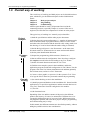
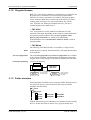
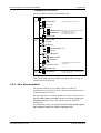
TAC Xenta family v3 Engineering Guidelines LowSupp ALARM LowSuppLimit HYST PVR InitValue 3 DelayOn LowSuppDelay DelayOff 0 Priority 2 Activate 0 Deactivate 0.5 AINL SupplyTemp HeatingREG MV PIDA AI M0-B1 SP HeatSP Mod PVR G InitValue 18 DZ XPI a?1:3 PVR InitValue 25 A XPR 100/A HeatITime PVR InitValue 4 TSg 0 0.5 HeatPband A XPR 60*A 0-004-7639-0 (GB), 1998-08-15 UMin 0 Ti Td a ControlInt 10 UMax 100 StrokeTime 60 Foreword Welcome to the TAC Xenta family v3 Engineering Guidelines. Copyright © 1998 TAC AB. Subject to modification. This document, as well as the product it refers to, is only intended for licensed users of the product and the document. TAC AB owns the copyright of this document and reserves the right to make changes, additions or deletions. TAC AB assumes no responsibility for possible mistakes or errors that might appear in this document. Do not use the product for any other purposes than those indicated in this document. Only licensed users of the product and the document are permitted to use the document or any information therein. Distribution, disclosure, copying, storing or use of the product, the information or the illustrations in the document on the part of non-licensed users, in electronic or mechanical form, as a recording or by other means, including photocopying or information storage and retrieval systems, without the express written permission of TAC AB, will be regarded as a violation of copyright laws and is strictly prohibited. TAC Vista, TAC Menta and TAC Xenta are registered trademarks of TAC AB in Sweden and other countries. All other brand names are trade marks of their respective owners. Revisions Art No 0-004-7639-0 Comment First version. Covers TAC Menta version 3.1, TAC Vista version 3.1 and TAC Xenta version 3.1. Editor CPHA Date 1998-08-15 TAC Xenta family v3 Engineering Guidelines Contents TAC Xenta family v3 Engineering Guidelines Contents 1. Introduction 1-1 1.1. Purpose .................................................................................................................................. 1-1 1.2. Terminology........................................................................................................................... 1-1 1.3. Overall way of working.......................................................................................................... 1-2 1.4. More information................................................................................................................... 1-3 2. Basic project analysis 2-1 2.1. System configuration.............................................................................................................. 2-1 2.1.1. Operator units....................................................................................................................... 2-1 2.1.2. The LonWorks network ........................................................................................................ 2-1 2.2. Point identification/Allocation................................................................................................ 2-2 2.2.1. Standard applications............................................................................................................ 2-2 2.2.2. Execution ............................................................................................................................. 2-3 2.2.3. Standard for TAC Xenta 300 point allocation........................................................................ 2-5 2.3. Acronyms and ID's ................................................................................................................ 2-6 2.3.1. General structure .................................................................................................................. 2-6 2.3.2. Create ID in TAC Menta ....................................................................................................... 2-7 2.3.3. Display the ID ...................................................................................................................... 2-7 2.3.4. Physical ID........................................................................................................................... 2-9 3. Programming 3-1 3.1. Preparations........................................................................................................................... 3-1 3.1.1. Environment and Tools ......................................................................................................... 3-1 3.1.2. Program licenses................................................................................................................... 3-2 3.1.3. Folder structure .................................................................................................................... 3-2 3.2. Application programming...................................................................................................... 3-3 3.2.1. FBD programming................................................................................................................ 3-3 3.2.2. The Macro Block Library ..................................................................................................... 3-5 3.2.3. OP configuration .................................................................................................................. 3-7 3.2.4. User documentation .............................................................................................................. 3-8 3.3. TAC Vista .............................................................................................................................. 3-9 3.3.1. General................................................................................................................................. 3-9 3.3.2. Database generator ............................................................................................................... 3-9 3.3.3. Colour graphics .................................................................................................................... 3-9 3.3.4. Reports and presentations ................................................................................................... 3-10 3.3.5. General working method ..................................................................................................... 3-11 TAC AB, 1998-08-15 0-004-7639-0 (GB) TAC Xenta family v3 Engineering Guidelines Contents 3.3.6. Creating a database for TAC Xenta units ............................................................................ 3-11 3.3.7. System documentation ........................................................................................................ 3-12 3.3.8. Backup............................................................................................................................... 3-12 3.4. Upgrading ............................................................................................................................ 3-13 3.4.1. Upgrading the TAC Xenta units.......................................................................................... 3-13 3.4.2. Upgrading the TAC Vista database..................................................................................... 3-13 4. Commissioning 4-1 4.1. Commissioning with TAC Menta .......................................................................................... 4-1 4.1.1. Initial checking ..................................................................................................................... 4-1 4.1.2. Network configuration.......................................................................................................... 4-2 4.1.3. I/O test ................................................................................................................................. 4-4 4.1.4. Functional test...................................................................................................................... 4-5 Index Reply form This document has 44 pages 0-004-7639-0 (GB) TAC AB, 1998-08-15 TAC Xenta family v3 Engineering Guidelines Introduction 1. Introduction 1.1. Purpose This document describes tools and working methods in the TAC Xenta family (TAC Xenta, TAC Menta and TAC Vista), both hardware and software, that are or could be useful when executing the different tasks in the contracting business. In the document, working methods are proposed and available tools to support them are shown. Also, it will in short describe how to use the tools. All to enable or facilitate the scoop of work within the contracting cycle. 1.2. Terminology The following TAC Xenta family terminology is used in this document: TAC Xenta A standard controller or a freely programmable unit with modular I/O configuration. OP Operator Panel on the TAC Xenta unit. LONWORKS™ The standardised network, used for communication between the TAC Xenta units. TAC Vista A PC based operator unit for monitoring and control of air handling and heating systems. TAC Menta Application programming tool for TAC Xenta. OP configuration tool Programming tool for the TAC Xenta Operator panel, included in TAC Menta. Network Tool for definition of the TAC Xenta units configuration tool network addresses etc., included in TAC Menta. The following abbreviations and acronyms, not explained where they occur, are used throughout the document: TAC AB, 1998-08-15 ASCII American Standard Code for Information Interchange. BMS Building Management System HVAC Heating, Ventilation & Air Conditioning ID Plant specific names/descriptors for points etc. I/O Input/Output 0-004-7639-0 (GB), 1:1 (3) TAC Xenta family v3 Engineering Guidelines Introduction 1.3. Overall way of working The overall way of working in a BMS project can be divided into three parts, which also give the different chapters in this Guideline their names: Chapter 2 Basic project analysis Chapter 3 Programming Chapter 4 Commissioning All three parts should be used by all personnel involved in the contracting business, especially Chapter 2, because if this area is neglected, it will be hard to compensate for it later on in the project. The typical way of working in a "normal" project should be: Project analysis 1) Read the specifications and the other project documents. 2) Do the physical system configuration, i. e. number of operator units, their location and need of program modules, number of TAC Xentas and other units, their location and the network cable wiring (mark it on the drawing, so it can be found when the under ceiling is mounted). 3) Decide the logical layout i.e. the ID structure. At the same time, document each TAC Xenta unit's device name and network address. 4) Do the point identification/allocation. Programming 5) Prepare the programming (folder structure, libraries etc.) 6) Run an off-line network configuration. Note: Do always configure the complete network before down-loading to any TAC Xenta! 7) Define all central functions and units in TAC Vista. 8) Find the most complex system in the installation, and do the application program and the OP configuration in TAC Menta. Test the program, first in the TAC Menta simulation mode and then (primarily the OP menu texts) on-line in a TAC Xenta unit. 9) Create a colour graphic, a report etc. for the system in TAC Vista. 10) Copy the files to the next system and continue the programming. Commissioning 11) Do initial checking on site in the installation. 12) Install program and database in the installation PC. Down-load the application (or a special test application) and the network data base to every TAC Xenta unit. Network configure the I/O modules. 13) Test I/O. 14) Do functional tests. Depending of the size and the contents of the project, the different points in the list may, of course, be omitted, have different size or be executed by different persons or in reverse order. Different activities may happen in parallel, and some times project analysis, programming and commissioning may overlap. In this manual, the different moments are described separately, without taking the parallel activities into consideration. 0-004-7639-0 (GB), 1:2 (3) TAC AB, 1998-08-15 TAC Xenta family v3 Engineering Guidelines Introduction 1.4. More information x Engineering guidelines In addition to this document, there are four important manuals also describing system working methods, but in specific situations: TAC Xenta Network guide Guidelines for how to design a LonWorks network, with or without external equipment. TAC Vista Communication TAC Xenta, direct Guidelines for connection of a LonWorks network to TAC Vista. TAC Vista Installation and upgrading How to installe and uninstall TAC Vista 3.1, and how to upgrade from TAC Vista 1.1, 1.2, 2.0 and 3.0. TAC Xenta Zone System Guidelines Working procedures when designing a zone system based upon TAC Xenta products. x Other manuals Detailed information about the products in the TAC Xenta family can be obtained from the technical descriptions. The TAC Xenta units are described in the following document: TAC Xenta 300 Handbook. TAC Xenta 400 Handbook. TAC Xenta OP Handbook. TAC Menta is described in the following documents: TAC Menta User's manual. TAC Menta Reference manual. TAC Vista is described in the following documents: TAC Vista Basic functions. TAC Vista Database generator. TAC Vista Technical ref. manual. and other manuals. TAC AB, 1998-08-15 0-004-7639-0 (GB), 1:3 (3) Produkt version X, Manualens namn TAC AB, 1997-xx-xx Svarsblankett TAC Xenta family v3 Engineering Guidelines Basic project analysis 2. Basic project analysis The basic project analysis contains some planning activities, which highly affect the engineering hours needed later in the project. 2.1. System configuration System configuration deals with the physical and logical lay-out of the HVAC system: where to place Operator units, TAC Xenta units, and how to connect them. This, of course, must be done in an early stage of the project. 2.1.1. Operator units The networks function (N1 network) in TAC Vista makes it possible to create a system for large or geographically ‘spread-out’ plants. The network is usually established by direct connections between several operator units in a local area network (LAN). From any operator unit the operator has through the network access to resources, processunits and all objects in the distributed database, as if they were stored on the operator unit which he has logged on to. Printers can be connected to each operator unit for printing of graphics, alarms, reports etc. The network functions are described in a separate manual; TAC Vista Networks. How to define nodes in TAC Vista is also described in TAC Vista Basic Functions. 2.1.2. The LonWorks network TAC Xenta units communicate with each other, the Xenta OP and the TAC Vista operator units via the Echelon LONWORKS™ network (N2 network). When designing the network, a lot of things such as network topology, cable lengths, need of extra units for signal amplification/traffic sectioning etc. have to be taken into consideration. How to do this design is described in the TAC Xenta Network guide. Always read the Network guide, also when the network is limited to I/O module and OP communication! Note. The LONWORKS™ network can also be used by devices from other manufacturers forming e.g. light control systems or alarm systems. No matter if these system works in parallel with the HVAC system, or if they are integrated, co-operation is not only important, but necessary to make the systems work at all! TAC AB, 1998-08-15 0-004-7639-0 (GB), 2:1 (10) TAC Xenta family v3 Engineering Guidelines Basic project analysis 2.2. Point identification/Allocation The importance of a good point allocation is often underestimated. There is a very close connection between how well the allocation is done and the efficiency that can be achieved later in the project. With a good allocation, copying techniques can substantially reduce the engineering hours needed for design/manufacturing of electrical panels, which lowers the project cost. Installation and commissioning work is positively affected if the point allocation is done in an efficient way. If standards are followed, and the same point allocation principles are used for HVAC units with similar function, the commissioning and test hours can be reduced. There will also be less risk of making errors and it will be easier to find and correct the faults that are made. The documents you base your identification/allocation on, are normally produced by someone outside your company e.g. a Consult Engineer or a Mechanical contractor. Their main objective when producing these documents is to describe the system as a HVAC function. It is not to describe and allocate I/O signals and devices in accordance with controllers, RPUs and other products from a certain manufacturer. It is your task to translate their HVAC functions into physical system layouts. This work should really start already when the quotation is prepared and submitted. Therefore, even if described in the consultants documents, you should not just accept the allocation of points. Always consider the solution from a project execution point of view, using your intelligence and knowledge to make an "optimal" point allocation. Sometimes there are points related to the security of the installation or of the user and where the allocation is specified as a requirement from some authority e.g. fire authorities or insurance companies etc. In such cases you should of course comply with the specification. Often functions specified as hard-wire interlocked or as a function from a special device, can be carried out in software programming, without affecting the reliability/quality of the project. Normally your costs can be reduced and your profit increased if such a solution can be utilised. Always look for possibilities like that and try to get them accepted by the persons responsible for the specification. Of course you should never alter these things without a discussion and an agreement from them. Any changes must be proposed and documented prior to the signing of the contract, or stated as a clarification in your offer for the project. To summarise: a good point allocation saves money in a project from the start. A bad allocation will cost money and once you have had it, your possibilities to improve later during the project will be limited. 2.2.1. Standard applications The optimum solution is to use complete standard applications for whole units where the I/O allocation are fixed in a TAC Xenta unit, where the colour graphic is standardised and where the function of the whole application is fixed. These standards should be proposed to the 0-004-7639-0 (GB), 2:2 (10) TAC AB, 1998-08-15 TAC Xenta family v3 Engineering Guidelines Basic project analysis customer already in the sales phase and offered instead of the specified functions and solutions, and will affect the price in a positive way. In this way of working in your market place, a library of such standards should be compiled and well documented and not the least, introduced both to your own sales engineers and to your customers. Please note! The whole idea is to sell your standard solutions without any alterations. As soon as you do any changes to "standard" you will have to spend engineering hours and this will increase the price to the same level as a non standard application. Therefore, you shall always keep the list of available standard applications updated and know where to find them. 2.2.2. Execution 1. You begin by identifying the various systems in the specification and their physical location. By "system" is meant an AHU, a heater etc. 2. The next step is to divide these systems into groups. Primarily, look for the systems that already exists as standard applications. Among other systems, each group should contain systems with similar functions and layouts. For example, a project may consist of ten AHUs: - AHU 1 and AHU 2 have two speed fans, a heating coil, a cooling coil, a heat exchanger, a room temperature sensor and a supply air sensor. AHU 1 also has a timer for after hours work. Also AHU 3 has the same function except for the two speed fans and the heat exchanger. These 3 AHUs could be put in the same group, Group 1. - Among the other seven AHUs, you are in the same way able to identify two groups of similar systems. - Finally, one unique AHU, which has no similarities with the other. Function Single speed fans Two speed fans Variable speed Pump, heating Pump, cooling Pump, recovery Damper on/off Frost protection Fire/smoke protection Timer Cooling coil Heating coil Heat exchanger Damper control Room temp sensor Supply air sensor Extract air sensor Pressure sensor Etc. . . Group 1 Group 2 Group 3 AHU AHU AHU AHU AHU AHU AHU AHU AHU AHU 1 2 3 4 5 6 7 8 9 10 X X X X X X X X X X X X X X X X X X X X X X X X X X X X X X X X X X X X X X X X X X X X X X X X X X X X X X X X X X X X X X X X X X X X X X X X X X X X X X X X X X X X X X X X X Diagrams similar to this should be drawn and compiled in the company's estimate of the system. TAC AB, 1998-08-15 0-004-7639-0 (GB), 2:3 (10) TAC Xenta family v3 Engineering Guidelines Basic project analysis Further, there are two heating applications for the different parts of the building, that are similar and could be put in one heating group. There are also two chiller applications that can be regarded as one group. 3. After having identified the five groups, you start the actual point allocation. Start with the system that contains the most complex functions. This system shall then always be used as a master, even when you create a new master for a similar type of system. In this case, select one of the two speed systems in Group 1 as master when copying for the other systems in this group. Allocate the corresponding I/O in this TAC Xenta unit in accordance with the standards in section 2.2.3. Make sure that all points and necessary hardware devices are included in your design. If at a later stage you have to add some points, the layout of the point allocation becomes unstructured and will in a negative way affect the subsequent work with the project. Be careful when you design the master. If you spend some extra time here, you will gain this many times over when working with copies. 4. When the point allocation for the master is done, make one copy for AHU 2 and one for AHU 3. For the single speed unit, leave the points used for switching between low and high speed, the timer and the heat exchanger empty for the time being. Always keep the basic layout of the master intact. This is important for commissioning and maintenance. If you for some reason remove I/O points, or as in this case do not need them, avoid compressing the remaining points. If you do this, in order not to get idle points in the middle, the copying advantages will be reduced. 0-004-7639-0 (GB), 2:4 (10) 5. Complete the other systems in the group and add any signals unique for the units. 6. Continue with the next group using the same methodology. Do not forget to always copy from your origin master! 7. When all the systems have been arranged into TAC Xenta units, allocate the remaining alarms and sensors etc. to the most appropriate TAC Xenta unit. In this way you will use the "idle points" described above and at the same time not destroy your copying advantages. 8. Check that all associated functions are placed in the same TAC Xenta unit as far as possible. TAC AB, 1998-08-15 TAC Xenta family v3 Engineering Guidelines Basic project analysis 2.2.3. Standard for TAC Xenta 300 point allocation • Air handling X1 X2 X3 X4 B1 B2 B3 B4 U1 U2 U3 U4 15-16 17-16 18-19 20-19 9-10 11-10 12-13 14-13 3-4 5-4 6-7 8-7 K1 K2 K3 K4 K5* K6* Y1 Y2 Y3* Y4* 34/35 36/35 37/38 39/38 31/32 33/32 23-24 25-24 26-27 28-27 Smoke detector (NC) Timer Service switch External alarm Supply air temperature Heating coil return water temperature Outdoor temperature Room (Exhaust air) temperature SF Operation indication (Pressure sensor SF) EF Operation indication (Pressure sensor EF) Pump Operation indication Common alarm Thermal wheel, Heat recovery circuit temperature or Heat exchanger pressure guard SF Manoeuvre EF Manoeuvre Heating pump Manoeuvre Common alarm Fans half/full speed (0/1) Heating valve Heat recovery Pressure control SF Pressure control EF Heat recovery pump Manoeuvre on I/O module. • Heating X1 X2 X3 X4 B1 B2 B3 B4 U1 U2 U3 U4 K1 K2 K3 K4 K5* K6* Y1 Y2 Y3* Y4* 15-16 17-16 18-19 20-19 9-10 11-10 12-13 14-13 3-4 5-4 6-7 8-7 34/35 36/35 37/38 39/38 31/32 33/32 23-24 25-24 26-27 28-27 Pump A Operation indication Pump B Operation indication Domestic hot water pump Operation indication External alarm Supply water temperature Radiators Supply water temperature Domestic hot water Outdoor temperature Room temperature Return water temperature District heating Push button, Timer Pulse Cold water/Hot water Pulse District heating Pump A Manoeuvre Pump B Manoeuvre Domestic hot water pump Manoeuvre Heating valve Radiator Heating valve Domestic hot water *) Note. K5/K6 and Y3/Y4 can not be used at the same time. TAC AB, 1998-08-15 0-004-7639-0 (GB), 2:5 (10) TAC Xenta family v3 Engineering Guidelines Basic project analysis 2.3. Acronyms and ID's 2.3.1. General structure The acronym for a point, physical or logical, in a system should be built up in a hierarchical way with different levels, normally four. Level 1 - Level 2 - Level 3 - Level 4 Building/ area number System System number Point Example: 012-AHU-008-TS01_SV Building 12, Air handling unit 8, Temperature sensor 1, Setpoint value 011-RAD-001-CP02 Building 11, Radiator group 1, Circulation pump 2 • Level 1 This level should consist of the Area name or Building number/name or Block. If the point isn't associated with any of the above, it should get the acronym CS or 000. If the installation handles only one building, this level could be omitted. • Level 2 This level should describe the type of connected system, which for example can be: AHU RAD CH DH ZONE DHW Air handling Radiator system Chiller system District heating Zone control Domestic hot water • Level 3 This level is the system again followed by the system number. The system number is a two or three digit number where the first digit could be used to determine the part of the building, the floor or similar. If there isn't any logical use for the first digit it should be 0. The second and third digit is a number between 0 and 9. • Level 4 This is the point level (will also became the TAC Menta/TAC Xenta signal name), describing the point as well as the function of the point. The characters "/ : _" can be used as delimiter between the point and its function. Example: -SF01:RI Run indication for Supply Fan 1. The function level could be: 0-004-7639-0 (GB), 2:6 (10) TAC AB, 1998-08-15 TAC Xenta family v3 Engineering Guidelines MV SV SVC RI FP HL LL RT AL TS % Etc. Basic project analysis Measured value Setpoint value, fixed Setpoint value, calculated Run indication Frost protection High level alarm Low level alarm Run time measurement Alarm Time schedule Position indication Note! These acronyms are suggestions only and must be adapted to local standards and customs. 2.3.2. Create ID in TAC Menta Enter the level 4 ID of the point (e. g. SF01:RI) as a signal name or a constant name in a Function block in TAC Menta, and define it as public. The name is an alphanumeric string with up to 20 characters. The level 1-3 ID of the point is in TAC Menta represented by the block’s Module belonging, which is added to the signal name (syntax: Module\Signal). The Module concept enables you to divide the application program into different systems. Structure the application program so that all public signals that shall be displayed together are placed in the same Module. If all signals in the application belongs to the same system, the Module name can be omitted. Module AHU1 SF01:RI SF01 AHU1 DI AHU1 DO LIGHT TSCH Flood LIGHT DO Module LIGHT TS1 All public signals belonging to the same Module will be handled together (i. e. will be placed in the same logical unit) when being imported to TAC Vista. At the same time, the Module name can be replaced by the level 1-3 ID. Therefore, the Module name can be short, as long as it identifies the system. 2.3.3. Display the ID • Display the ID on central level in TAC Vista To be able to import the application program to TAC Vista (cf. TAC Vista, Communication TAC Xenta, direct), it must have been saved as an .MTA file in TAC Menta. All public signals in the .MTA file will be transferred to TAC Vista by first giving the Create TAC AB, 1998-08-15 0-004-7639-0 (GB), 2:7 (10) TAC Xenta family v3 Engineering Guidelines Basic project analysis TAC Xenta description file command in the Database generator, and then importing the created description file. The three upper ID levels will be created at the same time, just by defining the logical unit corresponding to the Module. Thus, each Module name can be changed to a new logical unit name in TAC Vista. TAC Vista presentation: Database generator - Create TAC Xenta description file TAC Vista - Object selection Current object ID: Current unit: Selected node: Current object type: Physical connection: SF01 012-AHU-AHU01 1 Digital input 012-RPU01 AHU01.SF01 Objects SF01 SF01:RI Units 2 3 1 Select TAC Xenta unit. 2 Select application program (the.MTA file). 3 Enter logical unit (ID level 1-3) for the marked Module. All public signals in the marked Module are created as TA Vista objects in this unit. Process unit: Name -012-RPU01 Type TAC Xenta 300 Application program: Program file C:\PROJECT\012\RPU01.MTA Signals Modules AHU01 SF01 LIGHT SF01:RI LOCK Logical unit 012-AHU-AHU01 Description file C:\PROJECT\012\RPU01.DES Note: - All points in a Module are automatically placed under the same logical unit in TAC Vista. - All object names are presented with capital letters in TAC Vista, no matter how they are defined in TAC Menta. • Display the ID on local level in the TAC Xenta OP The user would appreciate if the ID hierarchy in the OP was exactly the same as in TAC Vista. Unfortunately, this is normally hard to do, depending on that the OP displays the physical view of the network: The TAC Xenta groups, and the TAC Xenta units within each group. If, for example, a TAC Xenta unit holds more than one logical Module, you cannot display a Module without first selecting TAC Xenta unit. Therefore, it is better to consequently let the OP display the physical ID (Cf. Section 2.3.4) down to the level where the OP menu tree of the TAC Xenta unit is displayed: TAC Menta FBD: R02 012_AHU_AHU02 INFORMATION OP. STATUS TEMPERATURES R02 TEMPERATURES TS01_MV: 18.7°C TS01_SP: 19.0°C Outdoor: -10.3°C AINL TS01_MV AHU02 AI M0-B1 TS01_SP AHU02 PVR InitValue 19 The first OP row can be used for presentation of the system(s) (corresponding to ID level 1-3) being present in this specific TAC Xenta unit. Use the Name field in the Program specification of 0-004-7639-0 (GB), 2:8 (10) TAC AB, 1998-08-15 TAC Xenta family v3 Engineering Guidelines Basic project analysis TAC Menta to enter this. The name field allows up to 20 characters, but since the Abbreviation is presented in the same OP row, a maximum of 15 characters can be used. Divide the OP menu tree in different text displays for the different systems (Modules). The actual layout of the displays are created in the OP configuration tool, cf. section 3.2.3. Note that if 15-20 characters are used in a signal name, then you must use two rows in the OP to show the point; one row for the name and one for the value. If you want to show both name and value in the same row the name must be limited to 10-12 characters. 2.3.4. Physical ID • Structure The physical ID is used to identify the physical components of the control system, i. e. the LonWorks network and its TAC Xenta units. Use three levels, where level 1 is the building or part of the building (the LonWorks network), level 2 is the cabinet (TAC Xenta group) and level 3 the TAC Xenta unit. • Physical ID in the TAC Xenta OP The ID structure for the Xenta OP is created when giving the TAC Xenta 300 units their names in the Network configuration tool: Network configuration tool - Group dialog TAC Xenta OP display: Run offline Master Changed Comment LonWorks Network: 012 Cabinet number (ID level 2) Groups Nodes CAB01 CAB02 CAB03 CAB01 CAB02 CAB03 RPU01 RPU02 RPU03 RPU04 MX X X X RPU number (ID level 3) RPU01 RPU02 RPU03 RPU04 TAC Menta - Program specification Abbreviation R02 012_AHU_AHU02 INFORMATION OP. STATUS TEMPERATURES Name: 012_AHU_AHU02 Abbr: Type: Air handling HC-53 Cycle time: Author: M. Smythe Std App. R02 1000 ms Date: 1997/10/21 Used resources: Up to 30 TAC Xenta units can form a TAC Xenta group. A maximum of 30 groups can be defined per network. The group name is shown on the OP top level, where all groups are presented. The OP menu tree of the selected RPU (TAC Xenta unit) is presented as above, with the RPU number on the first row as an Abbreviation, a four letter ID which is presented in all OP menus for the TAC Xenta TAC AB, 1998-08-15 0-004-7639-0 (GB), 2:9 (10) TAC Xenta family v3 Engineering Guidelines Basic project analysis unit. The full ID may have to be shortened when used as abbreviation. The abbreviation is entered in the Abbr. field in the Program specification of TAC Menta. • Physical ID in TAC Vista The physical structure of the network is converted from the Network database into TAC Vista, and will then be displayed in the Status menu. To convert (cf. TAC Vista, Communication TAC Xenta, direct), use the Create description file command in the Network configuration tool, and then import the created description file via the TAC Vista Database generator. TAC Vista Presentation: TAC Vista - Status HOSPITAL PC_12 012 CAB01 RPU01 RPU02 RPU03 RPU04 0-004-7639-0 (GB), 2:10 (10) Network configuration tool - Group dialog LonWorks Network: Groups CAB01 CAB02 CAB03 012 Nodes RPU01 RPU02 RPU03 RPU04 Run offline Master Changed Comment MX X X X TAC AB, 1998-08-15 TAC Xenta family v3 Engineering Guidelines Programming 3. Programming 3.1. Preparations 3.1.1. Environment and Tools The work shall be organised in a PC with Windows environment. If more than one person does programming, the standards used and the structure of the programs are the same. If a network and a server is used, there must be one person responsible so that the organising of the hard disk and back ups etc. are carried out on regular basis. Recommended computer configuration: Computer: Memory: Hard disk: Disk drive: Display: Graphic: Intel Pentium processor, at least 90 MHz > 16 Mbytes at least 50 Mbytes free 3½" 17" or larger VGA Each PC should contain the following programs: - Windows95™ - A good editor, like Microsoft® Word™ - TAC Menta - TAC Vista It is important that tests of the program can be carried out before delivery to the customer or the on-site commissioning. A basic test system could consist of: - A TAC Xenta unit (301/302) - A TAC Xenta OP - A "Simulating box" TAC AB, 1998-08-15 0-004-7639-0 (GB), 3:1 (14) TAC Xenta family v3 Engineering Guidelines Programming 3.1.2. Program licenses Both TAC Vista and TAC Menta uses a hardware key connected to the PC printer port to lock/unlock (via password) program modules. Therefore, it is always important to, in advance, check the program license of the PC (Both at the customer and at the office) you will be working with, or always to use your own hardware key. If both TAC Vista and TAC Menta are installed on the PC, just one (a common) hardware key shall be used. • TAC Vista TAC Vista consists of a basic module with functions for daily operation of the plant. Depending on the customer's requirements there are optional program modules such as Colours graphics editor, Reports and presentations etc. which can be individually locked/unlocked. Note: Communication with TAC Xenta is such an optional module. • TAC Menta The following TAC Menta licenses are available (cf. figure below): Demo No hardware key required. On-line functions, code generation and Save to file disabled. Service/configuration The tools OP configuration and Network configuration are available, as also On-line functions, simulation and code generation in the main program. Source code changes are blocked by disabling the Edit mode. Normal/programming Access to all functions. Hardware key TAC Xenta Base unit TAC Menta Service/ configuration • On-line functions • Code generation Normal/ programming • On-line functions • Code generation • Edit mode 3.1.3. Folder structure Each programmer should have his own project folder. When he starts a new project he opens a new sub-directory and copies in suitable templates from the library. project bldg12 012.DES RPU05.DES RPU06.DES 012.OGC RPU05.MTA RPU06.MTA 012.NDB ... With the information given in the hand-over meeting, he starts creating the TAC Xenta unit which is 'master' for a group of similar units. 0-004-7639-0 (GB), 3:2 (14) TAC AB, 1998-08-15 TAC Xenta family v3 Engineering Guidelines Programming When the 'master' TAC Xenta unit is completed and tested, make copies for the other TAC Xenta unit's in the group, and complete the programming of each TAC Xenta unit. Then start with the next group of systems using the same method. 3.2. Application programming The application programming of the single TAC Xenta unit can be divided into the following phases; Function phase, Design phase and Test phase: Function phase Design phase Test phase FBD programming Functional specification OP configuration System tests Delivery to plant, commissioning User documentation In the Function phase the Functional specification is read and completed with your own analysis in accordance with the description in chapter 2. At this stage you will know how much you can copy the system from another TAC Xenta unit. During the Design phase, the Application program (FBD programming in TAC Menta), OP display texts (OP configuration tool in TAC Menta) and the User documentation is created more or less in parallel. The Test phase contains two parts: - Off-line functional tests of the program modules are integrated in the design phase. - A final system test where the complete application including the OP menu tree is down-loaded to a TAC Xenta unit and tested. Please note that the application can and shall be completely tested in the office before delivery to plant and commissioning. 3.2.1. FBD programming In a FBD, the function blocks process input signals to generate a single output signal. The output signal is transported to other blocks following the route defined by the connections, which represent the data flow, from left to right, during the program execution. Data flow DI Connections DO A complete TAC Menta program description is found in the TAC Menta User's Manual, and all the function blocks are described in detail in the TAC Menta Reference Manual. TAC AB, 1998-08-15 0-004-7639-0 (GB), 3:3 (14) TAC Xenta family v3 Engineering Guidelines Programming • Structuring the FBD The design phase is started with the overall structuring i.e. to find the main function groups and to find out how to graphically place the groups in relation to other groups. The first step is to find suitable function groups. This grouping can be made in a number of ways. The general idea is to make the FBD easy to understand and alter, therefore function blocks that perform a function together, also should be placed together. This could be done in levels, so that for example all blocks used for sequence control are placed together, but inside this "Sequence control box" we find groups of blocks for "Heating", "Heat exchanger", "Cooling" etc. A part of this step is to find the functions which already exist in your own library or in the Macro Block Library in form of macro blocks, refer to section 3.2.2. The second step is to graphically place the groups. Create a left-toright logical sequence in the FBD, meaning that if there is a connection between two groups, place the "output group" to the left of the "input group". The logical order from left-to-right should be: START CONDITION - STOP CONDITION - GENERAL CONTROL - PID CONTROL SEQUENCES - ALARM HANDLING: Program header STOP CONDITION START CONDITION GENERAL CONTROL PID CONTROL SEQUENCES ALARM HANDLING • Creating the FBD Start the programming by defining the current configuration (Base unit type 301, 302 or 401; number and types of I/O modules, if present) in the Device configuration table. Thereafter it is time to place blocks and groups in accordance with the described structure. Use the following rules of thumb: • Place a bus with common left-to-right directed connections in top of the diagram. Try to avoid connections going in the opposite direction, but when necessary, put these connections in a separate bus at the bottom of the page. Mark the direction of these signals. 1.7-9 1.7-6 1.7-10 1.7-1 1.7-12 1.7-11 1.7-7 1.7-8 1.7-5 1.6-9 1.6-6 1.6-10 1.6-1 1.6-12 1.6-11 1.6-7 1.6-8 1.6-5 Fan control Cooling/heating sequence <<< <<< 1.7-4 1.6-4 1.7-3 1.6-3 1.7-2 1.6-2 • Use plenty of space between the groups, so that there will possibilities to draw extra connections and additional functions. Also adjust the FBD to the page break lines, so that the printout will be easy to read. • Add new pages to the right when needed, but try to use only one page in vertical direction. 0-004-7639-0 (GB), 3:4 (14) TAC AB, 1998-08-15 TAC Xenta family v3 Engineering Guidelines Programming • Try to structure every page so that the physical input blocks are placed in a row to the left, and the physical output blocks are placed in a row to the right. • Re-use tested macro blocks from the Macro Block Library or from your own library as much as possible. • Enter a framed comment containing last edition date of the FBD in the upper left corner. Also History notes describing the revision can be included. Update this information whenever you make a program revision: Start/stop Night heating Air handling Appl:S3412SS-130 Version no.: 1.0 Last edited: 96-10-24 Author: Jan Wallsby Sensor err One speed fans Two stage sequence control; cooling/heating Outdoor compensated supply air control Night cooling Night heating REVISION Date Version Alteration 960930 1.00 First version 961024 1.01 System alarm added • Test and debugging Use Simulation mode. Don't forget that you can use automatic generation of different wave forms on the inputs. 3.2.2. The Macro Block Library You shall always keep a list of updated standard applications and macro blocks in a locally available library, and know where to find them. • The TAC Menta Macro Block Library TAC supports a central library for application programs designed with TAC Menta. In the library, you can find examples of control and supervisory functions, process models and macro blocks for different other functions. All these applications (or parts of applications) have been tested and approved according to TAC's quality system, although not necessarily designed by TAC. The purpose of the official library is to: x x x provide examples of how to implement different functions. make it possible to design a new application easily and quickly. make it easy to test an application with simulated process response. Each folder in the Macro Block Library has a README.DOC file which explains the functionality of the different programs. The programs in the directories have two parts, a graphical FBD and a text description in an associated text file. TAC AB, 1998-08-15 0-004-7639-0 (GB), 3:5 (14) TAC Xenta family v3 Engineering Guidelines Programming • Macro block A macro block should follow these rules: x The whole block should have a dotted line around it. x Block name in upper left corner; bold text, size 12 and underlined. x Place last edit date and programmer signature near the block name. x Place Input signals on the left side, with explanations and units. x Place Output signals on the right side, with explanations and units. x A short description of the function, wherever suitable. Example: name: hotwater.aut Domestic hot water control File Last edition: 96-10-01 Author: Mikael Krantz For history notes, please see associated text file. HotWaterControl Domestic hot water temperature, °C ActualHotWaterSP (R l) HotWaterSV 1 PVR InitValue 50 1 MV PIDA SP ControlInt 1 Mod 0 UMin G Control signal, % (R l) 0 Ti HotWaterPBand HWGain PVR HotWaterSetback PVR XPR 50 0 0 100 DZ InitValue StrokeTime HWTravelTime TSg 30 100/A UMax Td PVR InitValue InitValue HWCDzone HotWaterTime TSCH A HotWaterITime A XPB PVR InitValue A<0 The domestic hot water controller has a load depending deadzone change over, to take care of low flow at HW C. There is also a time control to set a setpoint offset during night periods. 1 5 0 HYST 0.5 HWCFlow PVR Activate -1 Deactivate 1 InitValue 10 HW C flow The dead zone changeover takes place when the output signal goes below the "HWCFlow" set limit with a hysteresis of +- 1%. • Text file The text file may be written with any kind of editor, but must be an ASCII-file with the extension .TXT, WRI or .DOC. The text file should contain a full functional description of the macro block, a list of inputs and outputs (including their types and units), and also a list of all public variables with their initial values and units. It should also have a history list with notes of all changes that are made in the program with date and signature of the programmer. Note that text files generally are very useful: 0-004-7639-0 (GB), 3:6 (14) • The function descriptions in the macro block text files can be copied to a text file with the same name as the application program, which then can be invoked from TAC Menta. • Alternatively can the associated text file in TAC Menta be copied from the origin functional specification. • The associated text file can be used in TAC Vista as a notepad file, which can be chained to a colour graphic to present an information text for the displayed system. • A notepad file can in TAC Vista be chained to an event enrolment object, and thus give the operator a list what to do when an alarm is tripped. TAC AB, 1998-08-15 TAC Xenta family v3 Engineering Guidelines Programming 3.2.3. OP configuration The TAC Xenta OP is used to give the operator access to plant status, alarms and parameters. The information is presented as a number of 4*20 character displays. The displays are structured as a menu tree. This chapter contains some hints on how to structure the menu tree. • Automatic generation of the menu tree The menu tree will automatically be generated at every generate/download command in TAC Menta, if Preferences Automatic generation of menu tree is selected in simulation mode. The generated menu tree will have a fix structure with all public signals and constants divided into separate displays for digital signals, analog signals and time schedules. Also, different modules will be presented separately. This is the quickest way to create a menu tree, and should be used if there is no specific demand for a menu tree structure. The disadvantage is that you in this way may get very long and unstructured signal lists. • Structuring the menu tree manually You can manually configure the OP menu tree and the text displays in two different ways, both described in the TAC Menta User's Manual: 1) Graphically in the OP configuration tool, or 2) In a text file (the OP description file), which is imported to the OP configuration tool. In both cases, the menu tree structuring mainly consists of two parts: • The Logical structuring, meaning to group items which are logically connected together e.g. all fan parameters. • The Operator dependent structuring, meaning to divide the items into groups with different interest for different operators. The first rule of thumb is to place items of interest for the daily operator at the top of the menu tree. The daily operator, having a low access level, should mainly be able to read the plant status, read and acknowledge alarms and alter a few values, typically the setpoints. Settings which are seldom altered, and then by an authorised operator with medium or high access level, are placed further down in the menu tree. TAC AB, 1998-08-15 0-004-7639-0 (GB), 3:7 (14) TAC Xenta family v3 Engineering Guidelines Programming • Standard for OP menus The basic menu tree structure should be like this: NAME Low access INFORMATION - Application type and version OP STATUS VALUES TEMPERATURES- Measured values and Setpoints (RO) one display per value DEGREE DAYS - Last month's degree days one display per value ACCESS CODE Medium access (level 1) DATE & TIME ALARMS SETPOINTS TEMPERATURES- (R/W) CURVES TIME SCHEDULES WEEK CHARTS HOLIDAYS START - Auto/Manual switch and Restart of the AHU DAYLIGHT SAVING CHANGE CODE High access (level 2) PARAMETERS - Control parameters, system parameters such as delays etc. Note that there is no need for a specific manual control menu. The I/O points can be manually forced in the status menu, if the user logs in with the high level password. 3.2.4. User documentation The printout function of TAC Menta contains a number of possibilities, but you don't have to use all since some information are included in more than one list. The most important TAC Menta printouts in a TAC Vista project are I/O list, public signals and FBD, together with colour graphics and description files from TAC Vista, and of course the functional specification. In a stand alone project, you should document I/O-list, public signals, time schedules, alarm texts, FBD and OP menu tree. 0-004-7639-0 (GB), 3:8 (14) TAC AB, 1998-08-15 TAC Xenta family v3 Engineering Guidelines Programming 3.3. TAC Vista 3.3.1. General A TAC Vista system is built up of objects, defined in a database. The database must exist before you can convert control programs, or use address symbols and values in colour graphics etc. TAC Vista may use absolute or relative addressing. Relative addressing means that you - for example in a colour graphic (BLDGAFLOOR4-PICT) - refer to the last level of the object IDs. Absolute address: BLDGA-FLOOR4-T1, relative address: T1. By means of relative addressing the colour graphics can easily be moved to another location in the logical tree structure where there also is a point named T1. 3.3.2. Database generator To program the objects and their attributes in an efficient way you use the Database generator, cf. the TAC Vista Database generator manual. In the Database generator you can perform editing and syntax check of description files. You can convert RPU documents and TAC Xenta units and you can export and update data to the description file. You can also import data to the database. There are template files with predefined texts and attributes for different types of process units. Try to create a number of description files, each for a specific process unit or part of the project. The data in the different description files can be imported to the database at the same time via a batch file. 3.3.3. Colour graphics The colour graphic editor offers the option to document which points the graphic contains in a list that is easy to survey. In the editor you may also simulate the dynamic functions in the colour graphic. When creating colour graphics for the plant, it is a good idea to create a tree structure with an overview graphic "at the top", from which you can reach lower levels of the plant, and to which you can return. The overview graphic may be in the form of an imported photographic image or a plant drawing, over which transparent link areas can be placed. These link areas fetch the colour graphics for the relevant part of the plant. For further details, see the section on link areas below. Plan the tree structure for graphics in a way that makes it easy for the user, and facilitates adding new graphics when the plant is changed. Be consistent in the use of colours and line types. Create documentation on the selection of colours and line types in the system by keeping a record. See the standard on the following page. TAC AB, 1998-08-15 0-004-7639-0 (GB), 3:9 (14) TAC Xenta family v3 Engineering Guidelines Programming Example: Record showing colours and line types for the plant HOSPITAL. HOSPITAL - colours and line types in colour graphics Background ..............Dark grey VARIOUS MEDIA Line size thickness 2: Water Cold..........Dark blue Water, supply ..............Red Water, return ..............Dark blue Water ..............Red Water Cooling media.Light blue Waste water ..............Green Consumption, hot water ..............Red Compressed air ..............Light blue Oil, other gases ..............Yellow Line size thickness 3: Air vent system, supply air.............Dark blue Air vent system, exhaust air............Red FIXED SYMBOLS All static symbols ..............Black frame ..............Dark grey backgr. TEXT Descriptive text, measuring units and handling unit names ..............Black MODES OF OPERATION In operation ..............Green Out of operation, also RPU offline......Red Forced ON ..............Blue Forced OFF ..............Purple Alarms are shown as the pre-set colours of the alarm overview. ANALOG VALUES Calculated value ..............Yellow, gray bkgr. Setpoint ..............Yellow, blk bkgr. Measured value ..............Light green Moist in % ..............Green Damper and valve positions..............Dark red Values should be shown with three digits accuracy, e. g. temperatures with one decimal and pressure in Pa with no decimals. Damper and valve positions will be shown as percentages between 0 and 100% reflecting the opening degree. 3.3.4. Reports and presentations To create reports, presentations and energy signature, there are three program modules built around the Microsoft Excel program. 0-004-7639-0 (GB), 3:10 (14) TAC AB, 1998-08-15 TAC Xenta family v3 Engineering Guidelines Programming 3.3.5. General working method The following general working method shall normally be used when creating a TAC Vista system, no matter if it is connected to TAC ZONE II units or TAC Xenta units: 1 - Install the TAC Vista software on the PC. 2 - Do the point identification/allocation in accordance with chapter 2. 3 - Create a system description file (Use either SYSTEM.DEM or LONWORKS.DEM as a template) describing all central functions and units such as communication ports, alarm processing objects, alarm receivers, trend logging objects etc. and import it to the database by means of the Database generator. 4 - Create a description file for each RPU in the system. Edit the description file and import it to the database by means of the Database generator. 5 - Draw, copy and/or edit Colour graphics, Reports and Note files. Save them as .OGC, .XLS and .TXT files respectively. 6 - Add Colour graphic and Report objects to the RPU description files and import again. Remember to put the graphic in the same logical unit as the points it is displaying. 7 - Make a function check, cf. chapter 4. 8 - Update all description files. 3.3.6. Creating a database for TAC Xenta units Use the working method below when creating a TAC Vista database for TAC Xenta units, cf. TAC Vista Communication TAC Xenta, direct. From version 3.1, it is possible to download the application program to TAC Xenta either via a direct connection to TAC Menta, or via TAC Vista and the LonWorks network. Below, download via the network is shown, but the application might as well be downloaded by using TAC Menta when directly connected under stage 2. 1 - Create the application program in TAC Menta (cf. section 3.2), and save all files as an .MTA file in the folder for the TAC Xenta unit in question. Repeat these actions for all TAC Xenta units. 2 - Create the LonWorks network, the Groups and the Nodes (the TAC Xenta units) in the Network configuration tool. Configure all the TAC Xenta units including their I/O modules. Save the network database as an .NDB file. Thereafter, download the network configuration to the TAC Xenta units, one by one, via the serial port. 3 - Create a system description file (use LONWORKS.DEM) and import it to TAC Vista. Note especially the communication port for the LTA unit and its address, e. g. PCCLON1. TAC AB, 1998-08-15 0-004-7639-0 (GB), 3:11 (14) TAC Xenta family v3 Engineering Guidelines Programming 4 - Create a Network configuration description file (reads the .NDB file) and import it to TAC Vista. The file should have the same name as the network, e. g. BLDG012.DES. 5 - Set TAC Vista in on-line mode. Open the LonWorks network object and check the domain table and the address table. Enter the TAC Vista Status menu and check that the TAC Xenta units are on-line. 6 - Convert the application program for a TAC Xenta to a description file via the Create TAC Xenta description file command in the Database generator's Tools menu. Enter the requested logical unit for each module in the application program. Place the description file in the same folder as the .MTA file. Edit the description file, if needed. Alarm object references etc. may have to be added. Note that these alterations in the description file are deleted if you convert the application program a second time. Therefore, always note your alterations! Import the description file. Repeat point 6 for every TAC Xenta unit in the system. The system definition phase can be speeded up, if the description files are run via a batch file defined in the Database generator. Place the batch file and the description files in the same folder. 7 - Download the application program by selecting Status in the menu Show and mark the unit(s) to be downloaded. Then select Download application and parameters in the pop-up menu (right mouse button). Check that you have contact with the TAC Xenta points. 3.3.7. System documentation In TAC Vista it is easy and fast to document the system by means of predefined lists: - System configuration - Process units - Objects - Inputs/Outputs - Check list - Forced variables 3.3.8. Backup Note that a new backup function has been implemented in TAC Vista v3.1, to backup the TAC Vista database. Both a complete and an incremental backup is included. It is simple to perform backup of all operator units in a TAC Vista network and storing the backups on a common network server. 0-004-7639-0 (GB), 3:12 (14) TAC AB, 1998-08-15 TAC Xenta family v3 Engineering Guidelines Programming 3.4. Upgrading An important part of our work is to upgrade existing plants with new functions, without having to rewrite the old applications and data. 3.4.1. Upgrading the TAC Xenta units An upgrade of the TAC Xenta system software is done by using the Download Wizard, which is a part of TAC Menta. When upgrading, TAC Menta must be directly connected to the TAC Xenta unit in question. At the same time as the system software is upgraded, the application program and the network configuration can either be reloaded (depending on version, you must in some cases have access to the original source code files) or be replaced by new data. The Download Wizard and the TAC Xenta units upgrade is further described in chapter 9 in the TAC Menta User’s manual. 3.4.2. Upgrading the TAC Vista database How to upgrade TAC Vista and the database is described in TAC Vista Installation and upgrading. A new function in TAC Vista 3.1 is network download of the application program, cf. chapter 9 in TAC Vista Communication TAC Xenta, direct. This new possibility implies two things to especially consider when upgrading to version 3.1: 1 - Updated plant data Whenever the application program in the TAC Xenta unit is redesigned, you shall check that the plant data is correct. Normally, updated values are stored in the TAC Vista database. However, should the user have altered settings via the TAC Xenta OP, all altered values will not automatically be uploaded, but an Upload - only parameters is required. Then, to update the MTA file with the current data from the TAC Vista database the Export data from database in the database generator is used. How to alter or change the TAC Xenta application program is described in detail in section 8.5 in TAC Vista Communication TAC Xenta, direct. 2- Application for download from TAC Vista In the previous TAC Vista versions, the TAC Vista database only had to contain information about the TAC Xenta network configuration and the variables (I/O points, set points, settings etc.) being present in a unit. Today, the database must also hold a copy of the TAC Xenta unit’s application. This application must in most cases be regenerated in TAC Menta and then be imported to TAC Vista. TAC AB, 1998-08-15 0-004-7639-0 (GB), 3:13 (14) TAC Xenta family v3 Engineering Guidelines Programming The contents of the data being transferred between TAC Menta and the different TAC Vista versions are explained in short below: TAC Menta COD TAC Vista Description file The parameters of the application were imported via a separate COD file; the network configuration via a description file. v2.0 Values Application COD BIN CHR BPR LonWorks network Serial port MTA COD ... TAC Vista TAC Menta NWC v3.0 TAC Xenta The COD file was included in an MTA file, which also could contain other application files, although not used by TAC Vista. The network configuration was imported via a separate NWC file. Values Application COD BIN CHR BPR TAC Menta MTA COD BIN CHR ... TAC Xenta NDB NWC IOD TAC Vista v3.1 In addition to the COD file, also BIN and CHR files must be included in the MTA file to enable network download. The BPR file is generated from NWC and IOD files (for I/O modules),included in the NDB file. Values Application COD BIN CHR BPR 0-004-7639-0 (GB), 3:14 (14) Application COD BIN CHR BPR TAC Xenta TAC AB, 1998-08-15 TAC Xenta family v3 Engineering Guidelines Commissioning 4. Commissioning How to commission the installation depends on its size and complexity. A single standard TAC Xenta unit with or without I/O modules can be commissioned without any other tool than the OP, cf. TAC Xenta Handbook, on the condition that the Service Menu is present in the OP. When the TAC system is integrated with systems from other vendors, a co-operation between TAC Menta and an external tool is needed. Especially the network and all functions working via the network are affected, cf. TAC Xenta Network Guide. Always first consult the Guide when dealing with network tasks such as cable types and lengths, traffic sectioning and the need of additional equipment (repeaters, routers, gateways etc.). In all other situations, the only tool needed is TAC Menta. 4.1. Commissioning with TAC Menta Commissioning in the following steps: 1 - Initial checking (to avoid high voltage in to the electronics) 2 - Network configuration (Connecting the TAC Xenta units) 3 - I/O test 4 - Functional test (of the application program) 4.1.1. Initial checking For each TAC Xenta unit and I/O module, the following must be checked after the wires have been connected, but before the electronics part is mounted on the terminal part. TAC AB, 1998-08-15 • Turn on the power. • Check that the supply voltage, 24 V AC or DC is connected to the proper terminals G and G0. • Check that the voltage levels of the input and output terminals are reasonable. • Check the voltage, both AC and DC, between G0 and all other terminals. Repeat the procedure with G as the reference terminal. 0-004-7639-0 (GB), 4:1 (5) TAC Xenta family v3 Engineering Guidelines Commissioning 4.1.2. Network configuration Before it can start to communicate, each TAC Xenta unit must be assigned a network address, i. e. a subnet/node address and a device name. To do this a PC with TAC Menta is needed. It is a good idea to, if possible, mount and configure the TAC Xenta units one by one, instead of mounting all at the same time and then configuring them. For each TAC Xenta unit do the following to set the network addresses: • Note! Turn off the power and mount the electronics part on the terminal part. It is important that the electronics part has the same input/output configuration as the terminal part. Also check that correct type of base unit is being used: - TAC Xenta 300 N communicates with other TAC Xenta base units. - TAC Xenta 300 NP also communicates with TAC Vista. • Turn on the power again. • Connect the PC to the TAC Xenta unit: TAC Menta: - Application download - Device configuration - Online simulation TAC Xenta Base unit • Start the Network Configuration tool from the TAC Menta program group on the PC. Open the network database, cf. TAC Menta User's manual, and select group and node (the name of the connected TAC Xenta unit). Edit node -RPU03 File Edit Database: Base unit: Device name: RPU03 RPU03 Subnet: 10 2 Node: 30 25 Neuron ID: 210987654321 210987654321 Version: 3.00 3.00 Unit type: 302 302 Master Comment: Building A, North I/O modules: No CF Sub Node NeuronID 1 0 10 33 123456789012 2 0 10 34 826456389219 Status: 4:2 (5), 0-004-7639-0 (GB) OK Type Version Status 411 1.00-02 On-line 411 1.00-02 On-line Close TAC AB, 1998-08-15 TAC Xenta family v3 Engineering Guidelines • Commissioning Check that the configuration data to be downloaded are correct. It is very important that all units are defined in the network database before you start down-loading the data to any unit. Whenever you add a unit or alter its configuration, you must down-load the configuration data to all units in the group again! If you add a TAC Xenta group, you must down-load the configuration data to all units in the network! Configure the TAC Xenta unit and its I/O modules. To identify an online I/O module, its service pin can be pressed. Note that the configuration data stored in the TAC Xenta unit will not be affected by a later download of the application program. The following network addressing is recommended: Address the TAC Xenta units as Node no 10, 20, 30 etc. starting on Subnet no 10 (Subnet 1-9 should be reserved for future use of routers and external equipment, cf. TAC Xenta Network Guide). Then, use Subnet no 11, 12 etc. The Subnet no 10 Node no 100 TAC Xenta unit will thus be followed by the TAC Xenta units addressed as Subnet no 11 Node no 10 and Subnet no 11 Node no 20. Note, however, that you are not allowed to use the same subnet on both sides of a router, cf. TAC Xenta Network Guide. TAC Xenta Device name: RPU01 Network address: - Subnet no. 10 - Node no. 10 TAC Xenta Device name: RPU02 Network address: - Subnet no. 10 - Node no. 20 An I/O module always belongs to a specific TAC Xenta unit. Therefore, if existing, address the I/O modules belonging to the Subnet no 10 Node no 10 TAC Xenta unit as Subnet no 10 Node no 13 and Subnet no 10 Node no 14, and the I/O modules belonging to the Subnet no 10 Node no 20 TAC Xenta unit as Subnet no 10 Node no 23 and Subnet no 10 Node no 24. Note that two node numbers after the TAC Xenta unit number must not be used, since they are reserved for dynamic addressing of Operator panels. RPU03 TAC Xenta Module no.: 1 Module no.: 2 Module type: 421 Module type: 411 I/O I/O Network address: Network address: Network address: - Subnet no. 10 - Subnet no. 10 - Subnet no. 10 - Node no. 30 - Node no. 33 - Node no. 34 TAC AB, 1998-08-15 0-004-7639-0 (GB), 4:3 (5) TAC Xenta family v3 Engineering Guidelines Commissioning 4.1.3. I/O test The best way to test the external equipment connected to the TAC Xenta unit's inputs and outputs, is to down-load the application program, and then use the TAC Menta on-line functions to test the I/O points one by one. Thanks to the on-line trend-log one person can locally open/close the inputs one by one, and then afterwards consult the trend-log to see that they were activated in the correct order. Alternatively, you can by means of a special test application, where each input is connected to an alarm block, open/close the inputs one by one, and then consult the OP alarm list to see that the alarms were tripped in the correct order. Note! It is important to first check that no danger may occur when setting the outputs. • Connect the PC to the TAC Xenta unit. • Start TAC Menta and open the application program. • Down-load the program, using the On-line button in TAC Menta's Simulation mode. • Check that the LED on the front starts to blink, indicating that the internal program is running. • Check the I/O points one by one. The current status/value of the I/O point is dynamically updated in the corresponding function block. Each I/O value can be forced by means of the Override button in the I/O configuration table. If a faulty I/O binding (Incorrect terminal reference, input/output range etc.) should occur, this can be corrected via the Bind button in the same table. Note, however, that the application program must be down-loaded again after altering the binding information. Note that the same application program can be down-loaded to a number of TAC Xenta units. In this case, use the Program specification to set the correct TAC Xenta unit name before downloading each TAC Xenta unit: 4:4 (5), 0-004-7639-0 (GB) TAC AB, 1998-08-15 TAC Xenta family v3 Engineering Guidelines Commissioning Program specification Name: 012_AHU_003 Type: Air handling HC-53 Author: M. Smythe Abbr: Std App. Used resources: Blocks: DIs 3 53 Public signal table: Identifier EF EFAlarmDelay EF_Op FanDelay HeatITime HeatPband HeatSP LowSuppLimit MV OK R03 1000 Cycle time: Date: 1997/10/21 I/O signals: AIs DOs 2 4 Type Access DIG PAI DIG PAR ANA ANA ANA ANA ANA RO RW RO RW RW RW RW RW RW ms AOs 1 Units seconds seconds minutes °C °C °C Cancel The entered Name and Abbreviation (max. 4 characters) will automatically be generated and down-loaded to the TAC Xenta unit's OP menu system, after pressing the On-line button. 4.1.4. Functional test The application program should always be offline tested in the TAC Menta Simulation mode. At commissioning the following is tested: TAC AB, 1998-08-15 • Connect the TAC Xenta OP. Log in to the TAC Xenta units one by one. • Select the Temp & Status menu (or corresponding) to check that all inputs have got reasonable values. • Check all settings against the specification. Document alterations, when applicable. • Tune the PID control loop parameters. Use the TAC Menta on-line simulation mode trend-log. 0-004-7639-0 (GB), 4:5 (5) Produkt version X, Manualens namn TAC AB, 1997-xx-xx Svarsblankett TAC Xenta family v3 Engineering Guidelines Index Index A M Abbreviation 2:8, 4:4 Acronym 2:6 Air handling 2:5, 3:6, 3:10 Application programming 3:3 Macro block 3:4, 3:6 Manuals 1:3 Move a point 2:10 B N Backup 3:13 Basic project analysis 2:1 Bus 3:4 Network 2:1, 2:7, 4:1 Network address 4:3 Network configuration tool 1:1, 2:7, 3:12, 4:2 Node 2:7, 4:2 C O Colour graphics 2:10, 3:10 Commissioning 4:1 Connection 3:3 Object selection dialog 2:9 OP 1:1, 2:7, 3:8 OP configuration tool 1:1, 2:8, 3:8 Operator unit 2:1 D Database generator 2:9, 3:10 Debugging 3:5 Description file 2:9 Device configuration table 3:4 Device name 2:8, 4:2, 4:4 E Environment 3:1 F FBD programming 3:3 Folder structure 3:2, 3:6 Function block 3:3 P Point allocation 2:2, 2:5 Program header 3:5 Program license 3:2 Program specification table 2:7, 4:4 Public signal 2:8 R Relative addressing 2:10, 3:10 Reports 3:11 S Hardware key 3:2 Heating 2:5, 3:6, 3:10 Standard 2:5, 2:6, 3:9, 3:10 Standard application 2:2 Status menu 2:9 Subnet 4:2 System configuration 2:1 System documentation 3:13 I T ID 2:6 I/O module 4:3 I/O test 4:3 TAC Menta 1:1, 3:2, 3:3, 4:1 TAC Vista 1:1, 2:1, 2:9, 3:2, 3:10, 3:13 TAC Xenta 1:1, 3:12, 3:13, 4:2 TAC Xenta group 2:7 Terminology 1:1 Test 3:5, 4:1, 4:4 Text file 3:7 Tools 3:1 H L Library 3:5 LONWORKS 1:1, 2:1, 4:3 TAC AB, 1998-08-15 0-004-7639-0 (GB), Ind:1 (2) TAC Xenta family v3 Engineering Guidelines Index U Upgrading 3:13 User documentation 3:9 W Working method 1:2, 3:3, 3:12, 4:1 Ind:2 (2), 0-004-7639-0 (GB) TAC AB, 1998-08-15 TAC Xenta family v3 Engineering Guidelines Reply form You can help make this manual even better! We need your help to produce user-friendly documentation and would appreciate it of you would make a note of any errors in this manual or of any suggested improvements. Send to: Or e-mail to: TAC AB [email protected] Helpdesk Jägershillgatan 18 SE-213 75 MALMÖ SWEDEN ----------------------------------------------------------------------------------------------------------------------------I have found the following errors and/or unclear descriptions in the ”TAC Xenta family v3 Engineering Guidelines” (Art.no. 0-004-7639-0 (GB)): On page:............................................................................................................................................... ............................................................................................................................................................ ............................................................................................................................................................ On page:............................................................................................................................................... ............................................................................................................................................................ ............................................................................................................................................................ On page:............................................................................................................................................... ............................................................................................................................................................ ............................................................................................................................................................ I suggest the following improvements: On page:............................................................................................................................................... ............................................................................................................................................................ ............................................................................................................................................................ On page:............................................................................................................................................... ............................................................................................................................................................ ............................................................................................................................................................ My name is: TAC AB, 1998-08-15 Company: 0-004-7639-0 (GB) TAC Xenta family v3 Engineering Guidelines 0-004-7639-0 (GB) Reply form TAC AB, 1998-08-15 Produkt version X, Manualens namn TAC AB, 1997-xx-xx Svarsblankett Produkt version X, Manualens namn Svarsblankett TAC AB, Jägershillgatan 18, SE-213 75 MALMÖ, SWEDEN, +46 40 38 68 50 (switchboard) TAC AB, 1997-xx-xx