1
User Manual
Expert Net Control 2301
© 2014 Gude Analog- und Digitalsysteme GmbH
Manual Ver. 1.4.0
valid from Firmware Ver. 1.0.0
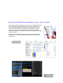
Have your Gude devices always in view - and in control.
With the free Gude Control App you can retrieve all relevant information
from your GUDE products regardless of their current whereabouts.
Check with your smartphone the important operating figures of your
server and rack environment like sensor values (max/min), energy
consumption as well as state of inputs and outputs with watchdog
functions. In particular, connected consumers can be switched remotely
with Gude Control.
"Gude Control" is available for the Expert Power Control 8220/8225
series and can be free downloaded from the Google Play Store and
iTunes Store.
Expert Net Control 2301
Table of contents
3
Table of contents
Chapter 1 Device Description
5
1.1
Security Advice
5
1.2
Content of Delivery
5
1.3
Description
5
1.4
Installation
6
1.5
Connection Example
7
1.6
Status LED
7
1.7
Digital Inputs
8
1.8
Bootloader Mode
9
1.9
Firmware-Update
10
1.10
Technical Specifications
11
1.11
Sensor
11
Chapter 2 Operating
12
2.1
Operating the device directly
12
2.2
Operating by Webinterface
13
2.3
Using the Serial Interface
14
Chapter 3 Configuration
15
3.1
Configuration by Software
15
3.2
Configuration via Webinterface
17
3.2.1
Configuration - Output Ports
18
3.2.2
Configuration - Watchdog
19
3.2.3
Configuration - Input Ports
21
3.2.4
Configuration - IP Address
21
3.2.5
Configuration - IP ACL
22
3.2.6
Configuration - HTTP
23
3.2.7
Configuration - Sensors
24
3.2.8
Configuration - SNMP
25
3.2.9
Configuration - Syslog
26
3.2.10 Configuration - E-Mail
26
Chapter 4 Protocols
4.1
SNMP
27
27
Expert Net Control 2301
Table of contents
4
4.2
Syslog
28
4.3
Email
28
Chapter 5 Support
28
5.1
Contact
28
5.2
Declarations of conformity
29
Expert Net Control 2301
1
Device Description
1.1
Security Advice
Device Description
5
The device must be installed only by qualified personnel according to the following installation and
operating instructions.
The manufacturer does not accept responsibility in case of improper use of the device and particularly any use of equipment that may cause personal injury or material damage.
The device contains no user-maintenable parts. All maintenance has to be performed by factory
trained service personnel.
This device contains potentially hazardous voltages and should not be opened or disassembled.
The device can be connected only to 230V AC (50Hz or 60 Hz) power supply sockets.
The power cords, plugs and sockets have to be in good condition. Always connect the device to
properly grounded power sockets.
The device is intended for indoor use only. Do NOT install them in an area where excessive moisture or heat is present.
Because of safety and approval issues it is not allowed to modify the device without our permission.
Please note the safety advises and manuals of connected devices, too.
The device is NOT a toy. It has to be used or stored out or range of children.
Care about packaging material. Plastics has to be stored out of range of children. Please recycle
the packaging materials.
In case of further questions, about installation, operation or usage of the device, which are not clear
after reading the manual, please do not hesitate to ask our support team.
Please, never leave connected equipment unattended, that can cause damage.
Connect only electrical devices that do not have limited on-time. I.e. in case of failure, all connected
appliances have to cope with a continuous on-time without causing damage.
The unit can also be connected to low voltage. Under no conditions connect it simultaneously to
both voltage sources.
1.2
Content of Delivery
The package includes:
Expert Net Control 2301
CD-ROM with manual
1.3
Description
The Expert Net Control 2301 is a multipurpose device that is suitable for switching voltages and to
monitor passive inputs. It has the following features:
Suitable for top hat rail mounting
Switching of high voltages (230V AC 16A, 24V DC 10A) with 4 relay outputs.
Monitoring of 8 passive inputs suitable for eg Door contacts, level indicators, etc.
Connects to an external sensor to measure temperature and humidity values.
Control and monitor the device via Ethernet with an integrated web server and SNMP (v1 and v2c).
When switching the relays, change to the passive inputs, and reaching the limits of the external
sensors messages are generated. These messages can be sent by e-mail, syslog, and SNMP
traps.
Expert Net Control 2301
1.4
Device Description
6
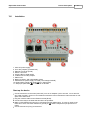
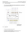
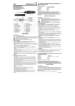
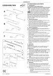
Installation
1. 230V AC power supply
2. Four relay outputs ( potential-free)
3. Ethernet connector (RJ45)
4. Sensor connector
5. Activity LED for digital inputs
6. 4 status LED for relay outputs
7. Status LED
8. Button for Select, OK or Bootloader mode
9. Alternative low power supply LV PWR (Low Voltage PoWeR)
10. Eight passive inputs (with GND ( ) for 2 inputs each)
11. Stop input (with GND ( )) to switch-off of all relais
Start-up the device
Connect the device to the mains (230V AC) or to an AC Adaptor (10V to 24V AC, 12V to 28V DC,
at 4 watts of power). Under no circumstances should the unit be fed with the mains and the AC Adaptor at the same time!
Plug the network cable into the Ethernet socket (RJ45) .
Connect the relay to the loads that should be be operated.
Make contact between the lines to be monitored and the digital inputs. To close an input circuit
there has to be a connection between a ground pin ( ) and the respective input pin has to be
made.
Connect the sensor (if any) to the device.
Expert Net Control 2301
1.5
Device Description
7
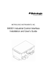
Connection Example
Here an example of a block diagram in which the device is supplied with 230V AC, and four AC loads
(L1 - L4) are connected. In addition, the inputs are joined to eight switches (S1 - S8), and the stop input is connected to the push-button PB1.
1.6
Status LED
The Status LED shows different states of the device:
red: Device is not connected to the Ethernet
orange: Device is connected to the Ethernet, TCP/IP settings are not allocated
green: Device is connected to the Ethernet, TCP/IP settings allocated
periodic blinking: Device is in Bootloader mode.
Expert Net Control 2301
1.7
Device Description
8
Digital Inputs
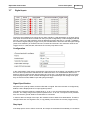
The device has 8 digital inputs, which have a value of HIGH or LOW depending on the input signal.
This value can also be taken inverted from the input (see Configuration). LOW is displayed red with
text "off / open" in the web interface, HIGH is displayed as green with text "on / closed". In addition,
the number of signal changes ("toggle count") are counted and the time since the last signal change
("time since transition") is measured as hours, minutes and seconds. The maximum value for the
"toggle count" is 4,294,967,295, after which the counter jumps back to zero.
Configuration
In the configuration of the device, the behavior of the inputs can be changed. It is possible to change
the name of an input and the standard text for HIGH and LOW. This customization allows for example to specify a water sensor with the states "dry" and "wet". The dependence of the input value
from the physical input can be inverted. Messages can be generated upon the change of an input,
they are sent as emails, SNMP-Traps and syslog messages.
Signal Specification
All inputs have a pull-up resistor, and are HIGH with no signal. Since the inversion is configured by
default, LOW is displayed when no input signal is present.
The value is measured LOW at a voltage level of -1V to 1V, the and measured HIGH between 2V
and 30V. The voltage range of the inputs is specified from -1V to 30V. The inputs are not potentialfree, the common ground "GND" must therefore be connected.
In order to detect a change of the input, the condition must be stable for at least 500ms. Therefore,
changes faster than 1Hz signal are not, or only partially covered from the counter ("toggle count").
Stop Input
If the Stop Input is set to LOW for a second, all 4 relays are switched off immediately. If a shutdown
Expert Net Control 2301
Device Description
9
was initiated, and the Stop Input goes back to HIGH for a second, the relay will re-activate as if the
device is started again. See Initialization Initialization status and Initialization delay in the chapter
"Configuration - Output Ports". The Stop Input is not inverted from the configuration.
Bootloader Mode
1.8
Certain actions can, for safety reasons, only be carried out if the device is in bootloader mode. The
following operations are possible only in Bootloader Mode:
Firmware Update
Configuration with GBL_Conf.exe
Factory Reset
Activation of the Bootloader Mode
via push button:
Hold both buttons for 3 seconds (only if the device has 2 buttons)
or
Remove the power supply
Hold down the button (or the "Select" button for devices with 2 buttons). If the push button is recessed, use a pin or paper clip
Connect the operating voltage
by Software: (only if "Enable FW to BL" was previously activated in GBL_Conf.exe)
Start GBL_Conf.exe
Do a network search with the "Search" menu action
Activate in menu "Program Device" the item "Enter Bootloader"
Whether the device is in bootloader mode, is indicated by the flashing of the status LED, or it is
shown in GBL_Conf.exe, after a renewed device search, with the appendix "BOOT-LDR" after the
device name. In bootloader mode the program GBL_Conf.exe can disable the password and the IP
ACL, perform a firmware update, and restore the factory settings.
Activation of the bootloader mode and an abandonment of the bootloader does not change
the state of the power or output ports as long as the supply voltage is maintained.
Abandonment of the Bootloader Mode
via push button:
Hold both buttons for 3 seconds (only if the device has 2 buttons)
or
Remove and connect the power supply without operating a button
by Software:
Start GBL_Conf.exe
Do a network search with the "Search" menu action
In menu "Program Device" activate the item "Enter Firmware"
Expert Net Control 2301
Device Description
10
Factory Reset
If the device is in bootloader mode, it can always be put back to its factory default. All TCP / IP settings are reset in this operation.
via push button:
Activate the Bootloader Mode of the device
Hold down the button (or the "Select" button for devices with 2 buttons) for 6 seconds. If the push
button is recessed, use a pin or paper clip
The status LED will blink in a fast rhythm, please wait until the LED blinks slowly (about 5 seconds)
by Software:
Activate the Bootloader Mode of the device
Start GBL_Conf.exe
In menu "Program Device" activate the item "Reset to Fab Settings"
The status LED will blink in a fast rhythm, please wait until the LED blinks slowly (about 5 seconds)
1.9
Firmware-Update
To perform a firmware update, the program GBL_Conf.exe and the latest firmware is needed.
Enable the bootloader mode (see Chapter Bootloader Mode)
Start GBL_Conf.exe
Select the device for which a firmware update is to be performed
Click "Program Device" and then select there "Firmware Update"
Specify the firmware file that should be uploaded
Upon completion of the update process, please start the new firmware of the device. You can do this
by simply leaving the bootloader mode.
A firmware update, unlike other functions, is not sent as a network broadcast. Therefore, the device
must have a valid IP address and a valid netmask before the firmware update. If necessary, please
correct the entries in GBL_Conf.exe in bootloader mode and save them with "Save Config".
If after a firmware update, the web page is not displayed correctly anymore, this may be related to the
interaction of Javascript with an outdated browser cache. Not always helps a Ctrl-F5, it is recommended that you manually delete the cache in the browser options. Alternatively, you can test start the
browser in "private mode".
Expert Net Control 2301
1.10
Device Description
Technical Specifications
Interfaces
Network connectivity
Protocols
Power Supply
1 x Ethernet port (RJ45)
1 x Connector for mains supply (230V AC)
1 x Connector for AC Adaptor (12V DC, 0,5A). 12V DC power
supply
12 x screw terminal with 8 inputs and 4 x GND
8 x screw terminal with 4 make contacts (230V AC 16A,
24V DC 10 A)
1 x Mini-DIN socket for external sensor
10/100 MBit/s 10baseT Ethernet
TCP/IP, HTTP, DHCP, ICMP,
SNMP v1/v2c + traps, Syslog, SMTP
internal power supply (230V AC)
alternative: 10V to 24V AC, 12V to 28V DC (at 4 watts of power)
Environment
Operating temperature
Storage temperature
Humidity
Case
Measurements
Weight
1.11
11
0°C to 50°C
-15°C to 60°C
10% to 85%
plastics grey
105mm x 70mm x 90mm (L x H x D)
approx. 300g
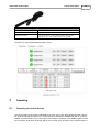
Sensor
An external sensor can be connected to the Expert Net Control 2301. The following sensors are currently available:
Temperature-Sensor 7001
Cable length
˜ 2m
Connector
Mini-DIN
Measurement range
-20°C to +80°C at ±2°C (maximum) and ±1°C (typical)
Expert Net Control 2301
Device Description
12
Humidity/Temperature-Sensor 7002
Cable length
˜ 2m
Connector
Mini-DIN
Measurement range
Temp: -20 to +80°C, ±0,5°C (maximum) and ±0,3°C (typical)
Humidity: 0-100%, ±3% (maximum) and ±2% (typical)
The sensor is automatically detected after connect.
2
Operating
2.1
Operating the device directly
The current status of the output is indicated by the color of the LED. Red indicates that the output is
off, green shows that the output is on. On the device are the buttons "select" and "ok". If you press
"select", the LED will blink for the first output, ie the output is selected. Press "select" again to select
the next output. Hold down the button "ok" for two seconds, then the status of the selected output is
Expert Net Control 2301
Operating
13
toggled.
2.2
Operating by Webinterface
Access the web interface: http://"IP-address" and log-in.
The website offers an overview of the port status, measurements and sensors, if they are connected.
Furthermore, here are buttons to control the state of the ports. The ports can be switched manually
with the "On" and "Off" buttons. If the port is turned on, it can be turned off by pressing the "Reset"
button, until after a delay it turns itself on again. The delay time is determined by the parameter Reset
Duration, which is described in the chapter about configuration via web interface.
Batchmode
Each individual port can be set for a selectable period of time to the state "switch on" or "switch off".
After the selected time they are automatically switched to the second preselected state.
Expert Net Control 2301
Operating
14
Optionally the device can be switched via a Perl script or external tools like wget. More information is
available on our support wiki at www.gude.info / wiki.
2.3
Using the Serial Interface
There is a serial connection alternatively to the Ethernet port, where the power ports can be switched.
You will need a terminal program such as the free supplied Windows HyperTerminal.
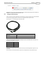
Connect your PC to the device via the serial cable 7990.
Serial Cable 7990
Cable length
˜ 2m
Device Connector
Mini-DIN
PC Connector
D-Sub 9-pin socket
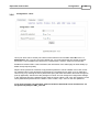
Start your terminal program and select the COM port to which the RS232 cable is connected. Use
the following settings ?
for the serial port:
Baudrate
Databits
Parity
Stoppbits
Flow Control
115200
8
No
1
No
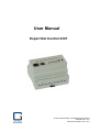
If you do not use HyperTerminal, please make sure that your terminal application supports VT100
commands.
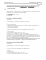
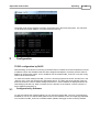
If the connection is successful the device reports as in the figure below. Press ENTER to login.
Expert Net Control 2301
Operating
15
The power ports can be toggled by pressing numerical keys in the terminal program. The character
"z" will show the network settings. To logout, press the Esc key.
3
Configuration
TCP/IP configuration by DHCP
After switching on the device is scanning on the Ethernet for a DHCP server and requests an unused
IP address. Check the IP address that has been assigned and adjust if necessary, that the same IP
address is used at each restart. To turn off DHCP use the software GBL_Conf.exe or use the configuration via the web interface.
To check the network settings with GBL_Conf.exe, start the program and choose "All Devices" in the
"Search" menu. From the list select the appropriate device. The lower part of the left half of the window now shows the current network settings of the device. If the IP address is displayed with the default settings (192.168.0.2), either no DHCP server is present on the network, or there could be no
free IP address assigned to it.
3.1
Configuration by Software
To view and change the network settings, you can use the program GBL_Conf.exe. The program is
available for free on our website www.gude.info and is also available on the accompanying CD-ROM.
You can also use GBL_Conf.exe to install firmware updates and trigger a reset to factory defaults.
Expert Net Control 2301
Configuration
16
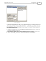
Interface GBL_Conf
To check the network settings with GBL_Conf.exe, start the program and choose "All Devices" in the
"Search" menu. From the list select the appropriate device. The lower part of the left half of the window now shows the current network settings of the device. If the IP address is displayed with the default settings (192.168.0.2), either no DHCP server is present on the network, or there could be no
free IP address assigned to it.
Activate the Bootloader Mode (see Chapter Bootloader Mode) and choose in menu "Search" the
item "Bootloader-Mode Devices only"
Enter the desired settings in the edit window and save them with "Save Config".
Deactivate the boot loader mode for the changes to take effect. Select again "All Devices" in the
"Search" menu of GBL_Conf.exe. The new network configuration is now displayed.
Expert Net Control 2301
3.2
Configuration via Webinterface
Access the web interface: http://"IP-address" and log-in.
Use the "Configuration" Tab to enter the configuration menu.
Configuration
17
Expert Net Control 2301
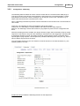
3.2.1
Configuration
18
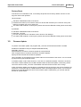
Configuration - Output Ports
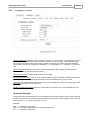
Choose Output Port to configure: This field is used to select the output ports to be configured.
Label: You can assign a name up to 15 characters for each of the output ports. Using the name, an
identification of the the device connected to the port can be facilitated. This name is also shown on
the status page.
Start-up Monitoring
It is important, that if necessary the condition of the output ports can be restored after a power failure.
Therefore each port can be configured with Initialization status to a specific start-up state. This startup sequence can be carried out delayed by the parameter Initialization Delay. There is in any case a
minimum one-second delay between switching of ports.
Initialization status: This is the port state (on, off, remember last state) the port should be set when
the device is turned on. The setting "remember last state" saves the last manually set state of the output port in the EEPROM.
Initialization delay: Here can be configured how long the port should wait to switch to its defined state
after the device is turned on. The delay may last up to 8191 seconds. This corresponds to a period of
approx. two hours and 20 minutes. A value of zero means that the initialization is off.
Repower delay: When this feature is enabled (value greater than 0), the output port will switch itself
on again a specified time after it has been disabled. Unlike the "Reset" button this function applies to
all switch actions, including SNMP, or an optional serial interface.
Reset Duration: When the "Reset" button is triggered, the device turns the output port off, waits for
the time entered here (in seconds) and turns the output port on.
Expert Net Control 2301
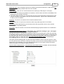
3.2.2
Configuration
19
Configuration - Watchdog
The watchdog feature enables to monitor various remote devices. Therefore either ICMP pings or
TCP pings are sent to the device to be monitored. If these pings are not answered within a certain
time (both the time and the number of attempts can be set), the port is reset. This allows e.g. to
switch other devices that are connected via the relay.
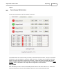
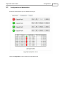
When a watchdog is activated it presents various information in the Control Panel. The information is
color-coded.
Green text: The watchdog is active and regularly receives ping replies.
Orange text: The watchdog is currently enabled, and waits for the first Ping response.
Red text: The watchdog is active and receives no ping replies anymore from the configured IP address.
After the watchdog has been enabled, the display remains orange until the watchdog receives a ping
response for the first time. Only then the watchdog is activated. Even after triggering a watchdog and
a subsequent Output Port reset, the display will remain orange until the device is rebooted and responds again to ping requests. This will prevent a premature watchdog reset of the port, e.g. when a
server needs a long time for a file check.
You can monitor devices on your own network, as well as devices on an external network, e.g. the
operating status of a router.
Enable watchdog: Enables the watchdog function for this Output Port.
Expert Net Control 2301
Configuration
20
Watchdog action: When selecting reset, the Port will be turned off and switched on again after a Reset Duration. The setting off leaves the Port in the off state.
Watchdog type: Here you can choose between the monitoring by ICMP pings or TCP pings.
ICMP Pings: The classic ping (ICMP echo request). It can be used to check the accessibility of network devices (for example, a server).
TCP Pings: With TCP pings, you can check if a TCP port on the target device would accept a TCP
connect. Therefore a non-blocked TCP port should be selected. A good choice would be port 80
for http or port 25 for SMTP.
Hostname: The name or IP address of the monitored network device.
TCP port: Enter the TCP port to be monitored. When using ICMP pings this is not needed.
Ping interval: Select the frequency (in seconds) at which the ping packet is sent to each network
device to check its operating status.
Ping retries: After this number of consecutive unanswered ping requests the device is considered inactive.
retry BOOTING after RESET failure: !!! Be careful, only switch this setting to "yes", if the appliance to be monitored never requires a long boot time !!!
Normally (this option no selected) the watchdog monitors the connected device. When the watchdog
is activated, because the device is not answering, the pre-selected watchdog action is executed. Now
the watchdog waits until the monitored device is answering to pings again. After this the watchdog is
armed again. When you select the option retry BOOTING after RESET failure, the watchdog is
armed directly after the watchdog action is executed.
This option has the following pitfall: If at the Port to be monitored a server connected, that is in need
for a long boot process, because it is doing a file system check, the server would probably exceed the
tripping time of the watchdog. The server would be switched off and on again, and the file system
check is restarted. This would be repeated endlessly.
retry Boot after N ping timeouts: If retry BOOTING after RESET failure is enabled, the device waits N
Ping intervals until the connected device is switched off and on again.
Expert Net Control 2301
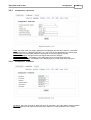
3.2.3
Configuration
21
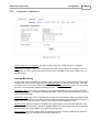
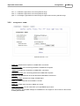
Configuration - Input Ports
Label: This input mask can assign digital inputs to individual names that are easier to remember,
such as "Entrance" or "Basement Window", etc. This name is also displayed on the status page.
Inverted input: The association between LOW and HI to the input signal is inverted.
Generate Messages: Changes of the input signals will produce messages.
Input HI text message: Text display on the status page for a HI signal at the input port.
Input LOW text message: Text display on the Status page for a LOW signal at the input port.
3.2.4
Configuration - IP Address
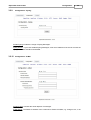
Hostname: Here you can enter a name with up to 15 characters. This name will be used for registration on the DHCP server. Special characters and umlauts can cause problems in the network.
Expert Net Control 2301
Configuration
22
IP Address: The IP address of the device.
Netmask: The network mask used in the network.
Gateway address: The IP address of the gateway.
Use DHCP: Select "yes" if the TCP/IP settings should be obtained directly from the DHCP server:
When the function is selected, each time the device powers up it is checked if a DHCP server is
available on the network. If not, the last used TCP/IP setting will be used further.
All IP changes will take effect directly, there is no need for a restart of the firmware.
3.2.5
Configuration - IP ACL
Reply ICMP ping requests: If you enable this feature, the device responds to ICMP pings from the
network.
Enable IP filter: Enable or disable the IP filter here. The IP filter represents an access control for incoming IP packets.
Please note that when IP access control is enabled DHCP and SNMP only work if the appropriate servers and clients are registered in the IP access control list.
IP Access Control List
The IP Access Control List (ACL IP) is a filter for incoming IP packets. If the filter is active, you can
only connect to hosts and subnets whose IP addresses are entered in the list.
Examples:
Entry in the IP ACL
Meaning
192.168.0.123
the PC with IP Address „192.168.0.123" can access the device
192.168.0.1/24
all devices of subnet „192.168.0.1/24“ can access
If you choose a wrong IP ACL setting and locked yourself out, please activate the Bootloader Mode
and use GBL_Conf.exe to deactivate the IP ACL.
Expert Net Control 2301
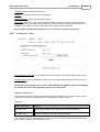
3.2.6
Configuration
23
Configuration - HTTP
HTTP port: Here can be set the port number of the internal HTTP. Possible values ?
are from 1 to
65534 (default: 80). If you do not use the default port, you must append the port number to the address with a colon to address the device from a web browser. Such as: "http://192.168.0.2:800"
Enable auto refresh HTML: If this is activated, the information of the status page is automatically updated via http request (AJAX).
Require HTTP password: If desired, a http password protection can be enabled. In this case, an admin password and a user password can be assigned. The password can have up to 15 characters.
User can log in by entering the user's password to query the status information and make changes to
ports (if applicable). Admins have the privileges of a User and can change the Configuration settings.
In the username field of the password input mask the names "admin" and "user" are supported. In the
factory defaults the password for the admin is set to "admin" resp. "user" for the user password.
If you have forgotten your password, please activate the bootloader mode and then turn off
the password prompt in GBL_Conf.exe.
Expert Net Control 2301
3.2.7
Configuration
24
Configuration - Sensors
Choose sensor port: Selects a type of sensor to configure it. The first digit "1" indicates the number of
the sensor port (only important for devices with more than one sensor port). This is followed by the
sensor name (eg 7002 for the hybrid sensor), a letter for the sub-type sensor and the changeable
sensor name. The sensor subtypes are defined as: "T" = temperature, "H" = humidity, "I" = sensor input.
Sensor Name: Changeable name for this sensor. Temperature and humidity can have different
names, even if they are from the same sensor.
Generate messages: Enables the generation of messages.
Maximum/Minimum value: Here you can choose whether, and at what Maximum/Minimum temperature or humidity measurements limits the alerts are send via SNMP traps, syslog or email.
Hysteresis: This is the distance between the value that is signaling an overrun of a limit and the value
that signals an underrun of the same limit.
Min/Max measurement period: Selects the time range for the sensor min / max values ?
on the overview web page.
Hysteresis Example:
A Hysteresis value prevents that too much messages are generated, when a sensor value is jittering
around a sensor limit. The following example shows the behavior for a temperature sensor and a hysteresis value of "1". An upper limit of "50 °C" is set.
Example:
49.9 °C - is below the upper limit
50.0 °C - a message is generated for reaching the upper limit
50.1 °C - is above the upper limit
Expert Net Control 2301
Configuration
25
...
49.1 °C - is below the upper limit, but in the hysteresis range
49.0 °C - is below the upper limit, but in the hysteresis range
48.9 °C - a message is generated for underrunning the upper limit inclusive hysteresis range
...
3.2.8
Configuration - SNMP
SNMP-get: Enables the acceptance of SNMP-GET commands.
Community public: The community password for SNMP GET requests.
SNMP-set: Enables the acceptance of SNMP-SET commands.
Community private: The community password for SNMP SET requests.
MIB table: The download link to the text file with the MIB table for the device.
Send SNMP traps: Activates the usage of SNMP traps.
SNMP v1: SNMP traps are sent in SNMP v1 format.
SNMP v2c: SNMP traps are sent in SNMP v2c format.
SNMP trap receiver: You can insert here up to eight SNMP trap receiver.
More information about SNMP settings are available from our support or can be found on the Internet
at www.gude.info/wiki.
Expert Net Control 2301
3.2.9
Configuration
26
Configuration - Syslog
Enable Syslog: Enables the usage of Syslog Messages.
Syslog Server: If you have enabled Syslog Messages, enter the IP address of the server to which the
syslog information should be transmitted.
3.2.10 Configuration - E-Mail
Enable E-Mail: Activates the email dispatch of messages.
E-Mail Server: The SMTP IP-address of the e-mail server. Either as FQDN, e.g: "mail.gmx.net", or as
Expert Net Control 2301
Configuration
27
IP-address, e.g: "213.165.64.20". If required, attach a designated port, e.g: "mail.gmx.net:25".
Sender address: The e-mail address of the sender.
Recipient address: The e-mail address of the recipient.
Enable authentification: Select this option if the e-mail server requires authentication.
Username: User name that is registered with the SMTP e-mail server.
Set new password: Enter the password for the login to the e-mail server.
Repeat password: Enter the password again to confirm it.
4
Protocols
4.1
SNMP
SNMP can be used to obtain status information via UDP (port 161). Supported SNMP commands
are:
GET
GETNEXT
GETBULK
SET
To query via SNMP you need a Network Management System, such as HP OpenView, OpenNMS,
Nagios, etc., or the command line tools of the Net-SNMP software.
SNMP-communities
SNMP authenticates requests by communities. A community is a string that acts like a password for a
read or a write SNMP access. Since these passwords are sent unencrypted and are easily intercepted with IP sniffers, it is recommended to use a safe network structure (DMZ) when security is required.
MIB
The values ?
that can be read from the device or changed, the so-called "Managed Objects", are described in Management Information Bases (MIBs). The MIB table is build of substructures that are
called OIDs (Object Identifiers). An OID number indicates the location of a value within the MIB tree.
Each OID may alternatively be referred to with its symbol name (subtree name).
SNMP Traps
SNMP Traps are system messages that are sent via the SNMP protocol to different recipients. SNMP
traps are triggered by the following events:
Switching of digital output ports
State change of digital input ports
Exceeding of the max / min values ?
of attached sensors
Expert Net Control 2301
4.2
Protocols
28
Syslog
Syslog messages are simple text messages that are sent via UDP to a syslog server. Under Linux,
normally a syslog daemon is already running (eg. syslog-ng), for Microsoft Windows systems some
freeware programs are available on the market. The syslog messages are sent for the following
events:
Switching of digital output ports
State change of digital input ports
Exceeding of the max / min values ?
of attached sensors
4.3
Email
Currently, only SMTP servers are supported, that are offering no authentication (open-relay) or unencrypted authentication (PLAIN). An encrypted authentication to the SMTP server is not possible.
An experienced user can learn whether the desired SMTP server understands the PLAIN authentication, by sending the string "EHLO localhost" with Telnet to the server. Here's an example:
$ telnet smtp.1und1.com 25
Trying 212.227.15.129...
Connected to smtp.1und1.com.
Escape character is '^]'.
220 smtp.1und1.com (mreu3) Welcome to Nemesis ESMTP server
EHLO localhost
<---- *TYPE* *THIS*
250-smtp.1und1.com
250-STARTTLS
250-AUTH LOGIN PLAIN
<---- *PLAIN* *SUPPORTED!*
250-AUTH=LOGIN PLAIN
250-SIZE 120000000
250 HELP
5
Support
You will find the latest product software on our website at www.gude.info available for download. If
you have further questions about installation or operation of the unit, please contact our support
team. Furthermore, we present in our support wiki at www.gude.info/wiki FAQs and configuration examples.
5.1
Contact
Gude Analog- und Digitalsysteme GmbH
Eintrachtstraße 113
50668 Cologne
Germany
Phone: +49-221-912 90 97
Fax: +49-221-912 90 98
E-Mail: [email protected]
Internet: www.gude.info
Managing Director: Dr.-Ing. Michael Gude
District Court: Köln, HRB-Nr. 17 7 84
WEEE-number: DE 58173350
Value added tax identification number (VAT): DE 122778228
Expert Net Control 2301
5.2
Support
29
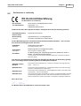
Declarations of conformity
EG Konformitätserklärung
EC Declaration of Conformity
Der Hersteller
The manufacturer
Gude Analog- und Digitalsysteme GmbH
Eintrachtstr. 113
50668 Köln (Deutschland)
erklärt hiermit, dass die folgenden Produkte / hereby declares that the following products
Produktbezeichnung
Product name
Expert Net Control 2301
Beschreibung
IP gesteuertes Ein- und Ausgabegerät
IP remote controlled input / output device
Description
mit den Bestimmungen der nachstehenden EU-Richtlinien übereinstimmen / are in accordance with the following European directives
2006/95/EG
Niederspannungsrichtlinie
2006/95/EC
Low Voltage Directive (LVD)
2004/108/EG
Elektromagnetische Verträglichkeit (EMV)
2004/108/EC
Electromagnetic Compatibility (EMC)
2011/65/EU
zur Beschränkung der Verwendung bestimmter gefährlicher Stoffe in
Elektro- und Elektronikgeräten (RoHS)
on the restriction of the use of certain hazardous substances in electrical and electronic
equipment (RoHS)
und dass die nachstehenden harmonisierten Europäischen Normen zur Anwendung gelangt
sind. / and comply with the following harmonised European standards.
EN 60950-1:2006 /
AC:2011
Einrichtungen der Informationstechnik – Sicherheit / Information technology equipment –
Safety - - Article 3.1.a
EN 55022:2010
Einrichtungen der Informationstechnik – Funkstöreigenschaften / Information technology
equipment – Radio disturbance characteristics
EN 55024:2010
Einrichtungen der Informationstechnik - Störfestigkeitseigenschaften / Information technology equipment - Immunity characteristics
EN 50581:2012
Technische Dokumentation zur Beurteilung von Elektro- und Elektronikgeräten hinsichtlich
der Beschränkung gefährlicher Stoffe / Technical documentation for the assessment of
electrical and electronic products with respect to the restriction of hazardous substances
Köln, 09.07.2013
Dr. Michael Gude, Geschäftsführer / General manager, CEO
Expert Net Control 2301
© 2014 Gude Analog- und Digitalsysteme GmbH
03.10.2014