1
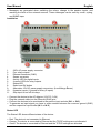
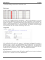
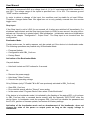
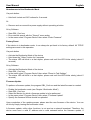
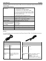
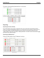
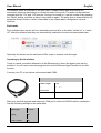
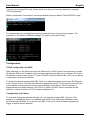
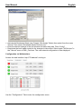
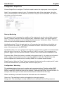
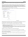
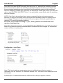
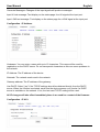
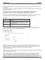
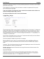
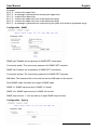
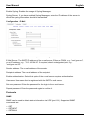
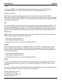
IPower Control 4 DIN s
User Manual
Eng lis h
No. 32650
www.lindy.com
© LINDY ELECTRONICS LIMITED & LINDY-ELEKTRONIK GMBH - FIRST EDITION (March 2014)
Table of Contents
User Manual English............................................................................................................. 1
Device Description ....................................................................................................................... 2
Safety Advice ........................................................................................................................... 2
Package Contents .................................................................................................................... 2
Description ............................................................................................................................... 2
Installation .................................................................................................................................... 2
Status LED ............................................................................................................................... 2
Digital Inputs............................................................................................................................. 3
Bootloader Mode ...................................................................................................................... 4
Firmware-Update ...................................................................................................................... 5
Technical Specifications ........................................................................................................... 6
Sensor ...................................................................................................................................... 6
Operating ..................................................................................................................................... 7
Operating the device directly .................................................................................................... 7
Operating by Webinterface ....................................................................................................... 7
Operating by Serial Interface .................................................................................................... 8
Configuration................................................................................................................................ 9
Configuration by Software ........................................................................................................ 9
Configuration via Webinterface .............................................................................................. 10
Configuration - Output Ports ............................................................................................... 11
Configuration - Watchdog ................................................................................................... 11
Configuration - Input Ports .................................................................................................. 13
Configuration - IP Address .................................................................................................. 14
Configuration - IP ACL ........................................................................................................ 14
Configuration - HTTP .......................................................................................................... 15
............................................................................................................................................ 15
Configuration - Sensors ...................................................................................................... 16
............................................................................................................................................ 16
Configuration - SNMP ......................................................................................................... 17
............................................................................................................................................ 17
Configuration - Syslog......................................................................................................... 17
Configuration - E-Mail ......................................................................................................... 18
Protocols .................................................................................................................................... 18
SNMP ..................................................................................................................................... 18
Syslog..................................................................................................................................... 19
Email ...................................................................................................................................... 19
User Manual
English
Device Description
Safety Advice
• The device must be installed by a qualified person according to the following installation and
operating instructions in this manual.
• The manufacturer does not accept responsibility in case of improper use of the device and
particularly any use of equipment that may cause personal injury or material damage.
• The device contains no user-maintainable parts. All maintenance has to be performed by
trained service personnel.
• This device contains potentially hazardous voltages and should not be opened or
disassembled.
• The device should only be connected to 230V AC (50Hz or 60 Hz) power supply sockets.
• The power cords, plugs and sockets have to be in good condition. Always connect the device
to properly grounded power sockets.
• The device is intended for indoor use only. DO NOT install them in an area where excessive
moisture or heat is present.
• Because of safety and approval issues you are not allowed to modify the device without our
permission.
• Please also read the safety advice and manuals of connected devices.
• The device is NOT a toy. It must be used or stored out of the range of children.
• Plastics must be stored out of the range of children. Please recycle the package materials.
• In case of further questions, about installation, operation or usage of the device, which are
not clear after reading the manual, please contact our support team.
• Never leave connected equipment unattended that can cause damage.
• Connect only electrical devices that do not have limited on-time. I.e. in case of failure, all
connected appliances have to cope with a continuous on-time without causing damage.
• The unit can also be connected to low voltage. Under no conditions connect it simultaneously
to both voltage sources.
Package Contents
• IPower Control 4 DIN s
• CD-ROM with manual
Description
The IPower Control 4 DIN s is a multipurpose device that is suitable for switching voltages and
to monitor passive inputs. It has the following features:
• Suitable for top hat rail mounting
• Switching of high voltages (230V AC 16A, 24V DC 10A) with 4 relay outputs
• Monitoring of 8 passive inputs suitable for door contacts, level indicators, etc.
• Can connect to external sensors to measure temperature and humidity values
• Control and monitor the device via Ethernet with an integrated web server and SNMP (v1 and
v2c)
User Manual
English
• Messages are generated when switching the relays, change to the passive inputs, and
reaching the limits of the external sensors. These messages can be sent by e-mail, syslog,
and SNMP traps
Installation
1.
2.
3.
4.
5.
6.
7.
8.
9.
10.
11.
•
•
•
•
230V AC power supply connector
Four relay outputs
Ethernet connector (RJ45)
Sensor connector
Activity LED for digital inputs
4 control LEDs for relay outputs
Status LED
Select and OK button
Alternative 12V DC power supply connectors (Low Voltage Power)
8 passive inputs (1 ground for every 2 inputs)
Stop input to turn off all relays
Connect the device to the AC Adaptor (12V DC, 0,5A)
Plug the network cable into the Ethernet (RJ45) port
Connect the devices to be monitored to the passive input sockets (IN 1 or IN 2)
To generate an input signal you have to make contact between the common ground (GND)
and the respective input socket (IN 1 or IN 2)
Status LED
The Status LED shows different states of the device:
• Red: The device is not connected to Ethernet
• Orange: The device is connected to Ethernet but the TCP/IP settings are not allocated
• Green: The device is connected to Ethernet and the TCP/IP settings are allocated
User Manual
English
• Intermittent blinking: The device is in Bootloader mode
Digital Inputs
The device has 8 digital inputs, which have a value of HIGH or LOW depending on the input
signal. This value can also be inverted from the input (see Configuration). LOW is displayed as
red with text "off/open" in the web interface, HIGH is displayed as green text "on/closed". The
number of signal changes/toggle count are counted since the last signal change/time since
transition and are measured as hours, minutes and seconds. The maximum value for the toggle
count is 4,294,967,295, after which the counter jumps back to zero.
Configuration
In the configuration of the device, the behavior of the inputs can be changed. It is possible to
change the name of an input and the standard text for HIGH and LOW. This customization
allows for example to specify a water sensor with the states "dry" and "wet". The dependence of
the input value from the physical input can be inverted. Messages can be generated upon the
change of an input, they are sent as emails, SNMP-Traps and syslog messages.
Signal Specification
All inputs have a pull-up resistor, and are HIGH with no signal. Since the inversion is configured
by default, LOW is displayed when no input signal is present.
User Manual
English
The value is measured LOW at a voltage level of -1V to 1V and measured HIGH between 2V
and 30V. The voltage range of the inputs is specified from -1V to 30V. The common ground
"GND" must be connected.
In order to detect a change of the input, the condition must be stable for at least 500ms.
Therefore, changes faster than 1Hz signal are not or only partially covered from the counter
toggle count.
Stop Input
If the Stop Input is set to LOW for one second, all 4 relays are switched off immediately. If a
shutdown was initiated, and the Stop Input goes back to HIGH for one second, the relay will reactivate as if the device is started again. See Initialisation - Initialisation status and Initialisation
delay in the chapter "Configuration - Output Ports". The Stop Input is not inverted from the
configuration.
Bootloader Mode
Certain actions can, for safety reasons, only be carried out if the device is in bootloader mode.
The following operations are possible only in Bootloader Mode:
• Firmware Update
• Configuration with GBL_Conf.exe
• Factory Reset
Activation of the Bootloader Mode
Via push button:
• Hold both “select and OK” buttons for 3 seconds
Or
• Remove the power supply
• Hold down "Select" button.
• Connect the operating voltage
Or by Software (only if "Enable FW to BL" was previously activated in GBL_Conf.exe)
• Start GBL_Conf.exe
• Do a network search with the "Search" menu action
• In the menu select "Program Device" then select "Enter Bootloader"
If the device is in bootloader mode it is indicated by the flashing of the status LED, or it is shown
in GBL_Conf.exe after a renewed device search with the appendix "BOOT-LDR" after the
device name. In bootloader mode the program GBL_Conf.exe can disable the password and
the IP ACL, perform a firmware update, and restore the factory settings.
Activation of the bootloader mode and an abandonment of the bootloader, does not
change the state of the power or output ports as long as the supply voltage is
maintained.
User Manual
English
Abandonment of the Bootloader Mode
Via push button:
• Hold both “select and OK” buttons for 3 seconds
Or
• Remove and re-connect the power supply without operating a button
Or by Software
• Start GBL_Conf.exe
• Do a network search with the "Search" menu action
• In the menu select "Program Device" then select "Enter Firmware"
Factory Reset
If the device is in bootloader mode, it can always be put back to its factory default. All TCP/IP
settings are reset in this operation.
Via push button
• Activate the Bootloader Mode of the device
• Hold down the "Select" button for 6 seconds.
• The status LED will blink in a fast rhythm, please wait until the LED blinks slowly (about 5
seconds)
Or by Software
•
•
•
•
Activate the Bootloader Mode of the device
Start GBL_Conf.exe
In the menu select "Program Device" then select "Reset to Fab Settings"
The status LED will blink in a fast rhythm, please wait until the LED blinks slowly (about 5
seconds)
Firmware-Update
To perform a firmware update, the program GBL_Conf.exe and the latest firmware is needed.
•
•
•
•
•
Enable the bootloader mode (see Chapter “Bootloader Mode”)
Start GBL_Conf.exe
Select the device for which a firmware update is to be performed
In the menu select "Program Device" then select "Firmware Update"
Specify the firmware file that should be uploaded
Upon completion of the update process, please start the new firmware of the device. You can
do this by simply leaving the bootloader mode.
A firmware update, unlike other functions, is not sent as a network broadcast. Therefore, the
device must have a valid IP address and a valid netmask before the firmware update. If
User Manual
English
necessary, please correct the entries in GBL_Conf.exe in bootloader mode and save them with
"Save Config".
Technical Specifications
Interfaces
Network connectivity
Protocols
Power Supply
Environment
• Operating temperature
• Storage temperature
• Humidity
Case
Measurements
Weight
1 x Ethernet port (RJ45)
1 x Connector for 230V AC Adaptor
1 x Connector for 12V DEC power supply
12 x Screw terminal with 8 inputs and 4 x GND
8 x Screw terminal with 4 make contacts (230V
AC 16A, 24V DC 10 A)
1 x Mini-DIN socket for external sensor
10/100 MBit/s 10baseT Ethernet
TCP/IP, HTTP, DHCP, ICMP,
SNMP v1/v2c + traps, Syslog, SMTP
Power supply (230V AC, 12V DC)
0°C to 50°C
-15°C to 60°C
10% to 85%
Grey plastic
105mm x 70mm x 90mm (L x H x W)
approx. 500g
Sensor
An external sensor can be connected to the IPower Control 4 DIN s. The following sensors are
currently available:
Temperature-Sensor 7001
Humidity/Temperature-Sensor 7002
Cable length
~2m
Cable length
~ 2m
Connector
Mini-DIN
Connector
Mini-DIN
Measurement -20°C to +80°C ±2°C
range
(maximum) and ±1°C
(typical)
Measurement Temp: -20 to +80°C, ±0,5°C
range
(maximum) and ±0,3°C
(typical)
Humidity: 0-100%, ±3%
(maximum) and ±2% (typical)
User Manual
English
The sensor will automatically detected after it is connected.
Operating
Operating the device directly
The current status of the output is indicated by the color of the LED. Red indicates that the
output is off, green shows that the output is on. On the device are the buttons "select" and "ok".
If you press "select", the LED will blink for the first output, ie the output is selected. Press
"select" again to select the next output. Holding down the "ok" button for two seconds will toggle
the status of the selected output.
Operating by Webinterface
Access the web interface: http://"IP-address" and log-in.
User Manual
English
The website offers an overview of the port status, measurements and sensors that are
connected, there are also buttons to control the state of the ports. The ports can be switched
manually with the "On" and "Off" buttons. If the port is turned on, it can be turned off by pressing
the "Reset" button, until after a delay it turns itself on again. The delay time is determined by the
parameter Reset Duration, which is described in the chapter about configuration via web
interface.
Batchmode
Each individual port can be set for a selectable period of time to the state "switch on" or "switch
off". After the selected time they are automatically switched to the second preselected state.
Optionally the device can be switched via Perl script or external tools like wget.
Operating by Serial Interface
There is a serial connection alternative to the Ethernet port, where the power ports can be
switched. You will need a terminal program such as the Windows HyperTerminal to use this
function.
Connect your PC to the device via the serial cable 7990.
Serial Cable 7990
Cable length
≈ 2m
Device
Connector
Mini-DIN
PC Connector
D-Sub 9-pin socket
Start your terminal program and select the COM port to which the RS232 cable is connected.
Use the following settings for the serial port:
Baud-rate
115200
Data-bits
Parity
Stop-bits
Flow Control
8
No
1
No
User Manual
English
If you do not use HyperTerminal, please make sure that your terminal application supports
VT100 commands.
When a connection is successful, the device reports figures as below. Press ENTER to login.
The power ports can be toggled by pressing numerical keys in the terminal program. The
character "z" will show the network settings. To logout, press the Esc key.
Configuration
TCP/IP configuration by DHCP
After switching on, the device will scan the Ethernet for a DHCP server and request an unused
IP address. Check the IP address that has been assigned and adjust it if necessary.The same
IP address is used at each restart. To turn off DHCP use the software GBL_Conf.exe or use the
configuration via the web interface.
To check the network settings with GBL_Conf.exe, start the program and choose "All Devices"
in the "Search" menu. From the list select the appropriate device. The lower part of the left half
of the window now shows the current network settings of the device. If the IP address is
displayed with the default settings (192.168.0.2), either no DHCP server is present on the
network, or there could be no free IP address assigned to it.
Configuration by Software
To view and change the network settings, you can use the program GBL_Conf.exe. The
program is available for free on our website www.LINDY.com and is also available on the
accompanying CD-ROM. You can also use GBL_Conf.exe to install firmware updates and
trigger a reset to factory defaults.
User Manual
English
• Activate the Bootloader Mode (see Chapter “Bootloader” Mode) then select from the menu
"Search" then select "Bootloader-Mode Devices only"
• Enter the desired settings in the edit window and save them with "Save Config".
• Deactivate the boot loader mode for the changes to take effect. Select again "All Devices" in
the "Search" menu of GBL_Conf.exe. The new network configuration is now displayed.
Configuration via Webinterface
Access the web interface: http://"IP-address" and log-in.
Use the "Configuration" Tab to enter the configuration menu.
User Manual
English
Configuration - Output Ports
Choose Output Port to configure: This field is used to select the output ports to be configured.
Label: You can assign a name of up to 15 characters for each of the output ports. Using the
name, an identification of the the device connected to the port can be facilitated. This name is
also shown on the status page.
Start-up Monitoring
It is important, that if necessary the condition of the output ports can be restored after a power
failure. Therefore each port can be configured with “Initialisation status” to a specific start-up
state. This start-up sequence can be delayed by the parameter “Initialisation Delay”. There is a
minimum one-second delay between switching of ports.
Initialisation status: This is the port state (on, off, remember last state) the port should be set
when the device is turned on. The setting "remember last state" saves the last manually set
state of the output port in the EEPROM.
Initialisation delay: You can configure how long the port should wait to switch to its defined state
after the device is turned on. The delay may last up to 8191 seconds. This corresponds to a
period of approx. two hours and 20 minutes. A value of zero means that the initialization is off.
Re-power delay: When this feature is enabled (value greater than 0), the output port will switch
itself on again at a specified time after it has been disabled. Unlike the "Reset" button this
function applies to all switch actions, including SNMP or an optional serial interface.
Reset Duration: When the "Reset" button is triggered, the device turns the output port off, waits
for the time entered here (in seconds) and turns the output port on.
Configuration - Watchdog
The watchdog feature allows you to monitor various remote devices. Therefore either ICMP
pings or TCP pings are sent to the device to be monitored. If these pings are not answered
within a certain time (both the time and the number of attempts can be set), the port is reset. For
example; this allows you to switch other devices that are connected via the relay.
When a watchdog is activated it saves the information as color-coded text:
Green text: The watchdog is active and regularly receives ping replies
Orange text: The watchdog is currently enabled, and is waiting for the first Ping response
User Manual
English
Red text: The watchdog is active and has received no ping replies from the configured IP
address
After the watchdog has been enabled, the display remains orange until the watchdog receives a
ping response for the first time. Only then is the watchdog activated. Even after triggering a
watchdog and a subsequent Output Port reset, the display will remain orange until the device is
rebooted and responds again to ping requests. This will prevent a premature watchdog reset of
the port, e.g. when a server needs a long time for a file check.
You can monitor devices on your own network, as well as devices on an external network, e.g.
the operating status of a router.
Enable watchdog: Enables the watchdog function for this Output Port.
Watchdog action: When selecting “reset”, the Port will be turned off and switched on again after
the Reset Duration. Switching the setting to “off” will leave the Port in the off state.
Watchdog type: You can choose between monitoring by ICMP pings or TCP pings.
• ICMP Pings: The classic ping (ICMP echo request) can be used to check the accessibility of
network devices (for example, a server)
• TCP Pings: With TCP pings, you can check if a TCP port on the target device would accept a
TCP connect. Therefore a non-blocked TCP port should be selected. A good choice would
be port 80 for HTTP or port 25 for SMTP
Hostname: The name or IP address of the monitored network device.
TCP port: Enter the TCP port to be monitored. When using ICMP pings this is not needed.
Ping interval: Select the frequency (in seconds) at which the ping packet is sent to each network
device to check its operating status.
Ping retries: After the entered number of consecutive unanswered ping requests the device is
considered inactive.
User Manual
English
Retry BOOTING after RESET:Normally (this option has “no” selected) the watchdog monitors
the connected device. When the watchdog is activated, because the device is not answering,
the pre-selected watchdog action is executed. Now the watchdog waits until the monitored
device is answering to pings again. After this the watchdog is armed again. When you select the
option “retry BOOTING after RESET failure”, the watchdog is armed directly after the watchdog
action is executed.
NOTE: If the Port to be monitored has a server connected, that has a long boot process,
because it is doing a file system check, the server would probably exceed the tripping time of
the watchdog. The server would be switched off and on again, and the file system check is
restarted. This would be repeated endlessly.
Be careful, only switch this setting to "yes", if the appliance to be monitored never
requires a long boot time
Retry Boot after N ping timeouts: If “retry BOOTING after RESET” failure is enabled, the device
waits N Ping intervals until the connected device is switched off and on again. “N” denotes the
number of times to try this option.
Configuration - Input Ports
Label: This input mask can assign digital inputs to individual names that are easier to
remember, such as "Entrance" or "Basement Window", etc. This name is also displayed on the
status page.
Inverted input: The association between LOW and HI to the input signal is inverted.
User Manual
English
Generate Messages: Changes of the input signals will produce messages.
Input HI text message: Text display on the status page for a HI signal at the input port.
Input LOW text message: Text display on the status page for a LOW signal at the input port.
Configuration - IP Address
Hostname: You can enter a name with up to 15 characters. This name will be used for
registration on the DHCP server. Do not use special characters as this can cause problems in
the network.
IP Address: The IP address of the device.
Netmask: The network mask used in the network.
Gateway address: The IP address of the gateway.
Use DHCP: Select "yes" if the TCP/IP settings should be obtained directly from the DHCP
server: When the function is selected, each time the device powers up it checks if a DHCP
server is available on the network. If not, the last used TCP/IP setting will be used.
All IP changes will take effect immediately there is no need for a restart of the firmware.
Configuration - IP ACL
User Manual
English
Reply ICMP ping requests: If you enable this feature, the device responds to ICMP pings from
the network.
Enable IP filter: Enable or disable the IP filter here. The IP filter represents an access control for
incoming IP packets.
Note: When IP access control is enabled, DHCP and SNMP will only work if the
appropriate servers and clients are registered in the IP access control list.
The IP Access Control List (ACL IP) is a filter for incoming IP packets. If the filter is active, you
can only connect to hosts and subnets whose IP addresses are entered in the list.
Examples:
Entry in the IP
ACL
Meaning
192.168.0.123
the PC with IP Address "192.168.0.123" can
access the device
192.168.0.1/24
all devices of subnet "192.168.0.1/24" can
access
If you choose a wrong IP ACL setting and lock yourself out, please activate the Bootloader
Mode and use GBL_Conf.exe to deactivate the IP ACL.
Configuration - HTTP
HTTP port: You can set the port number of the internal HTTP. Possible values are from 1 to
65534 (default: 80). If you do not use the default port, you must change the port number to the
address with a colon to address the device from a web browser. Such as:
"http://192.168.0.2:800"
Enable auto refresh HTML: If this is activated, the information of the status page is automatically
updated via http request (AJAX).
Require HTTP password: If desired, http password protection can be enabled. In this case, an
admin password and a user password can be assigned. The password can have up to 15
characters. The user can log in by entering the user's password to query the status information
and make changes to ports (if applicable). Admins have the privileges of a User and can
User Manual
English
change the Configuration settings. The factory defaults password for the admin is set to "admin"
and for the user is "user".
Check password on start page: When this feature is enabled, the password will be queried
before displaying the login page.
If you have forgotten your password, please activate the bootloader mode and then turn
off the password prompt in GBL_Conf.exe.
All changes will take place after a reboot of the firmware.
Configuration - Sensors
Choose sensor port: Select a type of sensor to configure the port. The first digit "1" indicates the
number of the sensor port (only important for devices with more than one sensor port). This is
followed by the sensor name (e.g. 7002 for the hybrid sensor), a letter for the sub-type sensor
and the changeable sensor name. The sensor subtypes are defined as: "T" = temperature, "H"
= humidity, "I" = sensor input.
Sensor Name: Changeable name for this sensor. Temperature and humidity can have different
names, even if they are from the same sensor.
Generate messages: Enables the generation of messages.
Maximum/Minimum value: Here you can choose whether, and at what Maximum/Minimum
temperature or humidity measurements limits the alerts are sent via SNMP traps, syslog or
email.
Hysteresis: This is the distance between the value that is signaling an overrun of a limit and the
value that signals an underrun of the same limit.
Min/Max measurement period: Selects the time range for the sensor min/max values on the
overview web page.
Hysteresis Example:
A Hysteresis value prevents too many messages being generated when a sensor value is
jittering around a sensor limit. The following example shows the behavior for a temperature
sensor and a hysteresis value of "1". An upper limit of "50 °C" is set.
User Manual
English
Example:
49.9 °C - is below the upper limit
50.0 °C - a message is generated for reaching the upper limit
50.1 °C - is above the upper limit
49.1 °C - is below the upper limit, but in the hysteresis range
49.0 °C - is below the upper limit, but in the hysteresis range
48.9 °C - a message is generated for underrunning the upper limit inclusive hysteresis range
Configuration - SNMP
SNMP-get: Enables the acceptance of SNMP-GET commands.
Community public: The community password for SNMP-GET requests.
SNMP-set: Enables the acceptance of SNMP-SET commands.
Community private: The community password for SNMP-SET requests.
MIB table: The download link to the text file with the MIB table for the device.
Send SNMP traps: Activates the usage of SNMP traps.
SNMP v1: SNMP traps are sent in SNMP v1 format.
SNMP v2c: SNMP traps are sent in SNMP v2c format.
SNMP trap receiver 1: You can add up to eight SNMP trap receivers.
Configuration - Syslog
User Manual
English
Enable Syslog: Enables the usage of Syslog Messages.
Syslog Server: If you have enabled Syslog Messages, enter the IP address of the server to
which the syslog information should be transmitted.
Configuration - E-Mail
Enable E-Mail: Activates the email dispatch of messages.
E-Mail Server: The SMTP IP-address of the e-mail server. Either as FQDN, e.g.: "mail.gmx.net",
or as IP-address, e.g.: "213.165.64.20". If required, attach a designated port, e.g.:
"mail.gmx.net:25".
Sender address: The e-mail address of the sender.
Recipient address: The e-mail address of the recipient.
Enable authentication: Select this option if the e-mail server requires authentication.
Username: User name that is registered with the SMTP e-mail server.
Set new password: Enter the password for the login to the e-mail server.
Repeat password: Enter the password again to confirm it.
Protocols
SNMP
SNMP can be used to obtain status information via UDP (port 161). Supported SNMP
commands are:
• GET
• GETNEXT
• GETBULK
User Manual
English
• SET
To query via SNMP you need a Network Management System, such as HP OpenView,
OpenNMS, Nagios, etc., or the command line tools of the Net-SNMP software.
SNMP-communities
SNMP authenticates requests by communities. A community is a string that acts like a
password for a read or a write SNMP access. Since these passwords are sent unencrypted and
are easily intercepted with IP sniffers, it is recommended to use a safe network structure (DMZ)
when security is required.
MIB
The values that can be read from the device or changed, the so-called "Managed Objects", are
described in Management Information Bases (MIBs). The MIB table is build of substructures
that are called OIDs (Object Identifiers). An OID number indicates the location of a value within
the MIB tree. Each OID may alternatively be referred to with its symbol name (subtree name).
SNMP Traps
SNMP Traps are system messages that are sent via the SNMP protocol to different recipients.
SNMP traps are triggered by the following events:
• Switching of digital output ports
• State change of digital input ports
• Exceeding of the max / min values of attached sensors
Syslog
Syslog messages are simple text messages that are sent via UDP to a syslog server. Under
Linux, normally a syslog daemon is already running (e.g. syslog-ng), for Microsoft Windows
systems some freeware programs are available on the market. The syslog messages are sent
for the following events:
• Switching of digital output ports
• State change of digital input ports
• Exceeding of the max / min values of attached sensors
Email
Currently, only SMTP servers are supported, that are offering no authentication (open-relay) or
unencrypted authentication (PLAIN). An encrypted authentication to the SMTP server is not
possible.
One way to learn whether the desired SMTP server understands the PLAIN authentication, is to
enter the string "EHLO localhost" in telnet. Here's an example:
$ telnet smtp.1und1.com 25
Trying 212.227.15.129...
Connected to smtp.1und1.com.
Escape character is '^]'.
User Manual
220 smtp.1und1.com (mreu3) Welcome to Nemesis ESMTP server
EHLO localhost
<---- *TYPE* *THIS*
250-smtp.1und1.com
250-STARTTLS
250-AUTH LOGIN PLAIN
<---- *PLAIN* *SUPPORTED!*
250-AUTH=LOGIN PLAIN
250-SIZE 120000000
250 HELP
English
CE/FCC Statement
CE Certification
This equipment complies with the requirements relating to Electromagnetic Compatibility Standards
EN55022/EN55024 and the further standards cited therein. It must be used with shielded cables only.
It has been manufactured under the scope of RoHS compliance.
CE Konformitätserklärung
Dieses Produkt entspricht den einschlägigen EMV Richtlinien der EU für IT-Equipment und darf nur
zusammen mit abgeschirmten Kabeln verwendet werden.
Diese Geräte wurden unter Berücksichtigung der RoHS Vorgaben hergestellt.
Die formelle Konformitätserklärung können wir Ihnen auf Anforderung zur Verfügung stellen
LINDY Herstellergarantie – Hinweis für Kunden in Deutschland
LINDY gewährt für dieses Produkt über die gesetzliche Regelung in Deutschland hinaus eine zweijährige
Herstellergarantie ab Kaufdatum. Die detaillierten Bedingungen dieser Garantie finden Sie auf der LINDY Website
aufgelistet bei den AGBs.
Recycling Information
WEEE (Waste of Electrical and Electronic Equipment),
Recycling of Electronic Products
Europe, United Kingdom
In 2006 the European Union introduced regulations (WEEE) for the collection and recycling of all waste electrical
and electronic equipment. It is no longer allowable to simply throw away electrical and electronic equipment.
Instead, these products must enter the recycling process.
Each individual EU member state has implemented the WEEE regulations into national law in slightly different
ways. Please follow your national law when you want to dispose of any electrical or electronic products. More
details can be obtained from your national WEEE recycling agency.
Germany / Deutschland
Die Europäische Union hat mit der WEEE Direktive Regelungen für die Verschrottung und das Recycling von
Elektro- und Elektronikprodukten geschaffen. Diese wurden im Elektro- und Elektronikgerätegesetz – ElektroG in
deutsches Recht umgesetzt. Dieses Gesetz verbietet das Entsorgen von entsprechenden, auch alten, Elektro- und
Elektronikgeräten über die Hausmülltonne! Diese Geräte müssen den lokalen Sammelsystemen bzw. örtlichen
Sammelstellen zugeführt werden! Dort werden sie kostenlos entgegen genommen. Die Kosten für den weiteren
Recyclingprozess übernimmt die Gesamtheit der Gerätehersteller.
France
En 2006, l'union Européenne a introduit la nouvelle réglementation (DEEE) pour le recyclage de tout équipement
électrique et électronique.
Chaque Etat membre de l’ Union Européenne a mis en application la nouvelle réglementation DEEE de manières
légèrement différentes. Veuillez suivre le décret d’application correspondant à l’élimination des déchets électriques
ou électroniques de votre pays.
Italy
Nel 2006 l’unione europea ha introdotto regolamentazioni (WEEE) per la raccolta e il riciclo di apparecchi elettrici
ed elettronici. Non è più consentito semplicemente gettare queste apparecchiature, devono essere riciclate. Ogni
stato membro dell’ EU ha tramutato le direttive WEEE in leggi statali in varie misure. Fare riferimento alle leggi del
proprio Stato quando si dispone di un apparecchio elettrico o elettronico.
Per ulteriori dettagli fare riferimento alla direttiva WEEE sul riciclaggio del proprio Stato.
LINDY No 32650
1st Edition, March 2014
www.lindy.com