1
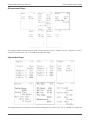
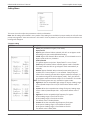
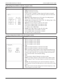
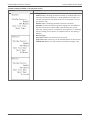
P90L 6kVA & 10kVA Online UPS
6kVA, 10kVA Models
User & Installation Manual
www.xpcc.com | © 2014 Xtreme Power Conversion Corporation. All rights reserved. (Rev 10/09/14)
P90L 6kVA & 10kVA User’s Manual
Uninterruptible Power Supply
Please comply with all warnings and operating instructions in this manual.
Save this manual and read the following instructions carefully before installing the unit. Do not operate this unit before reading all safety information
and operating instructions carefully.
Xtreme Power Conversion Corporation
Page 2
P90L 6kVA & 10kVA User’s Manual
Uninterruptible Power Supply
Table of Contents
Safety Warnings and EMC Instructions.........................................................5
UPS Warnings..................................................................................................................................5
Maintenance Warnings....................................................................................................................5
Battery Warnings.............................................................................................................................5
Standards.........................................................................................................................................6
Installation...................................................................................................7
UPS Unpacking and Inspection........................................................................................................7
Rear Panel View...............................................................................................................................7
System Single Line Diagram...........................................................................................................10
Rack/Tower Installation.................................................................................................................10
UPS Electrical Installation..............................................................................................................11
Operations.................................................................................................13
Operating Mode/Status Description..............................................................................................13
Button Operation...........................................................................................................................13
LED Indicators................................................................................................................................14
Audible Alarm................................................................................................................................14
UPS Operation...............................................................................................................................14
LCD Operation...............................................................................................................................17
Main Interface (Home Screen).......................................................................................................18
Operation Menu............................................................................................................................18
Control Items.................................................................................................................................19
Measurement Pages......................................................................................................................21
Information Pages..........................................................................................................................21
Setting Menu.................................................................................................................................22
Alarm Page....................................................................................................................................25
Troubleshooting.........................................................................................26
Warning Status..............................................................................................................................26
Fault Mode....................................................................................................................................26
Xtreme Power Conversion Corporation
Page 3
P90L 6kVA & 10kVA User’s Manual
Uninterruptible Power Supply
Trouble Shooting Table..................................................................................................................26
Storage.......................................................................................................29
Specifications.............................................................................................30
Obtaining Service.......................................................................................31
Xtreme Power Conversion Limited Warranty...............................................32
Xtreme Power Conversion Load Protection Policy.......................................33
Appendix A: P90L-BP240 User Guide..........................................................36
Important Safety Warnings............................................................................................................36
Installation and Setup....................................................................................................................36
Storage & Maintenance.................................................................................................................38
Appendix B: P90L-RAIL Installation Guide...................................................39
Package Contents...........................................................................................................................39
Assembly Steps..............................................................................................................................39
Appendix C: P90L-ISO6MB & P90L-ISO10MB User Guide.............................42
Important Safety Instructions........................................................................................................42
Rear Panel Explanation..................................................................................................................43
Installation And Operation.............................................................................................................44
Terminal Block Explanations for Input, Output..............................................................................47
Troubleshooting.............................................................................................................................49
Specifications.................................................................................................................................49
Xtreme Power Conversion Corporation
Page 4
P90L 6kVA & 10kVA User’s Manual
Uninterruptible Power Supply
Safety Warnings and EMC Instructions
This manual contains important instructions that you should follow during installation and maintenance of the
UPS and batteries. Please read all instructions before operating the equipment and save this manual for future
reference.
UPS Warnings
• Install your UPS indoors, away from excess moisture or heat, direct sunlight, dust and conductive contaminants.
• Install your UPS in a structurally sound area. Your UPS is extremely heavy; take care when moving and lifting the unit.
• Only operate your UPS at indoor temperatures between 32°F and 104°F (between 0°C and 40°C).
• Leave adequate space around all sides of the UPS for proper ventilation.
• Do not install the UPS near magnetic storage media, as this may result in data corruption.
• Do not mount unit with its front or rear panel facing down (at any angle). Mounting in this manner will seriously inhibit the unit’s internal cooling, eventually causing product damage not covered under warranty.
• This UPS should be connected with a grounded system. NEC and local electrical codes apply.
• The power supply for this unit must be single-phase rated in accordance with the equipment nameplate.
It also must be suitably grounded
• Use of this equipment in life support applications where failure of this equipment can reasonably be expected to cause the failure of the life support equipment or to significantly affect its safety or effectiveness
is not recommended. Do not use this equipment in the presence of a flammable anesthetic mixture with
air, oxygen or nitrous oxide.
• Connect your UPS power module’s grounding terminal to a grounding electrode conductor.
• The UPS is connected to a DC energy source (battery). The output terminals may be live when the UPS is
not connected to an AC supply.
Maintenance Warnings
• Service and repair should be done only by trained personnel. During any service work to the UPS, it should
be turned off or manually bypassed. Note that potentially lethal voltages exist within this unit as long as
the battery supply is connected.
• Your UPS power module and battery module(s) do not require routine maintenance. Do not open them for
any reason. There are no user-serviceable parts inside.
• Even after the unit is disconnected from the mains, components inside the UPS system are still connected
to the battery packs which are potentially dangerous.
• Before carrying out any kind of service and/or maintenance, disconnect the batteries and verify that no
current is present and no hazardous voltage exists on PCB components
• Fuses should be replaced only by factory authorized personnel. Blown fuses should be replaced only with
fuses of the same rating and type.
• Verify that no voltage between the battery terminals and the ground is present before maintenance or
repair. In this product, the battery circuit is not isolated from the input voltage. Hazardous voltages may
occur between the battery terminals and the ground.
Battery Warnings
• Do not operate your UPS without connecting it to an external battery module.
• Batteries can present a risk of electrical shock and burn from high short-circuit current. Observe proper
Xtreme Power Conversion Corporation
Page 5
P90L 6kVA & 10kVA User’s Manual
•
•
•
•
•
•
Uninterruptible Power Supply
precautions.
a) Remove watches, rings, and other metal objects
b) Use tools with insulated handles.
c) Wear rubber gloves and boots.
d) Do not lay tools or metal parts on top of batteries.
e) Disconnect charging source prior to connecting or disconnecting battery terminals.
Do not dispose of the batteries in a fire. Do not open the batteries. The batteries must be disposed of in
accordance with local regulations.
Do not short or bridge the battery terminals with any object.
Unplug and turn off the UPS before performing battery replacement.
Battery replacement should be performed only by authorized service personnel using the same number
and type of batteries (Sealed Lead-Acid). Use tools with insulated handles. The batteries are recyclable.
Do not open or mutilate the batteries. Released electrolyte is harmful to the skin and eyes, and may be
toxic.
Do not connect or disconnect battery module(s) while the UPS is operating from the battery supply.
Standards
* Safety
Safety Conformance: IEC/EN 62040-1,UL1778 (4th Edition)
Safety Markings : TUV, cTUVus, CE, UL, cUL, RoHS
* EMI
Conducted Emission...............................:IEC/EN 62040-2
Radiated Emission..................................:IEC/EN 62040-2
*EMS
ESD.........................................................:IEC/EN 61000-4-2
RS........................................................ ...:IEC/EN 61000-4-3
EFT......................................................... :IEC/EN 61000-4-4
SURGE................................................... :IEC/EN 61000-4-5
CS........................................................... :IEC/EN 61000-4-6
Power-frequency Magnetic field.............. :IEC/EN 61000-4-8
Low Frequency Signals............................:IEC/EN 61000-2-2
Xtreme Power Conversion Corporation
Category C3
Category C3
Level 4
Level 3
Level 4
Level 4
Level 3
Level 4
Page 6
P90L 6kVA & 10kVA User’s Manual
Uninterruptible Power Supply
Installation
UPS Unpacking and Inspection
Open the package and check the contents. The shipping package contains:
• One UPS
• One user manual
• One 3ft, L6-30R output cord (P90L-6K only)
• One 6ft, L6-30P input cord (P90L-6K only)
• One monitoring software CD
• One USB cable
• Two sets of tower stands including feet and extensions
• Two Rack-mounting ears
Note: Before installation, please inspect the unit. Be sure that nothing inside the package has been damaged during transportation. Do not turn on the unit and notify the carrier and dealer immediately if there is any damage or
missing parts. Please keep the original packing material in a safe place for future use.
Rear Panel View
P90L-10K Rear Panel
P90L-6K ships with default cord kit
P90L-6K and 10K Input/Output Terminal
Xtreme Power Conversion Corporation
Page 7
P90L 6kVA & 10kVA User’s Manual
Uninterruptible Power Supply
P90-BP240 Battery Pack Rear Panel
Connection between P90-BP240 and P90L UPS
Xtreme Power Conversion Corporation
Page 8
P90L 6kVA & 10kVA User’s Manual
Uninterruptible Power Supply
1. RS-232 communication port
2. USB communication port
3. EPO (Emergency Power Off) connector
4. Share current port (parallel systems only)
5. Parallel port (for future use)
6. Intelligent slot
7. EMBS (External Maintain Bypass Switch) port
8. Cooling fan
9. External battery connector
10. Input circuit breaker
11. Input/output terminal - P90L-6K ships with default cord kit
12. Input terminal
13. Ground
14. Output terminal
15. Battery pack output circuit breaker
Note: EPO connector is normally closed (NC) for normal operation. To activate EPO function, remove the NC signal.
Normally Closed EPO
WARNING: The EPO, RS-232 and USB circuits are IEC 60950 safety extra low voltage (SELV) circuits. This
circuit must be separated from any hazardous voltage circuits by reinforced insulation.
Xtreme Power Conversion Corporation
Page 9
P90L 6kVA & 10kVA User’s Manual
Uninterruptible Power Supply
System Single Line Diagram
System single line diagram is shown below:
Rack/Tower Installation
Tower Installation
The UPS system is shipped with four plastic feet and 6 plastic extensions (2 short extensions plus 4 long extensions). These are to be used to install the P90L UPS or UPS and BP240 battery module in tower configuration:
1. For UPS only, assemble two feet and one short extension together as front support. Assemble rear support
in the same manner.
2. For UPS and Battery Module, assemble two feet and two long extensions together as front support. Assemble rear support in the same manner.
3. Align the two supports in your installation area, appropriately 14 inches apart.
4. Then, simply put the UPS module and battery module in the stands as shown in step 3. Be sure that the
UPS LCD display is on the upper half part of front panel.
Step 1
Step 2
Step 3
14 in
UPS only
Xtreme Power Conversion Corporation
Page 10
P90L 6kVA & 10kVA User’s Manual
Step 1
Uninterruptible Power Supply
Step 2
Step 3
14 in
UPS and Battery Module
Rack Installation
1. Attach mounting ears to the side mounting holes of UPS using the screws provided with the ears facing
forward.
2. Lift the UPS module and slide it onto the mounting rail kits. Attach the UPS module to the rack with the
screws, nuts and washers (user-provided) through its mounting ears and into the rack rails.
3. See Appendix B: P90L-RAIL Installation Guide for further details.
Step 1
Step 2
UPS Electrical Installation
Installation and wiring must be performed in accordance with local and national code/regulations.
1. Make sure the mains wire and breakers in the building are rated for the correct capacity of UPS.
2. Switch off the main feed before installation.
3. Turn off all the connected devices before connecting to the UPS.
4. Prepare wires based on the following table:
Model
P90L-6K
P90L-10K
Input
8
6
Wiring Spec (AWG)
Output
Battery
8
10
6
8
Ground
8
6
Note 1: P90L-6K input and output cords must be removed prior to proceeding with hardwire installation if required
Note 2: The wiring for P90L-6K should be able to withstand over 40A current. It is recommended to use 8AWG.
Note 3: The wiring for P90L-10K should be able to withstand over 63A current. It is recommended to use 6AWG or
Xtreme Power Conversion Corporation
Page 11
P90L 6kVA & 10kVA User’s Manual
Uninterruptible Power Supply
thicker wire for safety and efficiency.
Note 4: The selections for color of wires should be followed by the local electrical laws and regulations.
Note 5: External battery wires must use reinforced insulation or double insulated wire.
Warning:
• For standard P90-BP240 battery module, there is one DC breaker to disconnect the battery bank and the
UPS. For nonstandard external battery options, make sure a DC breaker or other protection device between UPS and external battery module is installed.
Note: Set the battery module breaker in “OFF” position and then install the battery module.
• Pay attention to the polarity marking on external battery connector and make sure the battery polarity is
correct. Wrong connection may cause permanent damage of the UPS.
• Make sure the protective earth ground wiring is correct. The wire current spec, color, position, connection
and conductance reliability should be checked carefully.
• Make sure the utility input & output wiring is correct. The wire current spec, color, position, connection
and conductance reliability should be checked carefully. Make sure the N (or L2) site is correct.
Xtreme Power Conversion Corporation
Page 12
P90L 6kVA & 10kVA User’s Manual
Uninterruptible Power Supply
Operations
Operating Mode/Status Description
Mode/Status
UPS power on
Line Mode
Battery Mode
Bypass Mode
ECO Mode
Frequency Converter
Mode
Battery Test Mode
Warning Status
Fault Mode
Description
When UPS is powered on, it will enter into this mode for a few seconds for initializing
the CPU and system.
When the input voltage is within acceptable range, and the UPS is turned on (the inverter is running), the UPS will provide pure and stable sine wave AC voltage. The UPS
will also charge the battery in Line mode.
When the input voltage is out of the acceptable range or a power failure occurs, and
the UPS is turned on (the inverter is running), the UPS will backup power from battery.
When input voltage is within acceptable range and bypass is enabled, and the UPS
(inverter) is not turned on or the inverter can’t support the load, the UPS will switch
to battery.
When the input voltage is within voltage regulation range and “ECO” mode is enabled,
the UPS will bypass voltage to output for energy saving. If the input voltage is out of
the regulation range but it is still within acceptable range of Line mode, the UPS will
transfer to inverter supplying the power to load (similar to Line mode).
When input frequency is within 46 to 64Hz, the UPS can be set with a constant output
frequency (50 Hz or 60 Hz) through the inverter. The UPS will still charge the battery in
this mode. Bypass is disabled in this mode.
When the UPS is in Line mode or Converter mode, and the battery test command is
enabled through LCD or monitoring software, the UPS will start Battery Test. This operation is used to check the battery status.
If some errors occur in the UPS (but it is still running normally), buzzer will alarm and
warning code will appear in the LCD for trouble shooting.
When fatal error occurs in the UPS, it will beep continuously and go to fault mode. It
will display fault codes in LCD.
Button Operation
Buttons
LCD Panel
LED indicators
Xtreme Power Conversion Corporation
Page 13
P90L 6kVA & 10kVA User’s Manual
Uninterruptible Power Supply
There are 4 buttons on front panel.
Button
ON/ENTER
OFF/ESC
UP*
DOWN*
Function
•
•
•
•
•
•
•
•
•
•
Press this button to turn on the UPS.
Or press it to confirm the selection in the menu.
Press this button to turn off the UPS.
Or press it to return to last menu.
Press this button to select the previous item in the menu.
Or press this button to jump to previous page in the screen.
Or press this button to increase the number in the setting.
Press this button to select the next item in the menu.
Or press this button to jump to next page in the screen.
Or press this button to decrease the number in the setting.
*If pressing UP and DOWN button together, the LCD display will rotate 90° automatically. This operation is used
when configuring the UPS to Rack or Tower display.
LED Indicators
There are 4 LEDs on front panel to show the UPS working status:
Mode
Bypass
Line
UPS power on
●
●
Bypass mode
●
○
Line mode / Converter mode
○
●
Battery mode
○
○
Fault mode
○
○
Battery test mode
○
●
ECO mode
●
●
Note: ● means LED is lit; ○ means LED is off; ● means LED is flashing.
Battery
●
○
○
●
○
●
○
Fault
●
○
○
○
●
○
○
Audible Alarm
UPS status
Bypass mode
Battery / Battery-test mode (normal battery voltage)
Battery / Battery-test mode (low battery voltage)
Fault
Warnings (except overload)
Overload
Other
Buzzer status
Beeping once every 2 minutes
Beeping once every 4 seconds
Beeping once every second
Beeping continuously
Beeping once every second
Beeping twice every second
Mute
UPS Operation
Turn on the UPS with utility power supply (to Line mode)
1. Make sure mains input and battery are connected , and the battery pack breaker is in the
“ON” position; Set the external mains input breaker to “ON” position, then the fan will be runXtreme Power Conversion Corporation
Page 14
P90L 6kVA & 10kVA User’s Manual
Uninterruptible Power Supply
ning and the UPS supplies power to the loads via bypass; (The UPS is operating in Bypass mode.)
Note: When UPS is in Bypass mode, the output voltage comes directly from utility, so the load is not protected by the UPS. To protect the load, the UPS should be turned on to Line mode.
2. When LCD is on home screen, press the “ON/ENTER” button, LCD will show a prompt page of “Turn On”;
Move the arrow to “Yes” by up or down button, then press “ON/ENTER”, the UPS will beep once and start
UPS. You could also enter the “control menu” to select the instruction “Turn On” to startup the UPS. Please
refer to the section of “LCD operation”.
3. A few seconds later, the UPS will enter into Line mode; “Line mode” will be displayed on LCD. (In line
mode, if the utility power is abnormal, the UPS will transfer to Battery mode without interruption.)
Turn on the UPS without utility power supply (to Battery mode)
1. Make sure the battery is connected and the battery pack breaker is in the “ON” position;
2. Press the “ON/ENTER” button to start up the internal power, the UPS will enter into bypass mode without
output;
3. When LCD is on home page, press the “ON/ENTER” button, LCD will show a prompt page of “Turn On”;
Move the arrow to “Yes” by up or down button, then press “ON/ENTER”, the UPS will beep once and start
up. You could also enter the “control menu” to select the instruction “Turn On” to startup the UPS. Please
refer to the section of “LCD operation”.
4. A few seconds later, the UPS will enter into Battery mode; “Battery mode” will be displayed on LCD (In
Battery mode, it will shutdown automatically when battery is depleted. If the utility power is restored, it
will auto restart to Line mode.)
Connect devices to UPS
After the UPS is turned on, you can add load to the UPS.
1. Turn on the UPS first and then switch on the load devices one by one, the LCD panel will display total load
level.
2. If inductive loads, such as a printer, are connected, the in-rush current should be calculated carefully to
see if the capacity of the UPS is sufficient due to the huge starting power consumption of this kind of load.
3. If the UPS is overloaded, the buzzer will beep twice every second.
4. When the UPS is overloaded, please remove some loads immediately. It is recommended to have the total
load connected to the UPS be less than 80% of its nominal power capacity for system safety.
5. If the overload time exceeds duration listed in the spec at Line mode, the UPS will automatically transfer to
bypass mode. After the overload is removed, it will return to Line mode. If the overload time exceeds duration listed in spec at Battery mode, the UPS will enter fault status. At this time, if bypass is enabled, the
UPS will power the load via bypass. If bypass function is disabled or the input power is not within bypass
acceptable range, it will cut off the output immediately.
Charge the batteries
1. After the UPS is connected to the utility power, the charger will charge the batteries automatically except
in Battery mode or during battery test;
2. Suggest charging batteries at least 4 hours before use. Otherwise, the backup time may be shorter than
expected;
3. Make sure the battery numbers setting on the control board (Please refer to the section of changing battery quantity) is consistent with actual connection.
Battery mode operation
1. When the UPS is in Battery mode, the buzzer will beep according to the battery capacity. Normally, the
buzzer will beep once every 4 seconds in battery mode, but when the battery voltage drops to the alarm
level, the buzzer will beep once per second and the UPS will shut down automatically when the battery
reaches cutoff level. Users could switch off some non-critical loads to delay the shutdown alarm and prolong the backup time. If there is no more load to be taken off at that time, you must shut down all loads as
soon as possible to protect the devices or save data. Otherwise, there is a risk of data loss or load failure.
Xtreme Power Conversion Corporation
Page 15
P90L 6kVA & 10kVA User’s Manual
Uninterruptible Power Supply
2. In Battery mode, you can mute the alarm by entering ”Control->Mute” on LCD to silence it. Please refer
to the section of “LCD operation”.
3. The backup time depends on the external battery capacity.
4. The backup time may change under different environment temperature and load type.
5. The maximum backup time is limited by default to 16.5 hours (After discharging 16.5 hours, UPS will shut
down automatically to protect the battery). The time could be modified through LCD panel or communication port.
Test the batteries
1. If you need to check the battery status or performance when the UPS is running in Line / Converter / ECO
mode, you could enter ”Control->Batt Test” to instruct the UPS to perform a battery test. Please refer to
the section of “LCD Operation”.
2. Users also can set battery test through monitoring software.
3. If the UPS is in battery testing, “Battery test mode” will be displayed on LCD, the buzzer indication will be
the same as Battery mode, but both line LED and battery LED will be lit.
Turn off the UPS with utility power supply in Line mode
1. When LCD is on home page, press the “OFF/ESC” button, LCD will show a prompt page of “Turn Off”; Move the arrow to “Yes” by up or down button, then press “ON/ENTER”, the UPS will beep
once and turn off. Power is still applied via bypass mode. You could also enter the “control menu” to
select the instruction “Turn Off” to turn off the UPS. Please refer to the section of “LCD operation”.
Note: Here, “Turn Off” means that UPS is not working on line / converter / ECO / battery / battery test
mode. So even though the UPS is turned off, if input or bypass voltage is normal, the internal power supply will still be working; and if bypass status has been set to “enable”, the output voltage of the UPS will
still exist.
2. If you need to fully cut off the output, switch off the external input breaker. A few seconds later, there is
no display shown on the panel and UPS is completely off.
Turn off the UPS without utility power supply in Battery mode
1. When LCD is on home page, press the “OFF/ESC” button, LCD will show a prompt page of “Turn Off”; Move
the arrow to “Yes” by up or down button, then press “ON/ENTER”, the UPS will beep once and turn off.
Power is still applied via bypass mode. You could also enter the “control menu” to select the instruction
“Turn Off” to turn off the UPS. Please refer to the section of “LCD operation”.
2. If there is no bypass input voltage, the UPS will cut off all power supply and there is no display shown on
the panel.
Xtreme Power Conversion Corporation
Page 16
P90L 6kVA & 10kVA User’s Manual
Uninterruptible Power Supply
LCD Operation
The entire LCD structure is demonstrated in diagram below:
Xtreme Power Conversion Corporation
Page 17
P90L 6kVA & 10kVA User’s Manual
Uninterruptible Power Supply
Main Interface (Home Screen)
1.
2.
3.
4.
5.
In the first line, it will display the current mode the UPS is in.
When an alarm occurs, the warning or fault information will display below the “load” line;
When the front panel is not operated for quite a long time, the page will default back to this home page;
Press the “UP” or “DOWN” button to enter the main operation menu.
When LCD is on this home page, if UPS is in bypass, you could press the “ON/ENTER” button to turn on the
UPS to line / converter / ECO / battery mode according to the setting and input status; in reverse, you could
press the “OFF/ESC” button to turn off the UPS to bypass mode or shutdown. As previously mentioned in
“UPS Operation” section of this manual.
Operation Menu
Main menu
1. After pressing the “UP” or “DOWN” button at the home page, the screen will display the main menu of
the operation menu. In the main menu, there are 5 items (Control / Measurement / Information / Setting
/ Alarm) to select.
2. Press “UP” or “DOWN” button to select item.
3. Press “ON/ENTER” button to confirm the selection.
4. Press “OFF/ESC” button to go back to the home page;
5. This operation is the same or similar in other menus or pages. Please refer to the section of “Button Operation” section.
Xtreme Power Conversion Corporation
Page 18
P90L 6kVA & 10kVA User’s Manual
Uninterruptible Power Supply
Control Items
Note: “Turn On” will be displayed if UPS is not turned on. “Turn Off” will be displayed if UPS is turned on. In general
situations, these items will not be displayed at the same time or in all operation modes.
1. Turn On/Turn Off
This item is for turning on/off the UPS;
a. In Bypass mode, it will display “Turn On”, if it is selected and confirmed, the UPS will transfer to line mode,
converter mode, ECO mode, or battery mode according to the settings and input status.
→
→
Note: You could turn on the UPS by pressing “ON/ENTER” button at the home page. It’s not necessary to
enter into this control menu to turn on the UPS.
b. On line mode or converter mode or ECO mode or battery mode, it will display “Turn Off” in control menu.
If it is selected and confirmed, the UPS will transfer to bypass mode or shut down.
→
→
Note: You could turn off the UPS by pressing “OFF/ESC” button at the home page. It is not necessary to
enter into this control menu to turn off the UPS.
2. Battery Test
Battery test is used to ensure that the UPS could work well in battery mode and to test the battery performance.
This item could be shown in all modes but will not work in Battery/Fault/Eco mode. Related data will be shown at
the same time.
Xtreme Power Conversion Corporation
Page 19
P90L 6kVA & 10kVA User’s Manual
Uninterruptible Power Supply
→
→
3. Mute
This item is used to mute the buzzer in battery/bypass/fault mode. In any other mode, this item also could be seen
but does not function and related data will also be shown. After confirmation, it will go to the home page and you
can see the change of the mute icon.
→
→
4. Para Unlock (Future Use)
This selection is for “parallel (protection) unlock”, to allow for parallel unit operation. It only appears when the LCD
shows the warning “3F: Para Protect” (that means the parallel system is in protection and cannot startup); if you
need to startup the parallel UPS, this instruction must be executed.
Note: Before executing this instruction, you must check that the system’s parallel cables and connections are correct. Please read the related content in the trouble shooting section of this manual.
→
Xtreme Power Conversion Corporation
→
Page 20
P90L 6kVA & 10kVA User’s Manual
Uninterruptible Power Supply
Measurement Pages
These pages display the measurement value of the parameters such as voltage / current / frequency / power /
capacity / time etc. Press “UP” or “DOWN” to navigate the pages.
Information Pages
These pages display the information of parameters setting value or status. Press “UP” or “DOWN” to navigate the
Xtreme Power Conversion Corporation
Page 21
P90L 6kVA & 10kVA User’s Manual
Uninterruptible Power Supply
Setting Menu
This menu is used to adjust the parameters or do the calibrations.
Note: Not all settings are available in every mode. If the setting is not available in present mode, the LCD will show
prompt message with “Item cannot be set in this mode”. Press any button or just wait for several seconds then this
message will disappear.
1) Bypass setting
Interface
Xtreme Power Conversion Corporation
Description
1. Status (only available in bypass / line mode)
Open/Forbid:
Open: Bypass allowed. When selected, UPS will run at Bypass mode
depending on bypass enabled/disabled setting.
Forbid: Bypass not allowed. When selected, it’s not allowed to run in
Bypass mode under any situations.
Enable/Disable
This option appears only when “Open/Forbid” is set to “Open”.
Enable: Bypass enabled. When selected, Bypass mode is available.
This means that the UPS can go to Bypass mode automatically or
manually.
Disable: Bypass disabled. When selected, automatic bypass is acceptable, but “manual bypass” is not available. “Manual bypass”
means users manually operate UPS to Bypass mode (for example, in
Line mode turning off the UPS to Bypass mode). Then, the UPS will
go to bypass mode but without output if it is turned off in line mode.
NOTE: The following items are only available in bypass mode.
2. HighLoss V: Set the acceptable high voltage for bypass. Setting range
is from (Rated Output Volt +11V) to 276V and the default value is
264V.
3. LowLoss V: Set the acceptable low voltage for bypass. Setting range
is from 110V to (Rated Output Volt - 11V) and the default value is
110V.
4. HighLoss F: Set the acceptable high frequency for bypass.
50 Hz: Setting range is from 51Hz to 54 Hz.
60 Hz: Setting range is from 61Hz to 64Hz.
The default value is 54.0Hz/64.0Hz.
5. LowLoss F: Set the acceptable high frequency for bypass.
50 Hz system: Setting range is from 46.0Hz to 49.0Hz.
60 Hz system: Setting range is from 56.0Hz to 59.0Hz.
The default value is 46Hz/56Hz.
Page 22
P90L 6kVA & 10kVA User’s Manual
Uninterruptible Power Supply
2) ECO setting (only available or effective on bypass mode)
Interface
Description
1. Status
Enable: Enable ECO Function
Disable: Disable ECO Function
If ECO function is disabled, voltage range and frequency range for
ECO mode can still be set, but it is meaningless unless the ECO function is enabled.
2. HighLoss V: High voltage point in ECO mode. The setting range is
from +5% to +10% of the nominal voltage.
3. LowLoss V: Low voltage point in ECO mode. The setting range is from
-5% to -10% of the nominal voltage.
4. HighLoss F: Set low frequency point for ECO mode.
50 Hz system: Setting range is from 46Hz to 48Hz.
60 Hz system: Setting range is from 56Hz to 58Hz.
The default value is 48Hz/58Hz.
5. LowLoss F: Set high frequency point for ECO mode.
50 Hz: Setting range is from 52.0Hz to 54.0 Hz.
60 Hz: Setting range is from 62.0Hz to 64.0Hz.
The default value is 52.0Hz/62.0Hz.
3) Output setting (only available or effective on bypass mode)
Interface
Xtreme Power Conversion Corporation
Description
1. Volt:
208: The voltage is set for 208VAC
220: The voltage is set for 220VAC
230: The voltage is set for 230VAC
240: The voltage is set for 240VAC
2. Freq:
50Hz: The output frequency is manual set for 50Hz.
60Hz: The output frequency is manual set for 60Hz.
ATO: If selected, output frequency will be decided according to the
latest normal utility frequency. If it is from 46Hz to 54Hz, the output
frequency will be 50.0Hz. If it is from 56Hz to 64Hz, the output frequency will be 60.0Hz. ATO is default setting.
3. CVCF:
Used to enable or disable frequency converter mode.
Enable: The output frequency will be fixed at 50Hz or 60Hz according to setting of “Freq”. The input frequency could be from 46Hz to
64Hz.
Disable: The output frequency will synchronize with the input frequency within 46~54 Hz for 50Hz system or within 56~64 Hz for 60Hz
system.
Note: CVCF means Constant Voltage and Constant Frequency, it represents frequnecy converter mode.
Page 23
P90L 6kVA & 10kVA User’s Manual
Uninterruptible Power Supply
4) Battery setting (available on all operation modes)
Interface
Xtreme Power Conversion Corporation
Description
1. Dischg Protect:
Enable: Battery discharge protection function is enabled. When UPS
has been continuously working in “battery/battery test mode”, the
UPS will automatically shut down when the running time set by option below is met;
Disable: Battery discharge protection function is disabled.
000~999: The maximum discharge time ranging from 0 to 999mins.
UPS will shut down to protect battery after backup time arrives
when the “Dischg Protect” is enabled. If “Dischg protect” is disabled,
then this setting is not relevant; The default value for this setting is
990mins.
2. Batt Test Type:
Short Time: Battery test will last for 10 seconds;
Long Time: Battery test time, can be adjusted within 01~99 minutes.
Till Batt Low: Battery test will continue until battery voltage is low.
Page 24
P90L 6kVA & 10kVA User’s Manual
Uninterruptible Power Supply
5) Calibration
Interface
Description
The Batt, Inv, and Chg calibrations can be adjusted to ensure the front
panel display value matches the actual voltages measured in the UPS
with a multimeter.
1. Batt: Calibrate the battery voltage measurement; the calibration
range is from 0V to 5.7V, the default value is 0V. It is available on all
operation modes.
2. Inv: Adjust the inverter output voltage; the adjustable range is from
0V to 6.4V, the default value is 0V. It is only available in line / battery
/ converter mode;
3. Chg: Adjust the Charger output voltage; the adjustable value is from
0V to 6.9V, the default value is 0V. It is only available in bypass / line
/ ECO /converter mode.
(Note: Before making charger output voltage adjustment, be sure to
disconnect all batteries first to get the accurate charger voltage; Be
careful that the adjustment should be suitable to battery specifications, or the battery may be destroyed.)
Alarm Page
This page records and displays the faults or warnings event history.
Xtreme Power Conversion Corporation
Page 25
P90L 6kVA & 10kVA User’s Manual
Uninterruptible Power Supply
Troubleshooting
Warning Status
When Fault LED flashes and the buzzer beeps once every second, it means that the UPS has experienced a warning
condition. Users can see the warning code on the LCD panel and refer to the trouble shooting table to check the
warning condition.
Fault Mode
1. When Fault LED illuminates and the buzzer beeps continuously, it means that there is a fatal error with the
UPS. Users can get the fault code from LCD panel. Please refer to the trouble shooting table to check the
fault condition.
2. Don’t try to turn on the UPS again until the fault is cleared. If the fault can’t be fixed, please contact the
manufacturer immediately.
3. In case of an emergency, please cut off the connection from utility, external battery, and output immediately to avoid more risk or danger.
Trouble Shooting Table
If the UPS system does not operate correctly, please solve the problem by referring to the table below:
Alarm type LCD display
Possible cause
• The battery connection is loose;
• The battery protection device is
open.
• Battery numbers and its setting is
not matching;
• Charger voltage is too high, the
charger failed.
• Battery is discharged deeply to
low voltage;
• Battery number is not correct;
• Battery is at the end of life.
Warning
01: Batt Open
Warning
07: Over
Charge
Warning
08: Batt Low
Warning
09: Over load
• The load is too heavy.
Warning
0A: Fan Error
• Fan is blocked;
• Fan is in the end of life;
• Fan detection circuit failed.
Warning
0B: EPO Enable
• EPO plug (jumper) is removed or
the external EPO switch is off.
Xtreme Power Conversion Corporation
Remedy
• Tighten the battery connection;
• Replace or restore the protection
device.
• Disconnect the battery and check
the charger output voltage, contact the dealer for repair.
• Recharge the battery;
• Correct the battery number;
• Replace the battery.
• Remove excess loads from UPS
output.
• Unblock the fan;
• Contact the dealer for replacing
the fan;
• Contact the dealer for repair.
• Connect the EPO plug (jumper) or
switch on the external EPO switch.
Page 26
P90L 6kVA & 10kVA User’s Manual
Warning
Warning
Warning
Warning
Warning
Warning
Fault
Fault
Fault
• The internal temperature is too
high and has reached the warning
level:
• Environment is too hot;
0D: Over Temp
• Fan is blocked or failed;
• UPS ventilation points are blocked
by the wall or other goods;
• Load is too heavy.
0E: Charger Fail • Charger failed.
10: IP Fuse
• Input fuse on the power board is
Open
open.
33: Overload 3
Times
• Locked in bypass after overload 3
times in 30 minutes.
Uninterruptible Power Supply
• Make sure the ambient temperature is not over 40°C;
• Make sure the fan is OK;
• Make sure the ventilation points
are clear;
• Reduce the load.
• Contact the dealer for repair.
• Check and replace the input fuse.
• Remove excess loads from UPS
output first, then shut down the
UPS and restart it.
• External Maintenance Bypass
Switch (EMBS) port is open or the
3A: Maintain
• If the EMBS port is short-circuited,
maintain switch sensor (connected
Open
the warning will disappear.
to EMBS port) is triggered. (The
UPS is transferred to bypass).
• If the system still needs to be operated in parallel mode, please connect the parallel cable, and choose
“Para Unlock” in control menu to
remove the warning, then the UPS
can start up.
• Parallel cable is still not connected • If the UPS in the system are sepawhen restart after the parallel
rated to single UPS, please disconsystem is faulty because of parallel
nect the output to other UPS and
3F: Para Protect
communication failure. (When this
choose “Para Unlock” in control
(Future Use)
warning appears, the UPS can not
menu to remove the warning, then
start up, it is protection for parallel
the UPS can start up.
system)
Note: Be careful to check the UPS
operation mode (parallel or single)
and the connections. If the parallel cable is not connected in the
parallel mode, the UPS may be
damaged.
• The internal converter failed, so
01: Bus Start
the DC bus voltage could not be
• Contact the dealer for repair
Fail
boosted correctly.
• The mains input or load transient
• Shutdown and restart the system
current caused the DC bus voltage
02: Bus Over
to see if the fault clears;
to be too high;
• Contact the dealer for repair.
• The internal converter failed.
• The internal converter failed, so
03: Bus Under
• Contact the dealer for repair.
the DC bus voltage is too low.
Xtreme Power Conversion Corporation
Page 27
P90L 6kVA & 10kVA User’s Manual
Fault
Fault
Fault
Fault
Fault
Fault
Fault
Fault
Fault
Fault
Fault
Fault
Fault
• The load is abnormal, so the internal positive and negative DC bus
voltages are unbalanced;
• The internal converter failed.
• The internal inverter failed, so the
11: Inv Start Fail
inverter voltage could not start up
correctly.
12: Inv Volt
• The internal inverter failed, so the
High
inverter voltage is too high.
• The internal inverter failed, so the
13: Inv Volt Low
inverter voltage is too low.
14: Output
• Short circuit occured on the UPS
Short
output.
• UPS output power is negative. It
means there is energy feedback
into the UPS from output. It may
1A: NegPower
be caused by regenerative load;
or caused by the current control
failure in the parallel system.
21: Batt SCR
• The internal battery SCR has failed
Short
(shorted).
• The internal inverter relay is stuck
24: Inv Rly
in the shorted position or the SCR
Short
of STS (Static Transfer Switch) is
shorted.
• Parallel cable for communication
35: Para Comm
is not connected in the parallel
Fail
system.
• The output current is extremely
36: OP.I
unbalanced between the paralUnbalance
leled UPSs, there is an error in the
parallel system.
The internal temperature is too high
and has reached the fault level (shutdown):
• The environment is hot;
41: Over Temp
• The fan is blocked or failed;
• The ventilation is blocked by the
wall or other goods;
• Load is too heavy.
42: CPU Comm • Internal communication between
Fail
the CPUs failed
• Overload time is out of the speci43: Over load
fication and the UPS shut down
automatically.
04: Bus Unbalance
Xtreme Power Conversion Corporation
Uninterruptible Power Supply
• Contact the dealer.
• Contact the dealer for repair.
• Contact the dealer for repair.
• Contact the dealer for repair.
• Remove the short circuit.
• Contact the dealer.
• Contact the dealer for repair.
• Contact the dealer for repair.
• Connect the parallel cable.
• Contact the dealer for repair.
• Make sure the ambient temperature not over 40°C;
• Make sure the fan is OK;
• Make sure the ventilation is clean;
• Remove some loads.
• Contact the dealer for repair.
• Remove excess loads from UPS
output and restart it.
Page 28
P90L 6kVA & 10kVA User’s Manual
Uninterruptible Power Supply
Storage
Before storing, charge the UPS batteries for at least 7 hours. Store the UPS covered and upright in a cool, dry location. During storage, recharge the battery in accordance with the following table:
Storage Temperature
-25°C - 40°C
40°C - 45°C
Xtreme Power Conversion Corporation
Recharge Frequency
Every 3 months
Every 2 months
Charging Duration
1-2 hours
1-2 hours
Page 29
P90L 6kVA & 10kVA User’s Manual
Uninterruptible Power Supply
Specifications
P90L-6K
MODEL NUMBER
CAPACITY
INPUT
OUTPUT
AC output
Voltage
Frequency
Voltage
Frequency
THD (full load)
Overload capacity
Crest factor
Charger amps
BATTERY
CHARGER
Nominal/float voltage
UPS dimensions (W x D x H)
PHYSICAL
UPS weight
Input connection
Output connection
ENVIRONMENT Efficiency
Operating temperature
Audible noise
Altitude
Model number
OPTIONAL
BATTERY PACKS Dimensions (W x D x H)
Weight
Battery quantity/type
Dimensions (W x D x H)
OPTIONAL
TRANSFORMER Weight
APPROVALS
WARRANTY
COMMUNICATIONS INTERFACE
INCLUDED IN BOX
AVAILABLE OPTIONS
P90L-10K
6kVA (5.4kW)
10kVA (9kW)
110–300VAC*
50/60Hz
200/208/220/230/240VAC**
240/120VAC with optional isolation transformer with maintenance bypass
50/60Hz ± 4Hz
< 2%
110% 10 min; 130% 1 min; > 130% 1 sec
3:1
4A
240/270VDC
17.2 x 26.3 x 5.3 in
17.2 x 29.5 x 5.3 in
55 lbs
60 lbs
Terminal block with 6 ft, L6–30P
Terminal block
Terminal block with 3 ft, L6–30R
Terminal block
Up to 98% ECO mode and 92% online mode
32–104°F (0–40°C)
< 58dBA
< 60dBA
11,500 ft above sea level
P90L-BP240
17.3 x 25.1 x 5.3 in
165 lbs
(20) 12V9AH/240V
17.3 x 28.7 x 3.5 in
17.3 x 31.8 x 5.2
99 lbs
122 lbs
UL, cUL, RoHS
3 years electronics and battery (2 years outside of USA)
RS-232, USB, EPO, intelligent slot for optional cards
(Web/SNMP, Relay/dry contact, Modbus)
Software CD, horizontal brackets, tower pedestals
5 year extended warranty, power distribution (XPDU), 4-post rail kit,
2-post shelf kit, isolation transformer with maintenance bypass
*Depending on load level
**P90L capacity derates 10% at 200VAC output voltage
Frequency converter derates capacity 40%
Xtreme Power Conversion Corporation
Page 30
P90L 6kVA & 10kVA User’s Manual
Uninterruptible Power Supply
Obtaining Service
If the UPS requires Service:
1. Use the TROUBLESHOOTING section in this manual to eliminate obvious causes.
2. Verify there are no circuit breakers tripped.
3. Call your dealer for assistance. If you cannot reach your dealer, or if they cannot resolve the problem, call Xtreme
Power Conversion Corp Technical Support at 800.582.4524. Technical support inquiries can also be made at
[email protected]. Please have the following information available BEFORE calling the Technical Support
Department:
• Your name and address.
• The serial number of the unit.
• Where and when the unit was purchased.
• All of the model information about your UPS.
• Any information on the failure, including LED’s that may or may not be illuminated.
• A description of the protected equipment, including model numbers if possible.
• A technician will ask you for the above information and, if possible, help solve your problem over the
phone. In the event that the unit requires factory service, the technician will issue you a Return Material Authorization number (RMA).
If you are returning the UPS to Xtreme Power for service, please follow these procedures:
1. Pack the UPS in its original packaging. If the original packaging is no longer available, as the Technical Support Technician about obtaining a replacement set of packaging material. It is important to pack the UPS
properly in order to avoid damage in transit. Never use Styrofoam beads for a packing material.
2. Include a letter with your name, address, daytime phone number, RMA number, a copy of your original
sales receipt, and a brief description of the problem.
3. Mark the RMA number on the outside of all packages. Xtreme Power cannot accept any package without
the RMA number marked on the outside of the boxes.
4. Return the UPS by insured, prepaid carrier to the address provided by the Technician.
5. Refer to the Warranty statements in this manual for additional details on what is covered.
Xtreme Power Conversion Corporation
Page 31
P90L 6kVA & 10kVA User’s Manual
Uninterruptible Power Supply
Xtreme Power Conversion Limited Warranty
Xtreme Power Conversion (XPC) Corporation warrants Xtreme Power Conversion equipment, when properly applied and operated within specified conditions, against faulty materials or workmanship for a period of three years
for P90L-Series products from the date of purchase. XPC Corporation warrants P90L-Series battery packs for a
period of three years from the date of purchase. For equipment sites within the United States and Canada, this
warranty covers repair or replacement, at the sole discretion of XPC Corporation. The customer is responsible for
the costs of shipping the defective product to XPC Corporation. XPC Corporation will pay for ground shipment of
the repaired or replacement product. This warranty applies only to the original purchaser.
If equipment provided by XPC Corporation is found to be Dead-on-Arrival (DOA), XPC Corporation will be responsible for the costs of shipping product to and returning equipment from the customer in a timely manner as agreed
to with the customer, once the customer has requested and received a Return Material Authorization (RMA)
number. DOA equipment is defined as equipment that does not properly function according to user documentation when initially received and connected in conjunction with proper procedures as shown in the user documentation or via support provided by XPC Corporation personnel or authorized agents.
This warranty shall be void if (a) the equipment is repaired or modified by anyone other than XPC Corporation or
a XPC Corporation approved third party; (b) the equipment is damaged by the customer, is improperly used or
stored, is subjected to an adverse operating environment, or is operated outside the limits of its electrical specifications; or (c) the equipment has been used or stored in a manner contrary to the equipment’s operating manual,
intended use or other written instructions. Any technical advice furnished by XPC Corporation or a XPC Corporation authorized representative before or after delivery with regard to the use or application of Xtreme Power Conversion equipment is furnished on the basis that it represents XPC Corporations best judgment under the situation
and circumstances, but it is used at the recipient’s sole risk.
EXCEPT AS STATED ABOVE, XPC Corporation DISCLAIMS ALL WARRANTIES, EXPRESSED OR IMPLIED, INCLUDING
WARRANTIES OF MERCHANTABILITY AND FITNESS FOR A PARTICULAR PURPOSE.
EXCEPT AS STATED ABOVE, IN NO EVENT WILL XPC Corporation BE LIABLE FOR DIRECT, INDIRECT, SPECIAL, INCIDENTAL, OR CONSEQUENTIAL DAMAGES ARISING OUT OF THE USE OF Xtreme Power Conversion EQUIPMENT,
including but not limited to, any costs, lost profits or revenue, loss of equipment, loss of use of equipment, loss
of software, loss of data, cost of substitutes, or claims by third parties. Purchaser’s sole and exclusive remedy for
breach of any warranty, expressed or implied, concerning Xtreme Power Conversion equipment, and the only
obligation of XPC Corporation under this warranty, shall be the repair or replacement of defective equipment,
components, or parts; or, at XPC Corporations sole discretion, refund of the purchase price or substitution of an
equivalent replacement product. Xtreme Power Conversion Corporation
Page 32
P90L 6kVA & 10kVA User’s Manual
Uninterruptible Power Supply
Xtreme Power Conversion Load Protection Policy
THIS POLICY IS NOT A WARRANTY. REFER TO THE XPC CORPORATION, INC. LIMITED WARRANTY FOR
INFORMATION CONCERNING THE WARRANTY FOR YOUR XPC PRODUCT. THE LIMITATIONS AND CONDITIONS
CONTAINED IN THIS POLICY DO NOT AFFECT THE TERMS OF THE XPC LIMITED WARRANTY.
Definitions:
1. “Product” means a Standard 120, 208, or 240 Volt power protection device that is used in the United
States and Canada. This policy does not include custom manufactured products.
2. “Power Disturbance” means an AC power line transient (telephone line or Local Area Network, if applicable), spike or surge.
3. “Connected Equipment” properly connected electronic equipment
4. “Fair Market Value” of damaged Connected Equipment as determined by XPC shall be the lower of (a) the
average price the same or similar items are being sold for on eBay, (b) the price list of Orion Blue Book (or
if such price list is no longer published, a published or announced price list reasonably selected by XPC),
(c) the lowest price the same or similar items can be purchased for in the United States or (d) the total
amount of all payment(s) you have or are entitled to receive from insurance, other warranties, extended
warranties, a legal liability claim or from other sources or persons for the damaged Connected Equipment.
5. “Purchaser” means the person or entity that originally purchased the Product from an authorized reseller
or distributor of XPC Products.
The Purchaser of this Product is protected, for the term of the XPC Limited Warranty, against certain losses caused
by a Power Disturbance for properly connected electronic equipment (referred to as the "Connected Equipment")
subject to certain terms and conditions provided below.
This policy applies only to the original purchaser of the Product. If the Product is transferred or sold to another
person or entity, this policy is void.
Load Protection Policy Dollar and Period Limits
For purchasers that meet the qualifications and conditions set forth in this policy, XPC will provide reimbursement
(cost of repair or fair market value as determined by XPC) during the period limits and up to the dollar limits stated
as follows:
PRODUCT
XVT
XST
S70
XPRT 6kVA & 10kVA
NXRT
P90, P90L, P90g, P90Lg
T90
TX90, TX90i
DOLLAR LIMIT
25,000
25,000
25,000
50,000
50,000
50,000
50,000
50,000
PERIOD OF COVERAGE
Term of XPC Limited Warranty
Term of XPC Limited Warranty
Term of XPC Limited Warranty
Term of XPC Limited Warranty
Term of XPC Limited Warranty
Term of XPC Limited Warranty
Term of XPC Limited Warranty
Term of XPC Limited Warranty
This Load Protection Policy is not deemed "first dollar" coverage. XPC’s obligation is reduced by any amounts that
the Purchaser is entitled to recover, from other sources regarding the Connected Equipment, including, but not
limited to, insurance, other warranty, extended warranty, or legal liability, regardless of whether or not the Purchaser makes a claim for recovery.
Eligibility for Coverage Under the Load Protection Policy
1. The Product must be registered on the XPC website, www.xpcc.com, within 10 days of purchase. All required information must be provided, and Purchaser should retain a copy for Purchaser’s records. When
registering on the website, Purchaser must list all connected equipment that is directly connected to the
Xtreme Power Conversion Corporation
Page 33
P90L 6kVA & 10kVA User’s Manual
Uninterruptible Power Supply
product. Only those devices registered in that manner will be covered.
2. All Connected Equipment must be UL or CSA approved.
3. The Product must be plugged into a properly wired and grounded outlet. Use of input surge devices, extension cords, adapters, ground wires, or electrical connections not manufactured by XPC voids the XPC
Load Protection Policy. No other surge protection device may be connected to the output sockets of the
Product. The installation must comply with all applicable electrical and safety codes set forth pursuant to
the NEC.
4. The Product must have undeniable physical evidence of a Power Disturbance that directly and proximately
caused the damage;
5. The Connected Equipment must have been damaged by a Power Disturbance on a properly installed,
grounded, and National Electric Code, ("NEC"), code-compliant 120, 208, 240 Volt AC power line in the
United States or Canada, by a Power Disturbance on standard telephone land line or PBX telephone equipment line that is properly installed and connected to an RJ11 port on the Product; or by a Power Disturbance on a standard Local Area Network connection that is properly installed and connected to an RJ45
port on the Product and (d) is directly plugged into, and properly connected to, the Product in its original
condition which was properly operated when a Power Disturbance passed through the Product and (i)
exhausts the protection capacity of the Product or (ii) damages the Product.
6. The Load Protection Policy does not apply if the Product has been operated in a failure mode or not in
compliance with XPC operating instructions in the Product user's manual, or if the Connected Equipment
has not been operated in compliance with the instructions and manuals of its manufacturer/vendor.
7. This policy is null and void if, XPC determines, in its sole discretion, that the Product has been tampered
with or altered in any way.
What is Not Covered Under the Load Protection Policy:
The following damage is not covered by this Policy:
1. Restoration of lost data and reinstallation of software.
2. Damage from a cause other than AC power-line transients, except for damage due to telephone line, Local
Area Network, or CATV transients, which is covered only if the Product offers such protection.
3. DAMAGE CAUSED BY FAILURE TO PROVIDE A SUITABLE INSTALLATION ENVIRONMENT FOR THE PRODUCT
(INCLUDING, BUT NOT LIMITED TO, LACK OF A PROPER SAFETY GROUND).
4. Damage caused by the use of the Product for purposes other than those for which it was designed.
5. Damage caused by accidents, or natural disasters, including but not limited to, fire, flood, and wind.
6. Damage caused by abuse, misuse, alteration, modification, or negligence.
7. Any labor costs or travel, room and board expenses associated with the repair and/or restoration of lost or
damaged hardware, software or data.
EXCEPT AS EXPRESSLY PROVIDED IN THIS POLICY, XPC SHALL NOT BE LIABLE FOR ANY DAMAGES WHATSOEVER,
INCLUDING, BUT NOT LIMITED TO, DIRECT, INDIRECT, SPECIAL, INCIDENTAL, CONSEQUENTIAL, OR MULTIPLE
DAMAGES ARISING OUT OF THE USE OF THE PRODUCT OR DAMAGE TO THE CONNECTED EQUIPMENT, REGARDLESS OF THE LEGAL THEORY ON WHICH SUCH CLAIM IS BASED, EVEN IF ADVISED OF THE POSSIBILITY OF SUCH
DAMAGE. SUCH DAMAGES INCLUDE, BUT ARE NOT LIMITED TO, LOSS OF PROFITS, LOSS OF SAVINGS OR REVENUE, LOSS OF USE OF THE PRODUCT OR THE CONNECTED EQUIPMENT OR ANY ASSOCIATED EQUIPMENT, LOSS
OF SOFTWARE, COST OF CAPITAL, COST OF ANY SUBSTITUTE EQUIPMENT, FACILITIES OR SERVICES, DOWNTIME,
THE CLAIMS OF THIRD PARTIES, INCLUDING CUSTOMERS, AND INJURY TO PROPERTY.
Submitting a Load Protection Policy Claim:
1. Any claim under the Load Protection Policy must be made within 10 days of the date of alleged damage to the
Connected Equipment.
2. Call the XPC technical support department at 1-800- 582-4524 and obtain a Load Protection Policy Returned
Material Authorization (RMA) number. Have information on all applicable insurance or other resources of recovery/payment that is available to the Purchaser and the name of the power utility supplier for the location
of the Connected Equipment. XPC will forward to the Purchaser a Load Protection Policy claims form, which
Xtreme Power Conversion Corporation
Page 34
P90L 6kVA & 10kVA User’s Manual
Uninterruptible Power Supply
must be completed and filed with XPC within 30 days.
• Mark the Load Protection Policy RMA number on the Product the Purchaser is returning.
• Pack the Product in its original packaging or similar packing materials if the original packaging has
been discarded. Enclose the completed Load Protection Policy claim form and a copy of the Purchaser’s original sales receipt for the Product in the box.
• Mark the RMA number clearly on the outside of the box.
• Ship the Product (one-way shipping charges paid by the Purchaser) to:
XPC Corporation
230 Yuma Street
Denver, CO 80223
Attn: LPP RMA#
3. XPC will evaluate the Product to determine its level of functionality, and will examine the Product for evidence
of damage from a Power Disturbance.
• If XPCs' evaluation provides no evidence of damage from a Power Disturbance, XPC will send to the
Purchaser (i) a report summarizing the tests performed and (ii) a rejection of claim notice.
• If the Product shows evidence of damage from a Power Disturbance, XPC will request that all Connected Equipment for which a Load Protection Policy claim has been submitted, be sent for evaluation
to either XPC or an authorized service center. If it is determined that the Connected Equipment has
been damaged by a Power Disturbance, XPC will, in its sole discretion, issue payment to the Purchaser
for either the cost of repair of the Connected Equipment or the Fair Market Value of the damaged
Connected Equipment, up to the dollar limits stated above. XPC reserves the right to require the
Purchaser to transfer title and deliver the Connected Equipment to XPC if it chooses to reimburse the
Purchaser for the fair market value of the Connected Equipment. XPCs' maximum liability shall be
reduced to reflect all such other payments or sources of recovery, whether applied for or not.
4. If XPC issues payment to the Purchaser to have the Connected Equipment repaired, the repair must be performed at a service center that is authorized by the manufacturer of the Connected Equipment. XPC reserves
the right to contact the authorized service center directly to discuss repair costs and damage to the Connected
Equipment to determine if it was caused by a Power Disturbance and the right to request that the service
center forward the Connected Equipment or components of the Connected Equipment to XPC for inspection
5. Unless modified in writing signed by an officer of XPC and the Purchaser, the terms of this policy are the complete and exclusive agreement between the parties, superseding all prior agreements, oral or written, and all
other communications between the parties relating to the subject matter of this agreement. No employee of
XPC or any other party is authorized to make any representations beyond those made in this agreement concerning the Load Protection Policy.
XPC Corporation
230 Yuma Street
Denver, CO 80223
1.800.582.4524
Xtreme Power Conversion Corporation
Page 35
P90L 6kVA & 10kVA User’s Manual
Uninterruptible Power Supply
Appendix A: P90L-BP240 User Guide
Important Safety Warnings
Please comply with all warnings and operating instructions in this manual. Save this manual properly and read
carefully the following instructions before installing the unit. Do not operate this unit before reading through all
safety information and operating instructions carefully.
• Do not try to repair the unit yourself, contact your local supplier or your warranty will be void.
• To eliminate any overheating of the battery box, keep all ventilation openings free from obstruction and do
not place any foreign objects on top of the battery bank. Keep the battery box 8 inches away from the wall.
• Make sure the battery box is installed within the proper environment as specified. (0-40°C and 30-90%
non-condensing humidity). Do not install the battery box under direct sunlight. Your warranty will be void
if the batteries fail due to overheating.
• This battery box is not designed for use in dusty, corrosive and salty environment.
• The warranty for this battery bank will be void if water or other liquid is spilled or poured directly onto the
battery box. Similarly we do not warrant any damage to the battery box if foreign objects are deliberately
or accidentally inserted into the battery box enclosure.
• The battery will discharge naturally if the system is unused for a period of time. It should be recharged
every 2-3 months if unused. If this is not done, then the warranty will be null and void. During normal
operation, the batteries will be automatically remained in charged condition.
• Servicing of batteries should be performed or supervised by trained personnel with knowledge of batteries and the required precautions.
• When replacing batteries, it is necessary to replace ALL batteries with the same quantity, type & capacity.
• CAUTION – Do not dispose of battery or batteries in a fire. The battery may explode.
• CAUTION – Do not open or mutilate the batteries. The electrolyte from the batteries is toxic and harmful
to the skin and eyes.
• CAUTION – Risk of Electric Shock –Hazardous voltage may exist between battery terminals and ground.
Test before touching with bare hands.
• CAUTION – A battery can present a risk of electrical shock and high short circuit current. The following
precaution should be observed when working on batteries:
1. Remove watches, rings, or other metal objects.
2. Use tools with insulated handles.
3. Wear rubber gloves and boots.
4. Do not lay tools or metal parts on top of batteries.
5. Disconnect charging source prior to connecting or disconnecting battery terminals.
• Do not plug or unplug the battery connector if UPS is in battery (discharging) mode.
Installation and Setup
Note: Before installation, please inspect the unit. Be sure that nothing inside the package is damaged. Please keep
the original packing material in a safe place for future use.
Rear Panel View
Xtreme Power Conversion Corporation
Page 36
P90L 6kVA & 10kVA User’s Manual
Uninterruptible Power Supply
1. DC connector : connects to either UPS or 2nd battery box
2. DC breaker: Battery over-current protection breaker
3. External battery numbers detection port: detects the numbers of connected batteries.
Installation and Setup with UPS
Unpacking & Inspection
1. Remove the battery box from the packing.
Note: The battery box is very heavy, be cautious when unpacking and lifting the unit to avoid injury.
2. Check the inside package
• Battery box unit
• Quick guide
• Battery connection cable x 1
Battery connection cable
• Detection cable x 1
• Ear x 2 & screw x 8
• Extended stand
Ears
Screws
Extended stand
Selecting Installation Position
1. It is necessary to select a proper environment to install the unit, in order to minimize the possibility of
damage to the battery box and extend the life of the batteries. Please follow the instructions below:
2. Keep at least 20cm (8 inches) clearance from the rear panel of the unit from the wall or other obstructions.
3. Do not block the air-flow to the ventilation openings of the unit.
4. Please ensure the installation site environmental conditions are in accordance with the unit’s working
specifications to avoid overheat and excessive moisture.
5. Do not place the unit in a dusty or corrosive environment or near any flammable objects.
6. This unit is not designed for outdoor use.
Xtreme Power Conversion Corporation
Page 37
P90L 6kVA & 10kVA User’s Manual
Uninterruptible Power Supply
This unit can either be mounted horizontally in a rack or placed vertically on the floor.
Rack Installation
Tower Installation
Connecting with UPS and Other Battery Box
Follow below installation diagram to connect with UPS and other battery box with included cable.
1st battery pack
UPS
2nd battery pack
Storage & Maintenance
The unit contains no user-serviceable parts. If the battery service life (3~5 years at 25°C ambient temperature) has
been exceeded, the batteries must be replaced. In this case, please contact your dealer.
Be sure to deliver the spent battery to a recycling facility or
ship it to your dealer in the replacement battery packing material.
Storage
Before storing, charge the unit 4 hours. Store the unit covered and upright in a cool, dry location. During storage,
recharge the battery in accordance with the following table:
Storage Temperature
-25°C - 40°C
40°C - 45°C
Xtreme Power Conversion Corporation
Recharge Frequency
Every 3 months
Every 2 months
Charging Duration
1-2 hours
1-2 hours
Page 38
P90L 6kVA & 10kVA User’s Manual
Uninterruptible Power Supply
Appendix B: P90L-RAIL Installation Guide
Package Contents
•
•
•
•
Right rail slider x 1
Left rail slider x 1
Nut M6 x 6
Screw M6 x 14
Nut M6
Screw M6
Right rail slider
Left rail slider
Assembly Steps
Step 1: Use 4 screws to mount right and left rail sliders in front. See chart below:
Screw driver
Xtreme Power Conversion Corporation
Page 39
P90L 6kVA & 10kVA User’s Manual
Uninterruptible Power Supply
Step 2: Use 4 screws to mount rail sliders in back. See chart below:
Step 3: According to UPS height, put nuts on proper location.
Nut
Step 4: Put UPS on the rail support
Xtreme Power Conversion Corporation
Page 40
P90L 6kVA & 10kVA User’s Manual
Uninterruptible Power Supply
Step 5: Fix the UPS in position with screws
Step 6: Assembly complete
Xtreme Power Conversion Corporation
Page 41
P90L 6kVA & 10kVA User’s Manual
Uninterruptible Power Supply
Appendix C: P90L-ISO6MB & P90L-ISO10MB User Guide
Important Safety Instructions
An Important Notice
• There is a tiny leakage current from the Transformer Module, so make sure to it is correctly grounded before connecting to the UPS, Utility or Output Device.
• Do not open the case, as there are no serviceable parts inside, or your warranty will be void.
• Do not try to repair the unit yourself; contact your local supplier or your warranty will be void.
• Non-authorized technician is not allowed to install the unit in the following areas:
a) Medical equipment directly related to human life.
b) Elevator, Metro(Subway) system or any other equipment related to human safety.
c) Public System or critical computer Systems.
• Any installation related to human safety, public system, or emergency device shall be consulted with dealer first; otherwise, your warranty will be void.
• If any liquid is split onto the unit or foreign objects dropped into the unit, the warranty will be null and
void.
• Do not install the unit in an environment with sparks, smoke, or gas.
• Make sure the unit is installed within a proper environment as specified:
a) Keep it in the place of 0 -40 C and 30-90% non-condensing humidity
b) Keep away from direct sunlight
c) Keep away from the objects that give off excessive heat and areas that are excessively wet.
d) Keep away from the environment that generates ARCs.
e) Keep away from dusty, corrosive and salty environments
f) Install the unit indoors as it is not designed for installation outdoors.
• To eliminate any overheating of the unit, keep all ventilation openings free from obstruction, and do not
store items on the top of the unit. Keep the unit 30 cm away from the wall.
• The unit is recommended to install in an environment with 5M3 airflow per hour.
• Make sure the unit is completely turned off when moving the unit from one place to the other. It might
cause electrical shock if the input or output is not turned off completely.
• Improper grounding might cause unexpected leakage current, so please make sure that the utility ground
is properly connected.
• This unit includes an optional Maintenance Bypass Switch. Please make sure you may follow the operation
procedure
• When use a damp cloth to clean the unit, please make sure the unit is turned off to avoid any hazardous
risk.
• Do not touch any terminals of the unit if it is connected to the Utility.
Xtreme Power Conversion Corporation
Page 42
P90L 6kVA & 10kVA User’s Manual
Uninterruptible Power Supply
Rear Panel Explanation
6kVA
10kVA
A.
B.
C.
D.
E.
F.
G.
RJ-45 Communication port
Input & Output Terminal Block
For UPS Input (6kVA only)
Maintenance Bypass Switch
Air Ventilation Openings (6kVA only)
Thermal breaker for the protection of Load in abnormal condition: CB3 (10kVA only)
Cooling Fan (10kVA only)
Xtreme Power Conversion Corporation
Page 43
P90L 6kVA & 10kVA User’s Manual
Uninterruptible Power Supply
Installation And Operation
UPS Unpacking
• Remove the unit from PE foam.
• Check Accessories
o one set of user’s manual
o one set of accessory kit
o RJ45 - molex cable
o (2) 12” NEMA L6-30P cables (6kVA only)
o (1) 12” NEMA L6-30R cable (6kVA only)
Selecting Installation Position
• It is necessary to select a proper environment to install the unit, in order to minimize the possibility of
damage to the unit and extend the life of the unit. Please follow the advice below:
• Keep at least 30 cm (12 inches) clearance from the rear panel of the unit to the wall. Do not block the airflow to the ventilation openings of the unit. Also check the installation site to avoid over-heat and excessive moisture.
• Do not place the unit in an environment near dust, corrosive or salty material or flammable objects.
• Do not expose the unit to outdoors.
Xtreme Power Conversion Corporation
Page 44
P90L 6kVA & 10kVA User’s Manual
Uninterruptible Power Supply
Installation
6kVA Connection Diagram
3
4
P90L-6K
2
5
P90L-ISO6MB
1
6
P90L-EBP240
1.
2.
3.
4.
5.
6.
Hardwired input from Utility Input
L6-30P cord from UPS input connectes to L6-30R on P90L-ISO6MB UPS Input
L6-30R cord from UPS connects with L6-30P on P90L-ISO6MB UPS Output
Hardwired TR Output to load
RJ45 on P90L-ISO6MB to Molex connector on P90L-6K for static bypass interlock
Battery connection; Anderson to Anderson
Xtreme Power Conversion Corporation
Page 45
P90L 6kVA & 10kVA User’s Manual
Uninterruptible Power Supply
10kVA Connection Diagram
2
5
P90L-10K
3
4
1
6
P90L-ISO10MB
P90L-EBP240
1.
2.
3.
4.
5.
6.
Hardwired input from utility
Hardwired input cord with ring terminals connects to utility input terminals on P90L-ISO10MB terminal block
Hardwired output cord with ring terminals connets to UPS output terminals on P90L-ISO10MB terminal block
Hardwired output to load
RJ45 on transformer to Molex connector on UPS for static bypass interlock
Battery connection; Anderson to Anderson
Xtreme Power Conversion Corporation
Page 46
P90L 6kVA & 10kVA User’s Manual
Uninterruptible Power Supply
Installation as a Rack Unit
Terminal Block Explanations for Input, Output
Terminal Block Explanation
UPS Input shares
Utility Input terminal
L1–N1: Utility Input / UPS Input (use same terminals as Utility Input)
G1: Input Ground
L2–N2: Connect to UPS Output Terminal
G2: Connect to UPS Output Ground Terminal
L11–L12–N11–L22–N22: the Output Terminals of the Unit
G3: The Output Ground Terminals of the Unit
Output Wiring Explanation
• The maximum output current for each terminal is 30A (6K) or 50A (10K).
• If the input of L2-N2 from UPS OUTPUT block is 208Vac, the output voltage shall be 240Vac/120Vac
Xtreme Power Conversion Corporation
Page 47
P90L 6kVA & 10kVA User’s Manual
P90L-ISO6MB Output Terminal Block
Uninterruptible Power Supply
P90L-ISO10MB Output Terminal Block
The drawing shown above is the default configuration. Jumpers are pre-installed for this configuration internally
for 6kVA only. 10kVA jumpers are to be made in the field (shown below).
Contact Technical Support for additional voltage configurations if needed.
P90L-ISO6MB Internal Jumper
P90L-ISO10MB Internal Jumper
Connect Maintenance Bypass Switch communication cable (C1) from RJ45 port on P90L-ISO6MB or P90L-ISO10MB
to green molex connector on UPS. This prevents UPS damage should it not be in bypass prior to activating Maintenance Bypass Switch on P90L-ISO6MB or P90L-ISO10MB
Xtreme Power Conversion Corporation
Page 48
P90L 6kVA & 10kVA User’s Manual
Uninterruptible Power Supply
Troubleshooting
If the unit cannot be operated normally, please check if all the cables are properly connected and the Utility is
under normal condition. If the problem cannot be solved, please consult with your dealer immediately.
Specifications
Item
Description
Specifications
P90L-ISO6MB
P90-ISO10MB
Condition
AC Input Terminal
Unit w/o Bypass Switch
Voltage
Current
Frequency
Unit w/ Bypass
Switch
INV
160 - 280Vac (1Φ)
160 - 280Vac (1Φ)
BYPASS
184 - 280Vac (1Φ)
N/A
N/A
30A (max)
50A (max)
50Hz/60Hz ± 5Hz
N/A
N/A
N/A
184 - 280Vac (1Φ)
30A (max)
50A (max)
50Hz/60Hz ± 3Hz
Output Terminal
Voltage
Current
Frequency
Maintenance Bypass Switch
Transfer Time
Communication
Bypass Detection
0-100% Load
<2ms
For Unit w/ Maintenance
Bypass Switch
RJ-45 connector
Overview
17.3 x 28.7 x 3.5 in (P90L-ISO6MB)
17.3 x 28.7 x 5.2 in (P90L-ISO10MB)
WxDxH
Weight
Current Leakage
Marks
Xtreme Power Conversion Corporation
Unit w/ Maintenance
Bypass Switch
Unit w/o Maintenance
Bypass Switch
100% Load
CE, cUL, UL
92.6 lbs
116.8 lbs
90.4 lbs
114.6 lbs
<3mA
Page 49