1
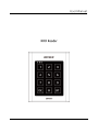
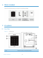
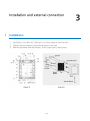
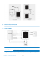
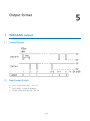
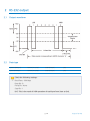
User Manual
RFID Reader
Table of contents
......................................................
ii
...................................................
1
.........................................
3
.................................................
4
...............................................................
4
.........................................................
5
.............................................................
5
..........................................................
5
......................................................
6
..........................................................
6
.....................................
7
.............................................................
7
.................................................
8
...............................................
8
..................
8
3 External connection
......................................................
9
3.1 Wiring Diagram
.......................................................
9
Table of contents
1
Safety Information
1 IMPORTANT SAFETY INSTRUCTIONS
2
Product introduction
1 Features
2 What's included
3 At a glance
3.1 Front / Rear
4 Cable color scheme
5 Cable selection
3
Installation and external connection
1 Installation
2 Precautions on installation
2.1 If installing on a metal wall
2.2 If installing more than one reader side by side or front and back
4
Initialization
. . . . . . . . . . . . . . . . . . . . . . . . . . . . . . . . . . . . . . . . . . . . . . . . . . . . . . . . 11
. . . . . . . . . . . . . . . . . . . . . . . . . . . . . . . . . . . . . . . . . . . . . . . . . . . . . . . . . 11
1 Basic operations
1.1 Initial state (when the power is supplied)
. . . . . . . . . . . . . . . . . . . . . . . . . . . . . . . . . . . . . . . . . . . . . . . . . . . . . . . . 11
1.2 Using the card
1.3 Using the keypad
. . . . . . . . . . . . . . . . . . . . . . . . . . . . . . . . . . . . . . . . . . . . . . . . . . . . . . 11
. . . . . . . . . . . . . . . . . . . . . . . . . . . . . . . . . . . . . . . . . . . . . . . . . . . . . . . . . . 11
1.4 LED Control
5
. . . . . . . . . . . . . . . . . . . . . . . . . . . . . . . . . . . . 11
1.5 Buzzer Control
. . . . . . . . . . . . . . . . . . . . . . . . . . . . . . . . . . . . . . . . . . . . . . . . . . . . . . . . 12
1.6 Tamper Control
. . . . . . . . . . . . . . . . . . . . . . . . . . . . . . . . . . . . . . . . . . . . . . . . . . . . . . . 12
Output format
. . . . . . . . . . . . . . . . . . . . . . . . . . . . . . . . . . . . . . . . . . . . . . . . . . . . . . 13
p.ii
1 WIEGAND output
. . . . . . . . . . . . . . . . . . . . . . . . . . . . . . . . . . . . . . . . . . . . . . . . . . . . . . . . 13
1.1 Timing Diagram
. . . . . . . . . . . . . . . . . . . . . . . . . . . . . . . . . . . . . . . . . . . . . . . . . . . . . . . 13
. . . . . . . . . . . . . . . . . . . . . . . . . . . . . . . . . . . . . . . . . . . . . . . . . . . 13
1.2 Data Format (34-bit)
. . . . . . . . . . . . . . . . . . . . . . . . . . . . . . . . . . . . . . . . . . . . . . . . . . . . . . . . . . 14
2 RS-232 output
2.1 Output waveform
. . . . . . . . . . . . . . . . . . . . . . . . . . . . . . . . . . . . . . . . . . . . . . . . . . . . . . 14
. . . . . . . . . . . . . . . . . . . . . . . . . . . . . . . . . . . . . . . . . . . . . . . . . . . . . . . . . . . . 14
2.2 Data type
. . . . . . . . . . . . . . . . . . . . . . . . . . . . . . . . . . . . . . . . . . . . . . . . . . 15
3 8 bit burst output format
3.1 8 bit burst output format
6
Troubleshooting
1 Troubleshooting
7
. . . . . . . . . . . . . . . . . . . . . . . . . . . . . . . . . . . . . . . . . . . . . . . . 15
. . . . . . . . . . . . . . . . . . . . . . . . . . . . . . . . . . . . . . . . . . . . . . . . . . . . 16
. . . . . . . . . . . . . . . . . . . . . . . . . . . . . . . . . . . . . . . . . . . . . . . . . . . . . . . . . 16
Product specifications
1 Product specifications
. . . . . . . . . . . . . . . . . . . . . . . . . . . . . . . . . . . . . . . . . . . . . . . . 18
. . . . . . . . . . . . . . . . . . . . . . . . . . . . . . . . . . . . . . . . . . . . . . . . . . . . 18
. . . . . . . . . . . . . . . . . . . . . . . . . . . . . . . . . . . . . . . . . . . . . . . . . . . . . . . 19
8
RMA Request
9
Warranty Policy and Limitation of Liability
Back cover
. . . . . . . . . . . . . . . . . . . . . . . . . . . . . . . . . 21
. . . . . . . . . . . . . . . . . . . . . . . . . . . . . . . . . . . . . . . . . . . . . . . . . . . . . . . . . . . . 23
p.iii
Table of contents
1
Safety Information
CAUTION: TO REDUCE THE RISK OF ELECTRIC SHOCK, DO NOT REMOVE COVER
(OR BACK) NO USER SERVICEABLE PARTS INSIDE. REFER SERVICING TO
QUALIFIED SERVICE PERSONNEL.
This symbol indicates that dangerous voltage consisting a risk of electric shock is
present within this unit.
This exclamation point symbol is intended to alert the user to the presence of
important operating and maintenance (servicing) instructions in the literature accompanying
the appliance.
WARNING
To reduce the risk of fire or electric shock, do not expose this appliance to rain or moisture.
WARNING
1.
Be sure to use only the standard adapter that is specified in the specification sheet.
Using any other adapter could cause fire, electrical shock, or damage to the product.
2.
Incorrectly connecting the power supply or replacing battery may cause explosion, fire,
electric shock, or damage to the product.
3.
Do not connect multiple controllers to a single adapter. Exceeding the capacity may
cause abnormal heat generation or fire.
4.
Securely plug the power cord into the power receptacle. Insecure connection may
cause fire.
p.1
5.
When installing the controller, fasten it securely and firmly. The fall of controller may
cause personal injury.
6.
Do not place conductive objects (e.g. screwdrivers, coins, metal parts, etc.) or
containers filled with water on top of the controller. Doing so may cause personal injury
due to fire, electric shock, or falling objects.
7.
Do not install the unit in humid, dusty, or sooty locations. Doing so may cause fire or
electric shock.
8.
If any unusual smells or smoke come from the unit, stop using the product. In such
case, immediately disconnect the power source and contact the service center.
Continued use in such a condition may cause fire or electric shock.
9.
If this product fails to operate normally, contact the nearest service center. Never
disassemble or modify this product in any way. (SAMSUNG is not liable for problems
caused by unauthorized modifications or attempted repair.)
10.
When cleaning, do not spray water directly onto parts of the product. Doing so may
cause fire or electric shock.
CAUTION
1.
Do not drop objects on the product or apply strong blows to it. Keep away from a
location subject to excessive vibration or magnetic interference.
2.
Do not install in a location subject to high temperature (over 50°C), low temperature
(below -30°C), or high humidity. Doing so may cause fire or electric shock.
3.
If you want to relocate the already installed product, be sure to turn off the power and
then move or reinstall it.
4.
Remove the power plug from the outlet when there is a lighting storm. Neglecting to
do so may cause fire or damage to the product.
5.
Keep out of direct sunlight and heat radiation sources. It may cause fire.
6.
Install it in a place with good ventilation.
7.
Avoid aiming the controller directly towards extremely bright objects such as sun.
8.
Apparatus shall not be exposed to dripping or splashing and no objects filled with
liquids, such as vases, shall be placed on the apparatus.
9.
The Mains plug is used as a disconnect device and shall stay readily operable at any
time.
p.2
Safety Information
1 IMPORTANT SAFETY INSTRUCTIONS
1.
Read these instructions.
2.
Keep these instructions.
3.
Heed all warnings.
4.
Follow all instructions.
5.
Do not use this apparatus near water.
6.
Clean only with dry cloth.
7.
Do not block any ventilation openings. Install in accordance with the manufacturer’s
instructions.
8.
Do not install near any heat sources such as radiators, heat registers, or other apparatus
(including amplifiers) that produce heat.
9.
Do not defeat the safety purpose of the polarized or grounding-type plug. A polarized
plug has two blades with one wider than the other. A grounding type plug has two
blades and a third grounding prong. The wide blade or the third prong is provided for
your safety. If the provided plug does not fit into your outlet, consult an electrician for
replacement of the obsolete outlet.
10.
Protect the power cord from being walked on or pinched particularly at plugs,
convenience receptacles, and the point where they exit from the apparatus.
11.
Only use attachments/accessories specified by the manufacturer.
12.
Use only with cart, stand, tripod, bracket, or table specified by the manufacturer, or
sold with the apparatus.
13.
Unplug this apparatus when a card is used. Use caution when moving the cart/
apparatus combination to avoid injury from tip-over.
14.
Refer all servicing to qualified service personnel. Servicing is required when the
apparatus has been damaged in any way, such as power supply cord or plug is
damaged, liquid has been spilled or objects have fallen into the apparatus, the
apparatus has been exposed to rain or moisture, does not operate normally, or has
been dropped.
Safety Information
p.3
2
Product introduction
1 Features
This model is an elegant-looking proximity reader that is featured by the capacitive
touch-sensing keypad. The back-lighted keypad is useful especially for night operation, and
its epoxy adhesion and aluminium case relieve you of worries about the rain or any other
challenging weather conditions. This model permits user access through authentication of
the presented proximity card and personal identifi cation number using the keypad. With its
red, green and orange indicators as well as the Piezo buzzer, this model is guaranteed to
make a stable and correct operation.
●
13.56 MHz [MIFARE] Contactless Smart Card & PIN Reader
●
Compatible with ISO14443 Type A
●
34 bit Wiegand & RS-232 Data Output
●
8 Bit Burst Output Format supported
●
Numeric keypad with backlighting for night operation
●
Control of External LED Indicators
●
Control of External Buzzer
●
Tamper Switch
●
Reverse Polarity Protection
●
Weatherproof and Dustproof
p.4
2 What's included
Check if the following items are included in the product package.
3 At a glance
3.1
Front / Rear
Figure 2-1
rf10structure
1. LED
Product introduction
Displays the status of the system operation.
p.5
2. Keypad
Used to enter the ID/password.
3. Tamper Switch
A tamper switch to detect falling from the wall.
4. Connection Cable
Used to connect to the power or I/O cable.
5. Buzzer
Piezo buzzer.
6. Fixing Hole
Fixing hole for wall-mounting.
4 Cable color scheme
Item
Cable color
Signal Line
Description
Power
Red
DC + 12V
Power (+12V)
Black
GND
Earth-grounding for power
Green
WIK_DATA0
Wiegand Data 0 Output Port
White
WIK_DATA1
Wiegand Data 1 Output Port
Purple
TX_OUT
RS-232 Output Terminal
Orange
Not used
Not used.
Brown
Not used
Not used.
Yellow
Green LED control
Green LED Control Input Terminal
Gray
Orange LED Control
Orange LED Control Input Terminal
Blue
Buzzer Control
BUZZER Control Input Port
Pink
Tamper (COM)
COM Port of Tamper Switch
Light yellow
Tamper (NC)
NC Port of Tamper Switch
Black
GND
GND
Output
Not used
Input
Tamper
RS-232 GND
5 Cable selection
Item
Cable type
Power (DC12V)
Belden #9409, 18 AWG 2 Conductor, Unshielded
Card/PIN data (Wiegand)
Belden #9512, 22 AWG 4 Conductor, Shielded
Control Signal (LED,BUZZER)
Belden #9514, 22 AWG 8 Conductor, Shielded
TAMPER
RS-232 Cable
Belden #9829, 24 AWG 2-twisted pair, Shielded
p.6
Product introduction
Installation and external connection
1 Installation
1.
See [Figure 1] to drill 6-32” holes and 1/2” holes (totally 4) into the wall.
2.
Tighten the four screws to secure the product to the wall.
3.
With the provided 3mm hex wrench, fix the outer case to the product.
p.7
3
2 Precautions on installation
2.1
If installing on a metal wall
If you install the reader on a metal wall, the read range may be reduced.
To avoid this problem, it is recommended to insert the spacer between the metal wall and
the reader as shown below.
2.2
If installing more than one reader side by side or front and back
If you install more than one reader side by side or front and back, the read range may be
reduced. In this case, if you present a card to one reader, the other reader may recognize
the same card, meaning both readers read the same card simultaneously.
To avoid this problem, keep at least 20 cm of space between the two readers.
p.8
Installation and external connection
3 External connection
3.1
Wiring Diagram
Item
Cable Wiring
Power Supply Unit
Connect the DC+12V to the red line.
Connect GND to the black line.
Wiegand Connection
Connect the green line of the product to the Wiegand D0 input port of the
Installation and external connection
p.9
Item
Cable Wiring
controller.
Connect the white line of the product to the Wiegand D1 input port of the
controller.
LED Control
Enables you to turn on or off the LED indicators.
To control green indicator, connect the yellow line to the controller’s
output (relay). Connect the Gray to control the orange indicator, connect
the white with red stripes to control the red indicator. See 1.4 LED Control
Buzzer Control
Enables you to turn on or off the buzzer.
To control the buzzer, connect the blue line to the controller’s output
(relay). See 1.5 Buzzer Control
RS-232 Connection
Connect to the COM port of the PC. (Connect pin 2 of the DB-9 connector
to the purple line; connect the black of the device (RS-232 GND) to pin 5
of the DB-9 connector)
Tamper control
Connect the COM port (Pink line) of the product’s tamper switch to GND;
connect the NC port (Light yellow) of the tamper switch to the input port
of the controller.
p.10
Installation and external connection
4
Initialization
1 Basic operations
1.1
Initial state (when the power is supplied)
When you apply power to the product, it will sound beep three times before entering
Standby with the red indicator turned on.
1.2
Using the card
Present the card to the product until you hear a beep and the green indicator turns on.
The reader keeps the green indicator turned on while transferring the card data to the
controller. When it is done, the green indicator turns off and for receiving the next card, the
red indicator stays ON.
1.3
Using the keypad
Hold down the keypad until you hear a beep. The reader transfers the keypad data to the
controller.
As soon as you press the keypad, the orange indicator turns on, followed by the reader
transferring the keypad data to the controller. Then, only the red indicator turns on.
1.4
LED Control
You can control both green and orange indicators at will.
To control the green indicator, connect the green-indicator control line (yellow) to NO of
the controller relay output, and connect COM to GND. Set I/O of the controller; now you
can control turning on/off the indicator.
p.11
You can turn on/off the indicators according to the I/O settings of the controller, which can
be applied to various situations. For more information about the I/O settings of the
controller, refer to the user manual of the controller.
To control the orange indicator, connect the gray line to NC of the controller.
1.5
Buzzer Control
Connect the buzzer control input line (blue) to the NO port of the controller relay output,
and GND to the COM port.
You can configure the I/O settings of the controller so that it beeps. If the product continues
to beep, it means that the buzzer control is working properly.
The controller can use the I/O settings to set the buzzer control so that it sounds an
additional beep for authorized or unauthorized access upon user authentication.
Furthermore, you can make various modifi cations according to the different I/O settings of
the controller.
For more information about the I/O settings of the controller, refer to the user manual of
the controller.
Card reading is not available while the buzzer control is sounding the buzzer.
1.6
Tamper Control
You can set the signal that you want to output if the device is dismantled forcibly.
Connect the COM port (Pink line) of the product’s tamper switch to GND; connect the NC
port (Light yellow) of the tamper switch to the input port of the controller. If the tamper of
the reader operates, the controller produces an input signal and generates the
corresponding output depending on the controller setting.
p.12
Initialization
5
Output format
1 WIEGAND output
1.1
Timing Diagram
1.2
Data Format (34-bit)
●
Bit 1 : Even Parity (bit 2 ~ bit 17)
●
Bit 2~Bit33 : 4-byte ID Number
●
Bit 34 : Odd Parity (bit 18 ~ bit 33)
p.13
2 RS-232 output
2.1
Output waveform
2.2
Data type
START (0X02H)
DATA (10 Char)
END (0x03H)
LRC
START(0X02H)
DATA (10 Char)
END (0x03H)
LRC
Check the following settings:
Baud Rate : 9600bps
Data Bit : 8
Parity Bit : None
Stop Bit : 1
LRC: This is the result of XOR operation of each byte from Start to End.
p.14
Output format
3 8 bit burst output format
3.1
8 bit burst output format
Keypads
Binary
Hexa
Keypads
Binary
Hexa
0
11110000
F0
6
10010110
96
1
11100001
E1
7
10000111
87
2
11010010
D2
8
01111000
78
3
11000011
C3
9
01101001
69
4
10110100
B4
ESC
01011010
5A
5
10100101
A5
ENT
01001011
4B
Output format
p.15
6
Troubleshooting
1 Troubleshooting
If the product does not function properly, please see the below for trouble shooting.
Problem
Solution
My card is not read
1) Check the rated voltage specified in the user manual and the catalog.
properly.
2) Ensure that you are using an ISO14443 Type A card.
- Cards of 125 kHz format can not be used. However, the 13.56 MHz card
cannot be used if it is of Type B, ISO15693.
(Contact the card retailer regarding the card format.)
3) If the problem persists, contact the nearest customer service for your
assistance.
When I turn on the
1) Ensure that you are using a larger-capacity adapter than specifi ed in the
product, it sounds a
user manual or the catalog, which should cover the rated current
beep with dimly turned
consumption of the reader. If you are using multiple readers that are
on indicator.
connected to one adapter, make sure that the adapter should be large
enough to cover the current consumption multiplied by the reader count.
2) Even with a large adapter enough to supply adequate power, if the
power cable is not a dedicated line (such as communication line or UPT
cable), or if it’s so long to cause power loss, you’d better replace it with a
dedicated line or reinforce it.
3) If the problem persists, contact the nearest customer service for your
assistance.
The read range (R/R) of
1) The characteristics of a card are determined by the nature of the coils
the card differs each
used and in the manufacturing process engaged by the card manufacturer.
time the product reads
So what you do fi rst is to check that the cards in use are made by the
the card.
same manufacturer. If you are using cards from different card makers, the
read range (R/R) differs by the card, which is the result of normal
operation.
p.16
Problem
Solution
2) If you encounter a different read range for each card that is made by the
same manufacturer, please contact the nearest customer service.
Troubleshooting
p.17
7
Product specifications
1 Product specifications
Item
SRK101-V
Power / Current
DC 12V / Max.150mA
Reading Time (Card)
30ms
Input Port
2ea : External LED Control, External Buzzer Control
Output Port
34bit Wiegand, 8bit Burst for PIN
LED Indicator
3 LED Indicators (Red, Green and Orange)
Beeper
Piezo Buzzer
Keypad
12 Key Touch Keypad with Back Lighting
Operating Temperature
-25°C to +50°C
Operating Humidity
10% to 90% relative humidity non-condensing
Color / Material
Silver with Black/Polycarbonate & Aluminum Die casting
Dimension
87.0 x 109.0 x 25.0
(W x H x D(mm))
Weight
350g ±10
p.18


![13.56MHz [MIFARE] Contactless Smart Card](http://vs1.manualzilla.com/store/data/005689074_1-1b5ba2b7f854420e24ee51932ec4423a-150x150.png)