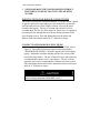
1
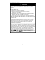
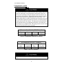
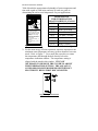
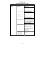
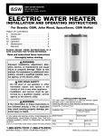
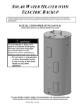
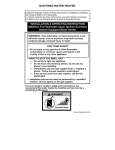
INDIRECT-FIRED WATER HEATER A Spanish language version of these instructions is available by contacting the manufacturer listed on the rating plate. La version espanola de estas instruccions se puede obtener al escribirle a la fábrica cuyo nombre aparece in la placa de especificaciones. WARNING To avoid damage or injury, there must be no materials stored against the indirect water heater and proper care shall be taken to avoid unnecessary contact (especially by children) with the indirect water heater. Do not store or use gasoline or other flammable liquids in the vicinity of this water heater or any other appliance. INSTALLATION/OPERATING MANUAL WITH PARTS LISTING AND TROUBLESHOOTING GUIDE For your family’s comfort, safety, and convenience, we recommend this water heater be installed and serviced by a plumbing professional. 238-43480-00G REV 10/13 CONGRATULATIONS! You have just purchased one of the finest water heaters on the market today! This installation, operation, and instruction manual will explain in detail the installation and maintenance of your new indirect water heater. We strongly recommend that you contact a plumbing professional for the installation of this water heater. We require that you carefully read this manual, as well as the enclosed warranty, and refer to it if questions arise. If you have any specific questions concerning your warranty, please consult the plumbing professional from whom your water heater was purchased. For your records we recommend that you write the model, serial number and installation date of your water heater in the back of this manual. This manual should be kept with the water heater. We’re committed to providing you with the finest water heater made. 2 CAUTION The maximum boiler water supply temperature to the indirect heat exchanger must not exceed 240°F (115°C). NOTICE Insulation blankets are not required for this water heater. This water heater meets or exceeds the ASHRAE/IES 90.1b standards with respect to insulation and standby loss requirements. TABLE OF CONTENTS IIIIIIIVVVIVIIVIIIIXX- IMPORTANT INFORMATION…………….….. SPECIFICATIONS………………………………. GENERAL INFORMATION……………………. PRE-INSTALLATION…………………………… WATER CONNECTIONS……………………….. ELECTRICAL CONNECTIONS……………….. OPERATING INSTRUCTIONS………………… MAINTENANCE…………………………………. TROUBLESHOOTING GUIDE………………… PARTS LIST………………………………………. NOTES…………………………………………….. 3 4 8 12 15 20 25 26 29 32 34 36 SECTION I IMPORTANT INFORMATION -READ CAREFULLYThe equipment must be installed in accordance with those installation regulations required in the area where the installation is to be made. These regulations must be carefully followed in all cases. Authorities having jurisdiction shall be consulted before installations are made. All wiring on water heaters installed in the USA must be in accordance with the National Electrical Code and/or local regulations; or in Canada, installed in accordance with the Canadian Electrical Code and/or local regulations. The following terms are used throughout this manual to bring attention to the presence of hazards of various risk levels, or to important information concerning product life. CAUTION DANGER Indicates a potentially hazardous situation, which, if not avoided, may result in moderate, or minor injury or property damage. Indicates an imminently hazardous situation, which, if not avoided, will result in death, serious injury, or substantial property damage. NOTICE WARNING Indicates special instructions on installation, operation or maintenance, which are important but not related to personal injury hazards. Indicates a potentially hazardous situation, which, if not avoided, could result in death, serious injury, or substantial property damage. 4 Important Information continued- DANGER DO NOT store or use gasoline or other flammable, combustible, or corrosive vapors and/or liquids in the vicinity of this or any other appliance. IF YOU SMELL GAS: DO NOT try to light any appliance. DO NOT touch any electric switch; do not use any telephone in your building. Immediately call your gas supplier from a telephone in another building. Follow the gas supplier’s instructions. If you cannot reach your gas supplier, call the fire department DO NOT OPERATE THE APPLIANCE UNTIL THE LEAKAGE IS CORRECTED! Liquefied petroleum gas/propane gas is heavier than air and will remain at floor level if there is a leak. Basements, crawl spaces, closets, and areas below ground level will serve as pockets for accumulation of leaking gas. This water heater is supplied with an adjustable thermostat to control water temperature. Hot water temperatures required for automatic dishwasher and laundry use can cause scald burns resulting in serious personal injury and/or death. The temperature at which injury occurs varies with the person’s age and the time of exposure. The slower response time of disabled persons increases the hazards to them. NEVER allow small children to use a hot water tap or to draw their own bath water. NEVER leave a child or disabled person unattended in a bathtub or shower. 5 Important Information continued- WARNING Installation is not complete unless a pressure and temperature relief valve is installed into the side of the water heater. See the Water Connections section of this manual for details. This water heater contains very hot water under high pressure. Do not unscrew any pipe fittings or attempt to disconnect any components of this water heater without positively assuring the water is cool and has no pressure. Always wear protective clothing and equipment when installing, starting up, or servicing this water heater to prevent scald injuries. Do not rely on the pressure and temperature gauges to determine the temperature and pressure of the water heater. This water heater contains components that become very hot. Do not touch any components unless they are cool. Improper installation, adjustments, alteration, service or maintenance can cause property damage, personal injury or loss of life. Failure to follow all instructions in the proper order can cause personal injury or death. Read and understand all instructions, including all those contained in component manufacturer’s manuals, which are provided with the appliance before installing, starting-up, operating, maintaining, or servicing this appliance. Keep this manual and literature in legible condition and posted near the appliance for reference by owner and service technician. This water heater requires regular maintenance and service to operate safely. Follow the instructions contained in this manual. Installation, maintenance, and service must be performed only by an experienced, skilled, and knowledgeable installer or service agency. To comply with NSF requirements this water heater is to be: a) Sealed to the floor with sealant, in a smooth and easily cleanable way, or b) Installed with an optional leg kit that includes legs and/or extensions that provide a minimum clearance of 6” beneath the water heater. 6 Important Information continued- WARNING It is the responsibility of the installing contractor to see that all controls are correctly installed and are operating properly when the installation is complete. DO NOT operate the water heater with jumpered or absent controls or safety devices. DO NOT tamper with or alter the water heater and/or controls. DO NOT operate the water heater if any external part has been under water. Immediately call a qualified service technician to inspect the appliance and to replace any part of the control system that was under water. This water heater is suitable for installation on combustible flooring. DO NOT install this water heater on carpeting. DO NOT operate this water heater without first being certain it is filled with water. Flammable items, pressurized containers, or any other potential fire hazardous articles must never be placed on or adjacent to the heater. Containers of flammable gases should not be stored or used in the same room with this water heater. Hydrogen gas can be produced in an operating water heater that has not had water drawn from the tank for a long period of time (generally two weeks or more). Hydrogen gas is extremely flammable. To prevent the possibility of injury under these conditions, we recommend that the water faucet be opened for several minutes at the kitchen sink before you use any electrical appliance that is connected to the hot water system. If hydrogen is present, there will be unusual sounds such as air escaping through the pipes as hot water begins to flow. Do not smoke or have open flame near the faucet at the time it is open. 7 SECTION II SPECIFICATIONS Figure 1 – Tank Layout Table 1: Water Heater Dimension (Inches) MODEL A 30-Gal. / Res. 22 40-Gal. “R” / Res. 22 50-Gal. “R” / Res. 22 65-Gal. / Res. 22 65-Gal. / Com. 22 80-Gal. / Res. 24 80-Gal. / Com. 24 120-Gal. / Res. 28-1/4 120-Gal. / Com. 28-1/4 B C D E F 33-5/8 41-1/8 46-1/4 59-1/4 59-1/4 59 59 62-1/2 62-1/2 28-1/4 34-3/8 40-1/8 53-1/8 53-1/8 52-7/8 52-7/8 55-3/4 55-3/4 34-3/8 41-7/8 47 60 60 59-3/4 59-3/4 63-1/4 63-1/4 5-3/8 5-3/8 5-3/8 5-3/8 5-3/8 5-3/8 5-3/8 6-3/8 6-3/8 27-1/2 27-1/2 27-1/2 27-1/2 47-3/4 27-1/2 47-3/4 28-1/2 48-3/4 8 Specifications continued- Table 2: Water Heater Capacities MODEL Tank Capacity (Gal) Coil Volume (Gal) 30-Gal. / Res. 40-Gal. “R” / Res. 50-Gal. “R” / Res. 65-Gal. / Res. 65-Gal. / Com. 80-Gal. / Res. 80-Gal. / Com. 120-Gal. / Res. 120-Gal. / Com. 30 38 48 60 58 75 73 116 114 2.7 2.7 2.7 2.7 5.0 2.7 5.0 2.7 5.0 Dry Weight Wet Weight (Lbs) (Lbs) 140 172 180 196 265 224 293 355 415 404 486 576 704 768 861 920 1324 1370 Table 3: AHRI Certified Water Heater Ratings First Hour Rating (Gal/Hr) MODEL 30-Gal. / Res. 40-Gal. “R” / Res. 50-Gal. “R” / Res. 65-Gal. / Res. 65-Gal. / Com. 80-Gal. / Res. 80-Gal. / Com. 120-Gal. / Res. 120-Gal. / Com. 255 260 265 275 405 295 415 315 445 Standby Minimum Heat Continuous Heat Loss Output Rate of Draw Rating Rating the Heat Source (Gal/Hr) (BTU/Hr) (°F/Hr) 235 235 235 235 370 235 370 235 370 1.2 1.1 0.9 0.8 0.8 0.6 0.6 0.4 0.4 157,000 157,000 157,000 157,000 245,000 157,000 245,000 157,000 245,000 Minimum Heat Source Flow Rate (Gal/Min) 13.7 13.7 13.7 13.7 14.0 13.7 14.0 13.7 14.0 NOTES: These ratings were obtained with a heat source output rate and flow rate as specified in Table 3 and a 180°F boiler water supply temperature. Other results will be obtained under different conditions. 9 Specifications continued- Table 4: Water Heater Performance Maximum First Hour Rating (Gal/Hr) @ MODEL 140 °F 30-Gal. / Res. 279 288 297 306 534 321 546 357 583 40-Gal. “R” / Res. 50-Gal. “R” / Res. 65-Gal. / Res. 65-Gal. / Com. 80-Gal. / Res. 80-Gal. / Com. 120-Gal. / Res. 120-Gal. / Com. 115 °F Approximate Boiler Output Needed For Ratings (BTU/hr) 6.7 6.7 6.7 6.7 12.8 6.7 12.8 6.7 12.8 220,000 220,000 220,000 220,000 420,000 220,000 420,000 220,000 420,000 Continuous Draw Rating (Gal/Min) @ 115 °F 140 °F 429 438 447 456 820 470 834 507 871 4.2 4.2 4.2 4.2 8.0 4.2 8.0 4.2 8.0 NOTES: Based on 200°F boiler water temperature and 50°F potable water inlet temperature. Table 5: Water Heater Performance MODEL 30-Gal. / Res. 40-Gal. “R” / Res. 50-Gal. “R” / Res. 65-Gal. / Res. 65-Gal. / Com. 80-Gal. / Res. 80-Gal. / Com. 120-Gal. / Res. 120-Gal. / Com. Hot Water Availability (Minutes) 5.5 7.5 9.0 11.0 10.5 13.5 13.2 20.8 20.6 Pressure Drop at Coil Heat Rated Heat Source Transfer Area Flow Rate (Sq Ft) (Feet of Head) 1.5 14.2 1.5 14.2 1.5 14.2 1.5 14.2 5.0 27.2 1.5 14.2 5.0 27.2 1.5 14.2 5.0 27.2 10 Specifications continued- NOTICE If the boiler takes longer to heat up from a cold start than the water availability as noted above, hot water shortage may occur. Hot water availability is based off drawing 80% of the heated tank volume at 4 gallons per minute flow rate. The maximum heat transfer through the coil (heat input) of the water heater at 240°F boiler water supply temperature and 210°F potable water temperature is 94,100 Btu/hr for residential models and 180,300 Btu/hr for commercial models. Potable water temperature is limited to below 210°F and nominal watercontaining capacity is below 120 gallons for all indirect-fired models. Accordingly, per Part HLW-101.2, Section IV of the ASME Boiler and Pressure Vessel Code, all indirect-fired products listed are exempted from compliance with the code. 11 SECTION III GENERAL INFORMATION FEATURES This water heater contains the following features: HEAT EXCHANGER – The heat exchanger (coil) has 1” NPT female fittings. These water heaters with single-wall heat exchangers meets the Uniform Plumbing Code for installation in all potable water systems provided that: The boiler water (including additives) is practically non-toxic, having toxicity rating of class of 1 as listed in Clinical Toxicology of Commercial Products. The boiler water pressure is limited to maximum 30 psig by approved relief valve. The heat transfer medium is potable water or contains only substances that are recognized as safe by the U.S. Food and Drug Administration (FDA). The pressure of the heat transfer medium is maintained less than the normal minimum operating pressure of the potable water system. The equipment is permanently labeled to indicate that only additives recognized as safe by the FDA shall be used in the heat transfer medium. ADJUSTABLE AQUASTAT – The temperature may be adjusted from 80°F to 160°F. The aquastat (thermostat) was adjusted to 120°F before the heater was shipped from the factory. It is recommended that lower temperatures be used to avoid the risk of scalding. Refer to the “Warnings” and the section on SCALDING in “Section VII – Operating Instructions.” It is further recommended, in all cases, that the water temperature be set for the lowest temperature that satisfies your hot water needs. This will also provide the most energy efficient operation of the water heater and minimizes scale formation. Setting the water heater temperature at 120°F will reduce the risk of scalds. Some states require settings to specific lower temperatures. 12 General Information continued- TEMPERATURE AND PRESSURE RELIEF VALVE WARNING Keep clear of the combination temperature and pressure relief valve discharge line outlet. The discharge may be hot enough to cause scald injury. The water is under pressure and may splash. For protection against excessive temperatures and pressure, install temperature and pressure protective equipment required by local codes, but not less than a combination temperature and pressure relief valve certified by a nationally recognized testing laboratory that maintains periodic inspection of production of listed equipment or materials as meeting the requirements of the Standard for Relief Valves and Automatic Gas Shutoff Devices for Hot Water Supply Systems, ANSI Z21.22 and the Standard CAN1-4.4 Temperature, Pressure, Temperature and Pressure Relief Valves and Vacuum Relief Valves. The combination temperature and pressure relief valve must be marked with a maximum set pressure not to exceed the maximum working pressure of the water heater. The combination temperature and pressure relief valve must also have an hourly rated temperature steam BTU discharge capacity not less than the hourly rating of the water heater. The supplied combination temperature and pressure relief valve, when properly installed and unrestricted, will discharge the maximum input produced by a 240°F (115°C) boiler supply temperature. A lower boiler supply temperature will reduce the input required to be discharged in the event of excessive potable water temperatures. Install the combination temperature and pressure relief valve into the opening provided and marked for this purpose on the water heater. Some models may already be equipped or supplied with a temperature and pressure relief valve. Verify that the combination temperature and pressure relief valve complies with local codes. If the temperature and pressure relief valve does not comply with local codes, replace it with one that does. 13 General Information continued- WARNING Install a discharge line so that water discharged from the temperature and pressure relief valve will exit within six (6) inches above, or any distance below, the structural floor and cannot contact any live electrical part. The discharge line is to be installed to allow for complete drainage of both the temperature and pressure relief valve and the discharge line. The discharge opening must not be subjected to blockage or freezing. DO NOT thread, plug, or cap the discharge line. It is recommended that a minimum clearance of four (4) inches be provided on the side of the water heater for servicing and maintenance of the combination temperature and pressure relief valve Do not place a valve between the combination temperature and pressure relief valve and the tank! SACRIFICIAL ANODES – Three sacrificial anode rods have been installed in the tank head to extend tank life. The anode rods should be inspected annually to determine the amount of sacrificial decay and replaced when necessary to prolong tank life. Water conditions in your area will influence the time interval for inspection and replacement of the anode rod. The use of a water softener may increase the speed of anode consumption. More frequent inspection of the anode is needed when using softened (or phosphate treated) water. Contact the plumbing professional who installed the water heater or the manufacturer, listed on the rating plate, for anode replacement information. 14 SECTION IV PRE-INSTALLATION UNPACKING INSPECT SHIPMENT carefully for any signs of damage. If damage is noted, do not install the product. Contact the shipper or manufacturer. All equipment is carefully manufactured, inspected, and packed. Our responsibility ceases upon delivery of the packaged heater to the carrier in good condition. NOTE: Any claims for damage or shortage in shipment must be filed immediately against the carrier by the consignee. IMPORTANT DECISIONS REQUIRED BEFORE INSTALLATION SIZING 1. Boiler DOE Heating Capacity – The indirect-fired water heater will provide the rated performance only if used in conjunction with a heat source with a DOE heating capacity (Boiler Output) at least as much as the minimum noted in Table 3. If the heat source has less capacity, the output of the tank will be reduced. To determine the approximate reduction in output from the tank use the following formula: New Rating = (maximum continuous draw rating) x Actual Boiler Output Capacity Minimum Boiler Output Capacity For example, what would the continuous draw rating be if a 50-gallon indirect-fired heater were installed with a heat source having a DOE heating capacity of 125,000 BTU/h? Answer: New Rating = 235 gal/hr x (125,000 BTU/h)/(157,000 BTU/h) = 235 gal/hr x 0.796 = 187 gal/hr 15 Pre-installation continued- NOTICE Increasing the boiler DOE heating capacity above the values listed in Table 3 will not increase the rating of the water heater. 2. Circulator Sizing – Refer to Table 5 for the corresponding pressure drop through the coil for the given model. Calculate the pressure drop of all straight pipe and fittings on the supply and return of the water heater at the selected flow rate. Add the piping/fitting pressure drop to the pressure drop through the water heater coil. Select a circulator that will provide an appropriate flow rate at the combined pressure drop. SYSTEM ZONE CONTROL The indirect-fired water heater must be installed as a zone separate from the space heating system. The domestic hot water zone’s piping and circulator must be sized for a minimum flow rate with all zones in use and a maximum flow rate with only the water heater in use. For this reason, the preferred method of zone control is with circulators. 1. Circulators – With space heating zones using circulators, the indirect-fired heater should be added as an additional zone with a circulator. 2. Zone Valves – Select a valve with a low-pressure drop to assure adequate flow through the water heater. 3. Hybrid – The space heating zone can be zoned using zone valves and the indirect-fired heater zoned with a circulator. 16 Pre-installation continued- DOMESTIC HOT WATER PRIORITY Two options are available, Priority and Non-Priority. 1. Priority – Demand for space heating is interrupted or postponed until the domestic hot water demand is satisfied. This option provides maximum delivery of domestic hot water. Priority is recommended when: a) Boiler net output is 100,000 Btu per hour or less, or b) When boiler output required to satisfy domestic hot water demand is at least 50% of the boiler output required to satisfy space heating demand, or c) When an interruption in space heating can be tolerated during a long domestic hot water draw. 2. Non-Priority – Boiler output is divided between space heating and domestic hot water heating. Delivery of domestic hot water can be reduced during simultaneous space and domestic hot water heating operations, depending on such factors as boiler output, boiler over-sizing, number of space heating zones calling for heat, and the ratio of domestic hot water load to space heating load. 17 Pre-installation continued- Component Location CAUTION This water heater must be located in an area where leakage of the tank, water line connections, or the temperature and pressure relief valve will not result in damage to the area adjacent to the water heater or to lower floors of the structure. When such locations cannot be avoided, a suitable drain pan must be installed under the water heater. The drain pan depth must be suitable for draining and collecting water, and have a minimum length and width of at least four (4) inches measured from the jacket of the water heater. The drain pan, as described above, can be purchased from your plumbing professional. The drain pan must be piped to an adequate drain. The piping must be at least ¾ inch in diameter and pitched for proper drainage. Clearance from Combustible Materials Top Sides Front Rear 0” 0” 0” 0” Table 6: Combustible Material Clearances Recommended Service Clearances Non-Piping Side 4” Front T & P Relief (Aquastat) Rear Valve Side 16” 0” 4” Table 7: Service Clearances CAUTION Do not drop water heater. Do not bump water heater jacket against floor. 18 Pre-installation continued- Appliance Location 1. Boiler Location – Locate the indirect-fired water heater as close to the boiler as practical. 2. Fixture Locations – For fastest delivery of hot water, place the indirect-fired water heater close to points of use. Additional Recommended Components 1. Shut-off Valves – Allows isolation of water heater from domestic water system and/or boiler system during service. 2. Unions – Allows water heater movement during service if adequate clearance cannot be provided. 3. Thermal Expansion Tank – If the water heater is installed in a closed water supply system, such as one having a back-flow preventer in the cold water line, provide thermal expansion control. Contact the water supplier or local plumbing inspector for additional information. WARNING Do not plug the inlet and outlet tappings of tankless heater left installed in the boiler. MOVE THE WATER HEATER TO A PERMANENT POSITION BY SLIDING OR WALKING. NOTICE For California installation this water heater must be braced, anchored, or strapped to avoid falling or moving during an earthquake. See instructions for correct installation procedures. Instructions may be obtained from DSA Headquarters Office, 1102 Q Street, Suite 5100, Sacramento, California 95811. 19 SECTION V WATER CONNECTIONS WARNING FAILURE TO INSTALL AND MAINTAIN A NEW, LISTED TEMPERATURE AND PRESSURE RELIEF VALVE WILL RELEASE THE MANUFACTURER FROM ANY CLAIM WHICH MIGHT RESULT FROM EXCESSIVE TEMPERATURE AND PRESSURES. Hydrogen gas can be produced in an operating water heater that has not had water drawn from the tank for a long period of time. HYDROGEN GAS IS EXTREMELY FLAMMABLE. To prevent the possibility of injury under these conditions, we recommend the hot water faucet be opened for several minutes at the kitchen sink before you use any electrical appliance that is connected to the hot water system. If hydrogen is present, there will be an unusual sound such as air escaping through the pipes as hot water begins to flow. Do not smoke or have open flame near the faucet at the time it is open. Keep clear of the temperature and pressure relief valve discharge line outlet. The discharge may be hot enough to cause scald injury. The water is under pressure and may splash. CAUTION If sweat fittings are to be used, DO NOT apply heat to the nipples on top of the water heater. Sweat the tubing to the adapter before fitting the adapter to the water connections. It is imperative that heat is not applied to the nipples containing a plastic liner. 20 Water Connections continued- INSTALL TEMPERATURE AND PRESSURE RELIEF VALVE (if not factory installed) WARNING Temperature and pressure relief valve discharge piping must be piped near the floor to eliminate potential of severe burns. Do not pipe in any area where freezing could occur. Do not install any shut-off valves, plugs or caps to the temperature and pressure relief valve or piping. INSTRUCTIONS FOR POTABLE CONNECTIONS 1. BEFORE PROCEEDING WITH THE INSTALLATION, CLOSE THE MAIN WATER SUPPLY VALVE. After shutting off the main water supply, open a faucet to relieve the water line pressure to prevent any water from leaking out of the pipes while making the water connections to the water heater. After the pressure has been relieved, close the faucet. The COLD water inlet and HOT water outlet are identified on the top of the water heater. Make the proper plumbing connections between the water heater and the plumbing system to the house. Install a shut-off valve in the cold water supply line. 2. If this water heater is installed in a closed water supply system, such as one having a back-flow preventer in the cold water supply, provisions must be made to control thermal expansion. DO NOT operate this water heater in a closed system without provisions for controlling thermal expansion. Warranties do not cover damages from thermal expansions such as pressure bulges and/or deformities. A properly sized expansion tank will alleviate most problems. Your water supplier or local plumbing inspector should be contacted on how to control this situation. 3. After installation of the water lines, open the main water supply valve and fill the water heater. While the water heater is filling, open several hot water faucets to allow air to escape from the water system. When steady streams of water flow through the faucets, close them and check all water connections for possible leaks. 21 Water Connections continued- 4. NEVER OPERATE THE WATER HEATER WITHOUT FIRST BEING CERTAIN THAT IT IS FILLED WITH WATER. INSTRUCTIONS FOR BOILER CONNECTIONS The indirect-fired heater connection labeled “To Boiler Return” should be piped to the boiler return piping as close to the boiler as possible and especially after any flow control or check valves in the space heating return piping. The use of a union and a shut-off valve is recommended. The use of a flow control or check valve is required to prevent back flow through the water heater during operation of the space heating system. Pipe and fittings between the boiler and indirect-fired water heater should be ¾” diameter or larger. CONNECT WATER BOILER SUPPLY PIPING 1. For a space heating system that utilizes ZONE VALVES, refer to Figure 2. The indirect-fired water heater connection labeled “FROM BOILER SUPPLY” should be piped to the boiler supply piping. Mount the circulator making sure the flow arrow points toward the water heater. The use of shut-off valves and unions are recommended for future service convenience. The use of an air separator and vent is recommended to eliminate air in the system. Pipe and fittings between the boiler and indirect-fired water heater must be ¾” diameter or larger. CAUTION Maximum boiler water supply temperature to the indirect heat exchanger must not exceed 240°F (116°C). 22 Water Connections continued- Figure 2 - Water Boiler Piping with Zone Valves 2. For a space heating system that utilizes CIRCULATORS, refer to Figure 3. The indirect-fired water heater connection labeled “FROM BOILER SUPPLY” should be piped to the boiler supply piping. Mount the circulator making sure the flow arrow points toward the water heater. The use of shut-off valves and unions are recommended for future service convenience. The use of an air separator and vent is recommended to eliminate air in the system. Pipe and fittings between the boiler and indirect-fired water heater must be ¾” diameter or larger. Figure 3 - Water Boiler Piping with Circulators 23 Water Connections continued- CONNECT STEAM BOILER SUPPLY PIPING Figure 4 represents a typical steam boiler connection diagram. Refer to the boiler installation manual or contact the boiler manufacturer for an appropriate piping diagram. The use of a union, shut-off valves, and a drain valve is recommended for future service convenience. The use of an in-line “Y”-style strainer is required to prevent accumulation of sludge in the water heater’s coil. Figure 4 - Typical Steam Boiler Connections (connections available below the water line) NOTICE Typical steam boiler without connections available below the water line is not recommended due to insufficient water temperature, especially during warmer months when the space heating system is not operational. Boiler water temperature at the bottom of a steam boiler can be 50°F lower than the boiler’s water temperature limit setting during such periods. FILL BOILER SYSTEM 1. On new boiler installations, do not purge the boiler or space heating system through the water heater. During any boiler or space heating system flushing, cleaning, or purging, the water heater should be isolated to avoid possible attack on the carbon steel coil by chemical additives. 2. Purge air from boiler/water heater piping. 3. Check system for leaks. Repair as necessary. 24 SECTION VI ELECTRICAL CONNECTIONS Install electric wiring in accordance with National Electric Code or the Canadian Electrical Code and local regulations. See the boiler’s installation manual for wiring diagrams. DANGER Positively assure all electrical connections are unpowered before attempting installation or service of electrical components or connections of the water heater or building. Lock out all electrical boxes with padlock once power is turned off. WARNING When installed, the water heater must be electrically grounded in accordance with local codes or, in the absence of local codes, with the National Electrical Code, ANSI/NFPA 70, and /or the CSA C22.1 Electric Code. Failure to properly wire electrical connections to the water heater may result in serious physical harm. Electrical power may be from more than one source. Make sure all power is off before attempting any electrical work. This indirect-fired water heater is supplied with an aquastat temperature control. This aquastat must be installed in the aquastat well location of the water heater. Refer to Figure 5. Remove the cover and loosen the clamping screws. Insert the aquastat capillary bulb to the well bottom as shown and screw the aquastat clamp securely in the well groove. The aquastat acts as a thermostat for zone control and should be wired accordingly. Refer to the boiler or zone control manufacturer’s instructions if any additional wiring is required. The control is factory set at 120°F and care should be made to not rotate this dial while wiring the control. Once electrical connections are complete, secure the aquastat cover back in place. AT NO TIME SHOULD WATER HEATER OPERATION TAKE PLACE WITHOUT THE COVER ON THE CONTROL. 25 Electrical Connections continued- Figure 5 - Aquastat Control SECTION VII OPERATING INSTRUCTIONS WARNING Water heaters are heat-producing appliances. To avoid damage or injury there must be no materials stored against the water heater, and proper care must be taken to avoid unnecessary contact (especially by children) with the water heater. UNDER NO CIRCUMSTANCES SHALL FLAMMABLE MATERIALS, SUCH AS GASOLINE OR PAINT THINNER BE USED OR STORED IN THE VICINITY OF THE WATER HEATER OR IN ANY LOCATION FROM WHICH FUMES COULD REACH THE WATER HEATER. Installation or service of this water heater requires ability equivalent to that of a licensed tradesman in the field involved. Plumbing and electrical work are required. 26 Electrical Connections continued- SYSTEM START-UP Follow boiler installation instructions to place boiler in operation. SEQUENCE OF OPERATIONS 1. Aquastat senses stored water temperature drops below desired setting. a. Domestic hot water priority only: Normally closed contacts open to interrupt space heating. 2. Aquastat satisfied. a. Aquastat contacts open, turning off domestic hot water circulator and de-energizing relay. b. Normally open contacts open, stopping boiler operation. c. Domestic hot water priority only: Normally closed contacts close, returning boiler control to space heating. WATER TEMPERATURE ADJUSTMENT 1. The aquastat controls the maximum water temperature in the tank. The differential is variable 5 to 30°F with a 160°F maximum setting, set at the factory to a 5°F differential and 120°F temperature. WARNING SCALDING This water heater can deliver scalding temperature water at any faucet in the system. Be careful whenever using hot water to avoid scalding injury. By setting the aquastat on this water heater to obtain an increased water temperature, you may create the potential for scald injury. To protect against injury, you should install an ASSE approved mixing valve (a device to limit the temperature of water to protect against scald injury via mixing hot and cold water supply) in the water system. This valve will reduce point of discharge temperature in branch supply lines. Such valves are available from the manufacturer of this water heater or a local plumbing supplier. Please consult with a plumbing professional. 27 Electrical Connections continued- Table 8 details the approximate relationship of water temperature and time with regard to scald injury and may be used as a guide in determining the safest water temperature for your applications. Water temperature over 125°F can cause severe burns instantly or death from scalds. Children, disabled and elderly are at highest risk of being scalded. Review this instruction manual before setting temperature at water heater. Feel water before bathing or showering. Temperature limiting valves are available. Figure 6 - Scald Warning APPROXIMATE TIME/TEMPERATURE RELATIONSHIPS IN SCALDS 120°F More than 5 minutes 125°F 1 ½ to 2 minutes 130°F About 30 seconds 135°F About 10 seconds 140°F Less than 5 seconds 145°F Less than 3 seconds 150°F About 1 ½ seconds 155°F About 1 second Table 8: Scald Relationships 2. For the most energy efficient operation, adjust the aquastat for the minimum water temperature necessary to meet domestic hot water needs. Refer to Figure 7. Use a small flat screwdriver to rotate the temperature dial through the hole directly below the temperature indication window. The temperature setting is aligned with the notch in this window. IT IS NOT NECESSARY TO REMOVE THE COVER TO ADJUST THE TEMPERATURE SETTING. THE AQUASTAT COVER SHOULD NEVER BE REMOVED WITHOUT ELECTRICITY BEING FIRST DISCONNECTED. Figure 7 - Aquastat Control 28 Electrical Connections continued- 3. After the water heater completes a heat-up cycle, check the water temperature at a faucet. Allow enough water to flow to ensure that the water temperature reflects the tank temperature. Adjust the water heater’s temperature setting as necessary. a. Adjusting to a lower temperature setting will not immediately affect water temperature. Draw sufficient water or allow the water heater to remain idle until a heat-up cycle is initiated. Repeat step 3. b. Adjusting to a higher temperature may not immediately affect water temperature. If a heat-up cycle begins, return to step 3. If a heat-up cycle does not begin, draw sufficient water or allow the water heater to remain idle until a heat-up cycle is initiated. Repeat step 3. SECTION VIII MAINTENANCE This indirect-fired water heater is intended to provide a service life of many years. Components that require service, however, may be subject to failure. Failure to use the correct procedures or parts in these circumstances may make the water heater unsafe. The owner should arrange to have the following inspections and simple maintenance procedure performed by qualified service personnel at the frequencies suggested. 1. Boiler and Domestic Water Piping (Annual) – Check all piping for signs of leakage at joints, unions, and shut-off valves. Repair as needed. 2. Temperature-Pressure Relief Valve (Annual) – The temperaturepressure relief valve should be checked to ensure that it is in operating condition. To check the relief valve, lift the lever at the end of the valve several times. The valve should seat properly and operate freely. If water does not flow, remove and inspect for obstructions or corrosion. Replace with a new valve of the recommended size as necessary. Do not attempt to repair the valve, as this could result in improper operation and a tank explosion. In areas with poor water conditions, it may be necessary to inspect the temperature-pressure relief valve more often than once a year. 29 Maintenance continued- CAUTION Before manually operating the valve, make sure that a drain line has been attached to the valve to direct the discharge to an open drain. Failure to take this precaution could mean contact with extremely hot water discharging from the valve during this checking operation. 3. If the temperature–pressure relief valve on the heater discharges periodically or continuously, it may be due to thermal expansion of water in a closed water supply system, or it may be due to a faulty relief valve. Thermal expansion is the normal response of water when it is heated. In a closed system, thermal expansion will cause the system pressure to build until the relief valve actuation pressure is equaled. Then the relief valve will open, allowing some water to escape, slightly lowering the pressure. Contact your water supplier or local plumbing inspector on how to control this situation. ABOVE ALL, DO NOT PLUG THE TEMPERATURE AND PRESSURE RELIEF VALVE. THIS IS NOT A SOLUTION AND CAN CREATE A HAZARDOUS SITUATION. Anode Inspection and Replacement – This water heater is equipped with multiple sacrificial anodes. Anodes protect the glass-lined tank from corrosion by sacrificing themselves through electrolysis. When the anode material is consumed, there is no more protection and corrosion of the tank accelerates. Inspection of the anode every year allows you to identify a spent anode and replace. Replace the anode when its diameter is 3/8 of an inch, or every other year, which ever is first. Aggressive, very hot and softened water causes rapid consumption of the anode, requiring frequent inspections. Anodes are available from your distributor or from the manufacturer. To inspect or replace an anode: The anodes on this water heater are easily accessible from the top of the heater making replacement simple and quick. 30 Maintenance continued- a. Turn the water heater electricity off for the zone containing the indirect-fired heater. Flow water until the discharge is cool or allow enough time for the potable water to cool naturally. Connect a hose to the drain valve. Locate the hose’s discharge in an area where any remaining hot water will not cause any damage or injury. b. Open the drain valve to flush any sediment out of the bottom to the heater. c. Shut off the cold water supply. Make sure all hot water fixtures and circulating pumps are turned off. d. Wait for water flow from the hose to stop. Remove the anode using a socket of the appropriate size. Do not use an impact wrench. e. Inspect and replace the anode as required. Use pipe tape or sealant when reinstalling the anode. f. Close the drain valve. Open a hot water fixture to allow air to escape. Open the cold water supply to the heater and allow the tank to fill. g. Check your anode and drain valve for leaks. h. Turn the water heater electricity on for the zone containing the indirect-fired heater. 4. Sediment (Annual, but harsh water quality may dictate more frequent service) – Depending on water conditions, a varying amount of sediment may collect in the tank. Levels requiring service are indicated by a small temperature difference in the supply and return lines (See also “Scale” below). Repeated flushing usually clears such material. As a preventive measure, water should be drawn from the tank at the drain valve until it runs clear. 5. Scale (Annual) – Hard water may cause scale to build-up on the outside of the heat exchanger coil. A water softener will prevent this problem (See also “Sediment” above). Symptoms would be reduced recovery capacity or reduced temperature differential between boiler supply and return lines. Repeated flushing should resolve the problem. 31 SECTION IX TROUBLE SHOOTING GUIDE PROBLEM No hot water at faucet CAUSE Boiler does not operate Circulator does not operate Improper aquastat setting or calibration Zone valve does not open (if used) Electrical problem (relay, wiring, etc.) Scale build-up Clogged cold water filter or boiler supply strainer (if used) 32 SOLUTION Refer to boiler installation instructions Check main service switch Check fused disconnect Check power supply Replace as necessary Turn tank aquastat to appropriate setting Check power supply Replace as necessary Check fuse and replace Check circuit breaker and reset (if applicable) Check power supply If boiler, circulator, and tank are operating satisfactorily, coil may have scale coating. See Section VIII: Maintenance Clean or replace filter or strainer Trouble Shooting Guide continued- PROBLEM Water at faucet too hot CAUSE Aquastat set too high Improper system plumbing Improper system wiring Insufficient hot water Boiler cycles more than 5 times per day in summer Aquastat setting too low Undersized boiler with no priority to domestic hot water Peak use of hot water is greater than tank storage capacity Faulty tank aquastat Excessive demand SOLUTION Lower aquastat setting. See Section VII Compare plumbing to Section V: Water Connections Compare wiring to Section VI: Electrical Connections Adjust aquastat to higher setting. See Section VII Rewire for priority Determine peak usage and compare to tank capacity Replace aquastat Reduce demand or consider larger tank Faulty aquastat Replace aquastat Boiler high limit set too low Increase boiler high limit setting 33 SECTION X PARTS LIST PART NAME & DESCRIPTION 1. Aquastat Control 7. Drain Valve 2. Aquastat Well 8. Jacket Head Pan 3. Anode 9. Hole Closure 4. Diptube 10. Heat Exchanger Escutcheon 5. Outlet Nipple 11. Drain Escutcheon 6. T&P Relief Valve 12. Control Escutcheon 34 Contact your supplier or plumbing professional for replacement parts or contact the company at the address given on the rating plate of the water heater. Provide the part name, model, and serial numbers of the water heater when ordering parts. READ THE WARRANTY FOR A FULL EXPLANATION OF THE LENGTH OF TIME THAT PARTS AND THE WATER HEATER ARE WARRANTED. Manufactured under one or more of the following U.S. Patents: RE.34,534; B1 5,341,770; 4,416,222; 4,628,184; 4,669,448; 4,672,919; 4,808,356; 4,829,983; 4,861,968; 4,904,428; 5,000,893; 5,023,031; 5,052,346; 5,081,696; 5,092,519; 5,115,767; 5,199,385; 5,277,171; 5,372,185; 5,485,879; 5,574,822; 5,596,952; 5,660,165; 5,682,666; 5,761,379; 5,943,984; 5,954,492; 5,988,117; 6,142,216; 6,395,280; 6,684,821; 7,007,748; 7,063,132 Other U.S. and Foreign patent applications pending. Current Canadian Patents: 1,272,914; 1,280,043; 1,289,832; 2,045,862; 2,092,105; 2,107,012; 2,108,186; 2,112,515 Complete the following information and retain for future reference: Model No:______________________________________________ Serial No: ______________________________________________ Service Phone Days: ___________________ Nights: ______________________ Address: _______________________________________________ Supplier: _______________________________________________ Supplier Phone No: ______________________________________ 35 NOTES 36