1
GSW WATER HEATING
599 Hill Street West
Fergus, ON, Canada N1M 2X1
ELECTRIC WATER HEATER
INSTALLATION AND OPERATING INSTRUCTIONS
For Brands: GSW, John Wood, SpaceSaver, GSW Moffat
TABLE OF CONTENTS
I) Introduction . . . . . .
II) Safety . . . . . . . . . .
III) Installation . . . . . . .
IV) Operation . . . . . . .
V) Maintenance . . . . .
Warranty . . . . . . . .
.
.
.
.
.
.
.
.
.
.
.
.
.
.
.
.
.
.
.
.
.
.
.
.
.
.
.
.
.
.
.
.
.
.
.
.
.
.
.
.
.
.
.
.
.
.
.
.
.
.
.
.
.
.
.
.
.
.
.
.
.
.
.
.
.
.
.
.
.
.
.
.
.
.
.
.
.
.
.
.
.
.
.
.
.
.
.
.
.
.
.2
.2
.2
.3
.4
.6
PLEASE RETAIN THESE INSTRUCTIONS IN A
SAFE LOCATION FOR FUTURE REFERENCE
Read and understand these instructions
thoroughly before starting
WARNING:
Improper installation, adjustment, alteration, service, or maintenance can cause
injury or property damage. Refer to this
manual. For assistance or additional information, consult a qualified installer, service agency, or the electric utility.
FOR YOUR SAFETY
• Do not store or use gasoline or other
flammable vapors and liquids in the
vicinity of this or any other appliance.
• Installation and service must be performed by a qualified installer, service
agency or the electric utility.
WARNING:
If the information in these instructions is
not followed exactly, a fire or explosion
may result causing property damage, personal injury or death.
INSTALLATION RECORD
This water heater is protected by a multi-year warranty against
leaks plus a one (1) year warranty on parts.
Record key data here for future reference and prompt service:
Installed By / Purchased From:
IF YOU HAVE ANY INSTALLATION, PERFORMANCE OR Model Number
OPERATIONAL QUESTIONS PLEASE CALL THE FOLLOWING NUMBER, PRIOR TO REMOVING THE WATER Watts
HEATER
(if this is a rental water heater please contact the rental company) Volts
1-888-GSW-TECH (1-888-479-8324)
GSW Water Heating is a division of GSW Water Products Inc.
Location of Electrical Switch
or Circuit Protector:
Installation Date:
Serial Number
Watts
Watts-Total
P.S.I.
U.S. Gal.
PART NO. 61515 REV. G (05-03)
I) INTRODUCTION
III) INSTALLATION
Plumbing
Thank you for purchasing this water heater. Properly installed and
maintained, it will provide years of trouble free service.
1. The cold water inlet is identified at the top of the heater (unless bottom entry). The hot water connection is also identified at the top of
the heater. Install a shut-off valve in the cold line approximately 3'
from the inlet to the heater where it is in convenient reach. This valve
is for emergency shut-off and MUST be kept open during the operation of the heater.
2. The water connection fittings contain a plastic lining to minimize corrosion and some models include plastic heat traps. Do not apply heat
to these nipples when making solder connections. Sweat a piece of
tubing to adapter before fitting adapter to nipple.
3. After installing the water piping, cover with the pipe insulation (if supplied with this heater). Use the insulation to cover 2' of hot and cold
piping nearest to the heater.
4. A combination Temperature and Pressure relief valve MUST be
installed. In some cases it is necessary that a Tee be fitted in the top
of the heater which allows the temperature probe to reach into the top
of the tank. See diagram on page 4. No shut-off valve of any kind is
permitted between the tank and the relief valve. The outlet of the
relief valve must be piped to a drain or fixture, and must terminate
within 6" of the floor.
The warranty on this water heater is in effect only when the water heater
is installed and operated in accordance with these instructions. The manufacturer of this water heater will not be liable for any injury or property
damage resulting from failure to comply with these instructions.
WARNING! This water heater must be installed strictly in accordance
with the instructions enclosed, and local electrical, fuel and building
codes. It is possible that connections to the water heater, or the water
heater itself may develop leaks. IT IS THEREFORE IMPERATIVE that
the water heater be installed so that any leakage of the tank or related
water piping is directed to an adequate drain in such a way that it cannot
damage the building, furniture, carpeting, adjacent areas, lower floors of
the structure or other property subject to water damage. This is particularly important if the water heater is installed in a multi-story building, on
finished flooring or carpeted surfaces. GSW CANNOT BE HELD
LIABLE for damage caused by water from the water heater, pressure
relief valve, or related fittings where adequate provision to drain such
water has not been made. Closets without drains and carpeted areas are
examples of unsuitable locations for any water heater. Select a location as
centralized within the piping system as possible. The heater should be
located in an area not subject to freezing temperatures. In any location
selected it is recommended that a suitable drain pan be installed under the
water heater. This pan shall be an minimum of 50mm (2 in.) deep and
have a diameter that is a minimum of 50mm (2 in.) greater than the diameter of the water heater. Suitable piping shall connect the drain pan to a
properly operating floor drain. If this heater is to be installed directly on
carpeting, the carpeting must be protected by a metal or wood panel
beneath the heater, extending beyond the full width and depth of the
heater by a minimum 80mm (3 in.). If the heater is installed in a closet or
alcove, the entire floor must be covered by the panel. This panel must be
strong enough to support the weight of the heater full of water without
breaking. Failure to heed this warning may result in a fire hazard. When
used with a fuel-fired heater, this drain pan must not restrict combustion
air flow.
Electrical
1. Check to see that the element marking and nameplate data do correspond with the electric service available.
a)
The junction box where electrical connections are made is
located near the top of the heater, near the upper access door.
2. Install a circuit directly from the main fuse box. This circuit must be
the right size for the length of run and the load (see chart below).
RECOMMENDED FOR AMPERAGE
MAX.
WATTS
1500
3000
3500
4500
5500
Caution: Hydrogen gas can be produced in a hot water system served
by this heater that has not been used for a long period of time (generally
two (2) weeks or more). Hydrogen gas is extremely flammable and can
ignite when exposed to a spark or flame. To reduce the risk of injury
under these conditions, it is recommended that the hot water faucet be
opened for several minutes at the kitchen sink before using any electrical
appliance connected to the hot water system. Use caution in opening
faucets. When hydrogen is present, there will probably be an unusual
sound such as air escaping through the pipe as the water begins to flow.
There should be no smoking or open flame near the faucet at the time it
is open.
MAX. VOLTS
120 V
20 A
35 A
40 A
208 V
10 A
20 A
20 A
30 A
35 A
240 V
10 A
20 A
20 A
25 A
35 A
The heater must be well grounded.
3. A ground wire must run from the green ground screw provided at the
electrical connection point in the heater junction box to the ground
connection at the service panel.
4. Adequate fusing must be provided at the service entrance as required
by local codes and/or electric utility having jurisdiction. This can be
accomplished with either a circuit breaker or fuse block in the service
panel or a separate disconnect switch, so that electric power can be
shut off easily when working on the heater.
5. Final connections are made at the junction box in the heater. Access
to the junction box is obtained by removing the cover near the knockouts.
6. The heater you have received is internally wired. A specific wiring
diagram is located inside the upper door or for certain models on the
rating plate. All wiring is colour-coded and connections must be made
as shown in the wiring diagram.
MAKE SURE HEATER IS COMPLETELY FILLED WITH
WATER BEFORE POWER IS TURNED ON. SEE 'FILLING
TANK' SECTION.
II) SAFETY
Relief Valve Requirements
Caution: To reduce the risk of excessive pressures and temperatures in
this water heater, install temperature and pressure protective equipment
required by local codes. It should be no less than a combination temperature and pressure relief valve certified by a nationally recognized testing
laboratory that maintains periodic inspection of production of listed
equipment or materials, as meeting the latest edition of ANSI
Z21.22/CSA 4.4 Requirements for Relief Valves for Hot Water
Supply Systems. This valve must be marked with a maximum set pressure not to exceed the marked MAXIMUM working pressure of the water
heater (150 PSI). Install the valve into an opening provided and marked
for this purpose in the water heater, and orient it or provide tubing so that
any discharge from the valve will exit only within 6 inches above, or at
any distance below the structural floor and cannot contact any live electrical part. The discharge opening must not be blocked or reduced in size
under any circumstances. The end of the relief pipe opening should terminate near a floor drain or other suitable location not subject to blocking or freezing. DO NOT thread, plug or cap the relief pipe opening.
Wiring
TWO WIRE CIRCUIT FOR NON-SIMULTANEOUS OPERATION.
SINGLE HIGH LIMIT.
The basic operation of a two thermostat system (upper and lower) on an
electric water heater of 240 volts is as follows:
Only one element will come on at any one time. This is known as a
flip/flop system. On a 240-volt water heater, there will always be 120
volts to both elements. The thermostat will direct the second leg of the
120-volt to the element to complete the 240 volts required for energizing
the element.
Initial Start Up: When the tank is full of cold water, the upper thermostat will take priority and the top portion of the water will heat up to the
setting of the thermostat. Once that temperature has been reached, the
thermostat will then flip down the 120 volts to the lower thermostat. The
thermostat switch closes and the bottom portion of the tank heats up until
the water reaches the setting on that thermostat. At this point the tank will
be full of hot water.
FAILURE TO INSTALL A LISTED 3/4” TEMPERATURE PRESSURE RELIEF VALVE WILL RELEASE THE
MANUFACTURER FROM ANY CLAIM WHICH MIGHT
RESULT FROM EXCESSIVE TEMPERATURES AND PRESSURES.
2
Normal Operation: When hot water is being used, cold water enters the
bottom of the heater (either bottom feed or by diptube), and the bottom
element will begin to heat the cold water. If lots of hot water has been
used, the upper thermostat will take priority and the top portion of the
heater will be heated. Once heated, the thermostat will flip down to the
lower thermostat to heat the lower portion.
NOTICE
Do not supply power to this water heater until you have verified
that the unit is completely filled with water.
To ensure that the water heater is full of water and that all the air
has been purged from the system, run all the hot water faucets in
the house continuously for three (3) minutes.
Filling Tank
1. Close the drain valve, and then open a hot water faucet.
2. Open the cold water supply valve.
3. When water runs out of the hot faucet, the tank is full.
4. Check the system for leaks.
NOTE: When filling, avoid water spillage. Do not allow the insulation of the heater to get wet as water can cause electrical malfunction.
Draining Tank (completely)
If the power is to be turned off during the cold season and the tank is
exposed to freezing temperatures, the water heater must be drained.
Water will expand when it freezes and can damage the heater.
Completely drain as follows:
1. Make sure the electrical supply to the water heater is "OFF".
2. Turn off cold water supply.
3. Connect a garden hose to the end of the drain valve and direct this to a
point lower than the heater.
4. Open a hot water faucet.
5. Open the drain valve on the heater - drain, keeping the drain valve open
during the shutdown period.
6. To refill the heater, see 'Filling Tank' section.
Installation Check List
Check Here
1. Are the fuse and wire sizes correct?
2. Is the certified relief valve installed?
3. Are you sure that in case of water leakage, the building,
furniture, carpeting or other property will not be damaged?
4. Has the relief valve been piped to a suitable drain point?
5. Is the relief valve discharge unobstructed?
6. Is the heater completely filled with water?
7. Is the cold supply valve open?
If the answer to the above are yes, turn on the power and enjoy all the hot
water you need, all the time.
CAUTION
FOR YOUR SAFETY, BE AWARE THIS WATER HEATER IS
CAPABLE OF PRODUCING HOT WATER AT A TEMPERATURE
SUFFICIENT ENOUGH TO CAUSE SCALDING INJURY. READ
INSTRUCTIONS CAREFULLY BEFORE OPERATING THIS
UNIT. INCREASING THE THERMOSTAT SETTING ABOVE
THE PRE-SET TEMPERATURE MAY CAUSE SEVERE BURNS
AND CONSUME EXCESSIVE ENERGY. HOTTER WATER
INCREASES THE RISK OF SCALD INJURY.
150°F (66°C) - 2 SECONDS
140°F (60°C) - 6 SECONDS
130°F (54°C) - 30 SECONDS
IV) OPERATION
Temperature Adjustment
In order to reduce the risk of scald injury, thermostats are factory set at
140°F (60°C). The thermostats operate automatically. They can be adjusted to provide warmer or cooler water temperature. The setting of 140°F
(60°C) has been proven to be most satisfactory from the standpoint of
operational costs and safety. We recommend you keep the thermostats
adjusted to 140°F (60°C). If adjustments are made set both thermostats to
the SAME setting (if applicable).
3
Temperature Limit Control
Tank Clean-Out
1. A clean-out opening is provided on certain models for periodic cleaning of the tank. Power supply must be shut off and the heater drained
before opening the clean-out.
2. To clean heater through the clean-out opening, proceed as follows:
a) Remove outer door from side of the casing.
b) Peel back the insulation covering the clean-out flange.
c) Remove the six (6) hex head screws securing the tank clean-out
plate and remove the plate.
d) Remove lime, scale or sediment using care not to damage the glass
lining of the tank.
e) Inspect the clean-out gasket, if it shows signs of wear, a new gasket
is required.
f) Install the clean-out plate. Be sure to draw plate up tight by tightening screws securely.
g) Position the insulation, and replace the door.
For safety, a non-adjustable high limit temperature switch will shut off
the power when excessive water temperatures are reached. This switch
must be re-set manually. See 'Trouble-Shooting' section.
WARNING! BEFORE ATTEMPTING ANY ELECTRICAL
REPAIRS OR REPLACEMENTS, TURN OFF POWER TO THE
WATER HEATER. CHECK WITH A VOLTAGE TESTER AT TERMINAL 1 AND 3 OF THE LIMIT CONTROL THAT POWER IS
INDEED OFF. FAILURE TO DO SO MAY RESULT IN ELECTRIC
SHOCK AND/OR ELECTROCUTION OF THE PERSON DOING
THE WORK.
If water temperature adjustment is required:
1. Turn the electrical supply to the water heater "OFF".
2. Remove the access door(s), and turn back insulation.
3. Adjust the thermostat(s) to the water temperature desired (if a two
thermostat system exists, set both thermostats at the same temperature).
4. Repack the insulation and replace access door(s).
5. Turn the electrical supply to the water heater "ON".
Trouble-Shooting
Follow the preceding instructions carefully and your heater should provide long and trouble free service. If problems do arise however, the following will be of assistance.
V) MAINTENANCE
Temperature & Pressure Relief Valve
Not Enough Or No Hot Water
1. Make sure the electrical supply to the water heater is "ON".
2. Check for loose or blown fuses and loose connections in the water
heater circuit.
3. If the water was too hot and is now cold, the high limit temperature
switch may have operated. To reset this, proceed as follows:
a) Turn the electrical supply to the water heater "OFF".
b) Remove the access door then turn back the insulation.
c) Reset the control by pushing in the red button marked 'RESET'.
d) Repack the insulation then replace access door.
e) Turn the electrical supply to the water heater "ON".
4. The capacity of the tank may have been exceeded by large demands of
hot water. Wait at least one hour then check for hot water at normal hot
water faucet.
5. The incoming cold water may be colder because it is winter. If so, it
will take longer to heat the water.
6. If none of the above result in adequate hot water, call a service person.
7. If there is no HOT water, check the upper element.
8. If there is limited HOT water, check the lower element.
9. If water is LUKEWARM check for proper incoming voltage.
Inspect the relief valve annually to ensure proper operation. This involves
opening the valve to check that water is able to flow freely, and that there
are no blockages. Warning: THE WATER WILL BE HOT and its flow
can be forceful. Provide a bucket or drainage for the expelled water. Lift
the lever and let it snap shut. The water should stop immediately. If the
valve does not function properly, it MUST be replaced. In systems where
the relief valve discharges periodically, this may be due to thermal expansion causing pressure build up. See 'Pressure Build-Up (Thermal
Expansion' section.
Element Replacement
1. See 'Draining Tank' section to remove water from the heater.
2. Turn the electrical supply to the water heater "OFF".
3. Remove the access door(s), and turn back insulation.
4. Disconnect wires from heating element terminals.
5. Unscrew the element using a 1½" socket wrench or tool number
S1008, available from your water heater distributor.
6. Replace element with new one, taking care that sealing gasket is in the
groove of element flange.
7. Re-connect wiring, and replace Di-Electric shields.
8. Repack insulation over thermostat(s), and replace access door(s).
9. Fill tank with water BEFORE turning ELECTRICITY on. See
'Filling Tank' section.
Water Leakage Is Suspected
1. Turn the electrical supply to the water heater "OFF".
2. Remove the access door(s), and turn back insulation.
3. Disconnect wires from thermostat(s).
4. Lift prongs off bracket and slide thermostat up and out.
5. Replace in reverse order, taking care that thermostat(s) is flush against
the tank.
6. Repack insulation over thermostat(s), and replace access door(s).
7. Turn the electrical supply to the water heater "ON".
1. Check all pipes and fittings for leaks, including the drain valve, element(s) and relief valve.
2. See if the apparent leakage might be condensation. In warm or humid
locations, condensation can accumulate and run from the heater and
piping.
3. If leakage is from the relief valve discharge pipe, it may represent a
normal condition. Call a service person to check the valve carefully.
4. If you cannot identify or correct the source of leakage:
a) Turn off electrical supply to he heater.
b) Close the cold water inlet valve to the heater.
c) Open a hot water faucet.
d) Contact a qualified plumber or service person.
Cathodic Protection: Anode Maintenance
Water Is Too Hot
Thermostat Replacement
Your water heater has been supplied with an anode rod that protects the
tank from corrosion. As the rod works, it slowly dissolves over time and
must be replaced. If the anode is less than 3/8" diameter, or any exposed
bare core, replace. Depending on water conditions, an anode can last
from one to ten years. Many localities treat their water, which can have
significant effect on the life of your heater. Water conditioning such as
over softening can accelerate the rate at which the anode rod is consumed. Rapid depletion can leave a heater unprotected causing a premature failure. As with any water heater, it is good practice to check the
anode annually to see if it needs replacing.
Adjust the thermostats to a lower setting. See 'Temperature
Adjustment' section. It is imperative that the thermostat is flush against
the tank. See 'Thermostat Replacement' section.
Hot Water Odour
On occasion, and depending on your location, hot water may develop a
strong odour. This can be especially problematic in regions where the
water contains some sulphur, which results in hot water having a "rotten
egg" smell. If this occurs, drain the system completely, flush thoroughly
and refill. If the problem persists, the anode rod may need to be changed
from magnesium to one made of aluminum. In certain cases chlorinating
and flushing of the water heater may be required. Contact your dealer or
water supplier.
Anode Inspection/Change
1. Turn the electrical supply to the water heater "OFF".
2. Close the cold inlet supply valve.
3. Open a hot water tap supplied by the heater. (CAUTION: Water will
be hot).
4. See 'Draining Tank' section to remove enough water to empty the piping system.
5. Using a 1 1/16" socket, remove anode and inspect or replace as
required.
6. To refill the heater, see 'Filling Tank' section.
Operating a water heater without an actively working anode rod will
void the warranty.
Discoloured Water
· Water rich in iron or other minerals can produce red or brown staining.
Heating water generally worsens this situation.
· Black water can be an indication of organic contaminates in the water
supply. This can be problematic in areas where the water is obtained
from surface or contaminated sources. Organic particles can develop
bacterial growth, causing potential health hazards. Contact your water
supplier for proper filtration or water conditioning equipment. For bacterial problems contact your local health authority.
4
Also see 'Hot Water Odour' section.
· A sudden appearance of rusty water can indicate the anode rod has been
depleted. The remaining steel core wire may be corroding, releasing
iron particles into the water. Inspect and replace as necessary. Also see
'Cathodic Protection: Anode Maintenance' section.
sure, too high a temperature setting on the thermostat or something in the
water heater causing excess temperatures in the heater.
Thermal Expansion: When water is heated it expands. For example, in
a 40-gallon water heater, water being heated to its thermostat setting will
end up expanding by approximately 1/2 gallon. This extra volume created by the expansion has to go somewhere or pressure will dramatically
increase, such as when water is heated in a closed system. A good indication of thermal expansion is when the T&P valve releases about one
cup of water for every 10 gallons of heater capacity with each heating
cycle. The T&P valve is functioning properly when it relieves pressure
caused by thermal expansion, but frequent relief can result in a build up
of natural mineral deposits on the valve seat, rendering the valve inoperative. Should this happen, the T&P valve needs to be replaced. To prevent
this 'T & P VALVE' from discharging hot water, the loss of energy and
reduce the possible build-up of lime in the 'T & P VALVE' there are two
(2) recommendations:
Water Heater Makes Noise
Sediment, sand or scale can accumulate resulting in "rumbling" or a
"hissing" noise. Water heaters need to be flushed regularly to minimize
buildup. Severe accumulations can cause premature failure of the water
heater elements.
Extended Non Use Service
Caution: Hydrogen gas can be produced in a hot water system served
by this heater that has not been used for a long period of time (generally
two (2) weeks or more). Hydrogen gas is extremely flammable and can
ignite when exposed to a spark or flame. To reduce the risk of injury
under these conditions, it is recommended that the hot water faucet be
opened for several minutes at the kitchen sink before using any electrical
appliance connected to the hot water system. Use caution in opening
faucets. When hydrogen is present, there will probably be an unusual
sound such as air escaping through the pipe as the water begins to flow.
There should be no smoking or open flame near the faucet at the time it
is open.
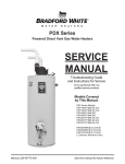
OPTION 1: Install a 125 PSI Pressure Relief (only) valve in the cold
water supply line. Make sure that the discharge of this valve is directed
to a drain to prevent water damage and it is protected from freezing,
OR
OPTION 2: Install an expansion tank on the cold water supply line. For
every 50 U.S. gallons of stored water, the expansion tank must have a
minimum capacity of 1.5 U.S. gallons.
Pressure Build-Up (Thermal Expansion)
Temperature Relief: The T&P valve will discharge varying amounts of
water, but typically more than you would experience from thermal expansion. Check the temperature in relation to the setting on the thermostat
dial. A malfunctioning thermostat could cause the water to get too hot.
During the heating cycle of the water heater, the water expands creating
a pressure build-up in the plumbing system. If the pressure exceeds 150
PSI, water will come out of the valve. This is a normal safety function of
the T&P valve. The water supply meter may have a check valve or back
flow preventer inside. This can increase the possibility of pressure buildup. Causes of discharge can be thermal expansion, excess system pres-
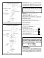
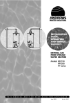
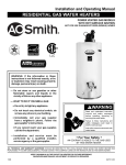
Cold in
OPTION 2
Hot out
OPTION 1
Floor drain
Drain pan*
Floor drain
Cold water inlet
Hot water outlet
Anode(s)
Temperature and pressure (T&P) relief valve*
Alternate location of T&P relief valve*
Thermostat with High-limit switch
Element
Access door - not illustrated
Thermostat
Drain valve
Water supply to meter
Water supply to water heater
Water meter with backflow preventer
Overflow
Pressure relief valve
Expansion tank
Pipe Insulation (mandatory if supplied with
heater)
*Items to be supplied by installer.
Options 1 and 2 show the location of pressure relief
and/or expansion tank if a check valve or pressure
reducing valve is in the cold water supply to the
house. Use option 1 or 2 as convenient. If a pressure
relief valve is used (OPTION 1) select one with a setting 25 psi below the relief valve rating used on the
heater.
Hot out
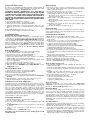
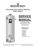
SPACESAVER™ MODELS
(SIDE OUTLET) ONLY
NOTE TO INSTALLERS:
A bent tube (as shown) is
installed for the hot water
outlet on side outlet water
heaters to ensure a maximum of hot water supply.
This fitting must be aligned
properly. The 'line' on the
fitting must be oriented
pointing up. When in correct
position, the hot water is
drawn from the highest
point in the tank.
1.
2.
3.
4.
4a.
5.
6.
7.
8.
9.
10.
11.
12.
13.
14.
15.
16.
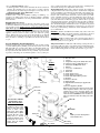
Cold in
Drain pan*
Refer to pressure relief/expansion
tank schematic above.
Tee fitting
Floor Drain
5
Drain valve*
~ Certificate of Warranty ~
Warranty Code:
See Rating Label Serial Number prefix for
Warranty Code. Reduced warranty period
applies to Newfoundland.
Standard Warranty Years:
Reduced Warranty Years:
P R S T U V W
3 5 6 7 8 9 10
2 3 3 5 5 5 5
Y
12
7
For its GSW and John Wood water heaters and storage boosters ("Unit"), GSW Water Heating ("GSW") warrants that, upon
receipt of a properly verified Warranty claim within the Warranty Period, it will, at its election, repair or replace: units which leak or parts which are defective
in material or workmanship, subject to the terms and conditions set forth in this certificate. GSW will not assume any expense or liability for unauthorized
returns, nor repairs made by a person who has not been authorized by GSW or one of its authorized dealers. GSW Units/parts must be replaced with GSW or
John Wood products to be eligible for Warranty. This Warranty is available to the original owner of a Unit installed within the boundaries of continental United
States, of Canada, or their territories. Consumers must retain point-of-sale proof of purchase to validate warranty entitlement. This Warranty does not
cover components not manufactured by GSW, such as oil burners, which carry the warranty given by the manufacturer thereof, copy of which warranty GSW
will make available, to the extent supplied by the manufacturer, without recourse to GSW.
THERE ARE NO WARRANTIES WHICH EXTEND BEYOND THE DESCRIPTION ON THE FACE HEREOF. THIS EXPRESS
WARRANTY IS, WHERE PERMITTED BY LAW, IN LIEU OF AND EXCLUDES AND REPLACES ALL OTHER CONDITIONS,
WARRANTIES, GUARANTEES, REPRESENTATIONS, OBLIGATIONS OR LIABILITIES OF GSW OF ANY NATURE OR KIND,
EXPRESS OR IMPLIED, HOWEVER ARISING (WHETHER BY CONTRACT, CONDUCT, STATEMENT, STATUTE, NEGLIGENCE, PRINCIPLES OF MANUFACTURER'S LIABILITY, OPERATION OF LAW OR OTHERWISE) WITH RESPECT TO THE
UNIT OR ITS FITNESS FOR A PARTICULAR PURPOSE, MERCHANTABILITY, INSTALLATION, OPERATION, REPAIR OR
REPLACEMENT. GSW EXPRESSLY DISCLAIMS ANY AND ALL IMPLIED WARRANTIES. IN NO EVENT WILL GSW'S LIABILITIES EXCEED THE COST OF THE DEFECTIVE PART(S) OR UNIT. GSW WILL NOT PAY FOR ANY TRANSPORTATION,
LABOUR, INSTALLATION, OR OTHER INCIDENTAL COSTS ASSOCIATED WITH THE REPAIR OR REPLACEMENT OF A
DEFECTIVE PART OR UNIT.
This warranty and GSW's obligations shall be construed and determined in accordance with the laws of both the Province of Ontario, and of Canada in force
therein. This Warranty does not affect specific legal rights of a consumer under applicable law, except to the extent that such rights may be waived or replaced,
and the provisions hereof are deemed to be amended to the extent necessary. The unenforceability of any provision, in whole or in part, of this Certificate shall
not affect the remaining provisions. Any and all repair and/or replacement of part(s) or Unit are the sole and exclusive remedy available against GSW.
LIABILITY OF GSW COVERED BY THIS WARRANTY IS CONDITIONAL UPON THE FOLLOWING:
1.
2.
3.
4.
5.
6.
The Unit shall be installed in accordance with all manufacturers' instructions, all applicable equipment and building codes, ordinances and regulations (hereinafter referred to as the "standards").
The Unit must not be installed where water damage can result from a
leak, while provision(s) shall be made for directing any water escaping
from the Unit, to a properly operating drainpipe. As all units of this type
may eventually leak, you must protect against any potential water damage. GSW accepts no responsibility for such damage, nor any incidental
or consequential loss, nor damage(s) related thereto, suffered by the
owner of the Unit nor by any third party.
The Unit shall not be installed where it will be exposed to adverse or
unusual environmental or corrosive conditions. No warranty extends, for
example, and without limitation of the foregoing, to Units exposed to:
salts; chemicals; exhausts; pollutants or contaminants. Further, no warranty extends to Units affected by fire, freezing or flood, "Acts of God",
or any other contingency beyond the control of GSW.
The Unit shall be equipped with a properly operating temperature and
pressure relief valve as specified by GSW and applicable standards. The
Unit shall be operated at temperatures not exceeding the maximum setting of the thermostat and/or high limit control provided by GSW, and at
water pressures not exceeding the pressure reading stated on the Unit.
The Unit must be carefully inspected, maintained, and operated in accordance with the manufacturer's instructions. No warranty extends, for
example, and without limitation of the foregoing, to any Unit operated:
without the tank being completely filled with water; without an operating
anode; with levels of sediment or lime precipitate which cause failure; in
connection to any attachment(s), energy saving device(s), or other means
of heating, except as approved by GSW for the Unit; other than with
potable water without any additives such as salts, chlorine or chemicals,
except those added for the sole purpose of rendering the water fit for
domestic use.
All repairs must be made by a competent and qualified person who is certified, by GSW or one of its authorized dealers, to work on the Unit, using
factory approved replacement parts, and the Unit shall not be otherwise
modified, altered or improperly repaired.
7.
8.
9.
6
A properly documented claim shall be received by GSW or one of its
authorized dealers, or point of purchase, within the following Warranty
Period, except as provided otherwise below*:
a) for any defective part, within one (1) year; or
b) for any Unit that develops leaks in the inner tank due to rust, corrosion
or other chemical reactions caused by the potable domestic water supplied to your home, within the period of time shown in table at the top of
this page.
* Residential units installed and used in a commercial application carry a
warranty period of one (1) year from date of installation; and,
Any repair or replacement of any part, tank, or Unit under this Warranty
will not extend the Warranty Period beyond that calculated from the date
of first installation of the original Unit. The date of first installation will
be deemed to be the later of the date indicated by the Unit's serial number, or if supplied with the Warranty claim, the sales receipt, or installer's
receipt.
A claim under this Warranty must include the model and serial number of
the Unit, proof of date on which the Unit was first installed, and the identity of the defective part(s) for which a claim is being made and be submitted within 15 days following discovery of the defect(s), by personal
delivery to a GSW authorized dealer, point of purchase, or GSW itself at:
GSW Water Heating
GSW Water Heating is a division of GSW Water Products Inc.
599 Hill Street West
Fergus, ON Canada N1M 2X1
Should you have questions, please call our Technical Support Line at 1888-479-8324.
If requested by GSW, information relating to the purchase, transportation,
operation and installation of the Unit must be supplied. The defective
part(s) or Unit, with all components properly and securely packed, shall
be returned transportation pre-paid, to the address designated by GSW in
the written request. All claims are subject to validation by GSW.