1
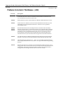
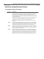
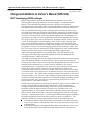
Restarts for autonumbers that do not restart in each
chapter.
figure bi level 1, reset
table_big level 1, reset
chap_big level 1, reset
app_big level 1, reset
figure_ap level 1, reset
table_ap level 1, reset
figure level 1, reset
table level 1, reset
these restarts must be in the header frame of chapter 1.
a:ebx, l 1 resetA
a:obx:l 1, resetA
a:bigbx level 1 resetA
a:ftr level 1 resetA
c:ebx, l 1 reset1
c:obx:l 1, reset1
c:bigbx level 1 reset1
c:ftr level 1 reset1
Reminders for autonumbers that need to be restarted
manually (first instance will always be 4)
let_in level 1: A. B. C.
letter level 1:A.B.C.
num level 1: 1. 2. 3.
num_in level 1: 1. 2. 3.
rom_in level 1: I. II. III.
roman level 1: I. II. III.
steps level 1: 1. 2. 3.
December 15, 1997
GFK-1314F
IMPORTANT PRODUCT INFORMATION
READ THIS INFORMATION FIRST
Product:
IC697 Factory LAN Ethernet Interface (Type 2)
IC697CMM742-FE
IC697CMM742-EE
Firmware Version 2.60
This is release 2.60 of the IC697 Ethernet Interface (Type 2). This module provides
network communications using the SRTP (Service Request Transfer Protocol) over
standard TCP/IP (Transmission Control Protocol and Internet Protocol) on an Ethernet
LAN (Local Area Network). The Ethernet Interface supports communications between
IC697 PLCs and/or IC693 PLCs equipped with TCP/IP Ethernet Interfaces. The Ethernet
Interface can also communicate with MS-DOS Programming Software for IC697 TCP/IP,
Windows Programming Software, and applications which use the TCP/IP Host
Communication Toolkit software.
Features and benefits for this module include:
H
Higher performance compared to IC697CMM741—2 to 4 times higher throughput
for data transfers between PLCs with identical Channel setups. Up to 32
simultaneous network connections—twice the number supported by
IC697CMM741.
H
Unlike the IC697CMM741, configuration of the Ethernet Interface is fully supported
within CPU configuration. Centralized IP network configuration management is
also supported via standard BOOTP protocol. Centralized Domain Name
management is supported via standard DNS protocol.
H
Three alternative Ethernet network ports are available on the IC697CMM742
Interface. Two of the network ports, the 10BaseT (twisted pair) and the 10Base2
(thin wire), require no external transceiver. In addition, a standard AUI port is
available for use with an external user-supplied transceiver. Only one of the three
network ports may be used at a time.
H
Support for Ethernet Global Data, a means by which one device, referred to as a
producer, can share a portion of its internal memory with one or more other
EGD-capable devices, referred to as consumers, at a regularly scheduled periodic rate.
An in-depth description of this feature is available through Windows Programming
Software Online Help (Version 2.00 or later). This feature requires IC697 CPU
Release 7.20 or later as well as Windows Programming Software Version 2.00 or later.
Release 2.60 provides a new feature, multiplegateways. Note that Windows
Programming Software Version 2.10 is required to use this new feature. See New
Software Features for other improvements included in this release.
Important Product Information: IC697 Factory LAN Ethernet Interface (Type 2)
2
GFK-1314F
December 15, 1997
Functional Compatibility
The IC697CMM742 Interface is compatible with the following products:
H
IC697 CPU models 781, 782, 914, 915, 924, and 925 loaded with firmware versions
6.00 or higher.
Limited Server-mode only operation is possible with older CPU models (731/2,771/2:
4.12; 780: 4.60). For some features, more recent CPU releases are required:
h
h
h
H
H
H
H
H
H
H
H
H
H
H
H
Ethernet Global Data:
Name Resolution:
SNTP timestamping of EGD:
Release 7.20 or higher
Release 7.00 or higher
Release 7.80 or higher (Release 7.50 or higher
for Redundancy systems)
IC697 Ethernet Interface IC697CMM741 loaded with TCP/IP software IC651ENS042.
IC693 Ethernet Interface IC693CMM321
MS-DOS Programming Software version 6.02 or higher (required to configure the
Ethernet Interface). For some features, Windows Programming Software is required
(see below).
Windows Programming Software Version 1.00 or higher. For some features, higher
versions are required:
h
h
h
h
Ethernet Global Data:
Version 2.00 or higher
SNTP timestamping of EGD:
Version 2.10 or higher
Name Resolution :
Version 2.00 or higher
Multiple Gateways:
Version 2.10 or higher
Host Communications Toolkit (HCT) software products listed below.*
Toolkit for Windows NT/95 C/C++ Applications (IC641SWP058)
Toolkit for Windows 3.xx C/C++ Applications (IC641SWP052)
Toolkit for HP-UX C Applications (IC641SWP054)
Toolkit for DEC VAX/VMS C Applications (IC641SWP053)
Toolkit for DEC Alpha AXP/VMS C/C++ Applications (IC641SWP057)
Host Communication Drivers for Windows NT/95 (IC641SWP080, IC641SWP081)
Host Communication Drivers for Windows (IC641SWP050, IC641SWP051)
*Some versions of HCT do not support the ‘Send Information Report’ COMMREQ or Ethernet Global Data. Please refer to
the appropriate HCT IPI document for more information.
Hardware Identification
EX7A1: 44A737150-G01 R07
Field Update Kit
44A739337-G03
Data Sheet
GFK-1309D
User Manuals
GFK-1246B, TCP/IP Ethernet Communications for the IC697 PLC (Type 2) User’s Manual
GFK-1186D, TCP/IP Ethernet Communications for the IC697 PLC Station Manager Manual
3
Important Product Information: IC697 Factory LAN Ethernet Interface (Type 2)
GFK-1314F
December 15, 1997
Operational Notes
Network Bandwidth Utilization
Due to its performance potential, the IC697CMM742 Interface can present a heavy load
on the network segment at its maximum operating capacity. Both Ethernet Global Data
and Channel operation can contribute to an extremely high rate of network traffic when
even a few such modules are involved. The potentially high network bandwidth
utilization can cause a higher-than-normal rate of network collisions which may cause
timeouts on data transfers. By configuring transfer timing to no more than you need,
you can minimize such problems.
For Ethernet Global Data operation, it is strongly recommended that caution be taken
when defining exchange parameters. In particular, period values should be set to the
required rates for your particular application instead of ‘as fast as possible’ rates.
For Channel operation, it is strongly recommended that caution be taken when using
multiple connections operating in an ‘as fast as possible’ mode. Tests conducted at the
factory showed that 32 simultaneous Channels transferring 2 Kilobytes of data per
Channel between two IC697CMM742’s can use up as much as 18% of the total network
bandwidth when the Channels are all configured to run ‘as fast as possible’ using 91x or
92x CPUs. Network administrators consider 30% the threshold of Ethernet network
overload. If your application requires many simultaneous network connections between
IC697CMM742 Interfaces, it is recommended that the ‘minimum interval between host
accesses’, ‘read period’, and ‘write period’ used in COMMREQs be set to the required rate
for your particular application instead of ‘as fast as possible’. This will reduce the risk of
overloading the network with traffic to and from the IC697CMM742 Interface.
CPU Performance Limitation
Again, due to its performance potential, the IC697CMM742 Interface can present a
heavy load on the CPU at its maximum operating capacity. It is strongly recommended
that caution be taken when using multiple connections operating in an “as fast as
possible’”mode especially when a model 781 or 782 CPU is used. The COMMREQ Status
Word (CRS Word) may occasionally become FE07 or FE87, which means service requests
are made to the CPU faster than the CPU can process them. Although communications
will proceed to the next repetition even when this is encountered, data transfer for the
current repetition of this connection would have failed to complete.
To avoid this situation, configure the “minimum interval between host accesses”, “read period”,
or “write period” to a larger value so the CPU has enough time to process all service
requests.
Also, issuing a large number of COMMREQs to one Interface in one sweep may result in
temporary resource exhaustion within the CPU, the Ethernet Interface, or both. If this
occurs, the PLC logs a fault in the PLC fault table with fault group of “Option Module
Software Failure” and error code equal 2 indicating that the COMMREQ frequency is too
high. When this occurs, the ”FT” output of the COMMREQ function block will also be
set. It is recommended to use logic that staggers the execution of COMMREQs across
multiple sweeps so that a limited number of COMMREQs (typically 8 or less) are sent to
a given board in each sweep. In addition, the FT output parameter should be checked
for errors. If the FT output is set (meaning an error has been detected), the CommReq
can be re-issued by the application logic.
Important Product Information: IC697 Factory LAN Ethernet Interface (Type 2)
4
GFK-1314F
December 15, 1997
Use of Windows Programming Software “Store” Function
When performing a Store to PLC operation from Windows Programming Software
Version 2.0 to a PLC system that contains an IC697CMM742 Interface. we make the
following important operational recommendation regarding the Hardware Config
components that appear within the Folder tab:
Every Hardware Config component that appears in the Store dialog must always
be selected when performing a Store operation.
Failure to follow this recommendation may result in unexpected operation of Ethernet
Global Data and Name Resolution features. (Note: this guideline does not apply to Store
operations that include only Global Vars and/or Resource, which are not Hardware
Config components.)
Channel Data Transfer with One Repetition can
Exhaust TCP Connections
Because tearing down a TCP connection is time consuming, it is possible that
programming your ladder in a certain way can quickly exhaust all available TCP
connections. This can be avoided by programming your COMMREQs in a slightly
different way.
Your ladder can benefit from this reprogramming if:
H
The number of repetitions (word 9 in an Establish Read Channel or Establish Write
Channel COMMREQ) is set to one (1) and a new COMMREQ is issued immediately
upon completion of the prior one.
H
H
Each successive COMMREQ is directed to the same target device (same IP address).
Each successive COMMREQ is directed to the same channel number.
To avoid TCP connection exhaustion you should set the number of repetitions
(COMMREQ word 9) to two (2) and set the read/write period (COMMREQ words 10
and 11) to be very large, such as 60 seconds. With these parameters you can issue the
first COMMREQ, wait for the COMMREQ Status (CRS) word to turn to one (1), then
issue the next COMMREQ, wait for the CRS word to turn to one, etc., and there will not
be TCP connection exhaustion problems. Interrupting an active channel allows the reuse
of an existing TCP connection, while a repetition count of one starts the time-consuming
TCP connection teardown immediately upon completion of the first transfer. You will
also achieve faster response, as a new connection need not be established for each
transfer.
AUI Cable Removal
Power to the PLC must be turned off whenever the transceiver cable (AUI cable) is
connected or disconnected at the IC697CMM742 Interface AUI port or at the transceiver.
SQE Enable
If the AUI network port is used, the IC697CMM742 Interface requires that the SQE test
be enabled on the external transceiver connecting it to the Ethernet LAN. Make sure
your transceiver has SQE enabled. Otherwise, the Ethernet Interface will not go online
and will log a “LAN Severe Network Problem; Attempting Recovery” fault.
5
Important Product Information: IC697 Factory LAN Ethernet Interface (Type 2)
GFK-1314F
December 15, 1997
Ethernet Interface PLC Installation Restrictions
The IC697CMM742 Interface may not be used in an IC697 PLC expansion rack. The
Ethernet Interface will not function properly if placed there.
There may be no more than four (4) LAN Interfaces in a single PLC. This limit applies to
the total number of IC697CMM721, IC697CMM731, IC697CMM741, IC697BEM741, and
IC697CMM742 boards in the PLC.
PLC Power Supply Requirements
If the AUI network port is used, the IC697CMM742 Interface requires that the PLC
include a power supply which supplies 12Vdc (IC697PWR711,-724, or -748). (note: if an
externally powered transceiver is used on the AUI network port, 12Vdc is not required
but an erroneous ‘blown fuse’ fault will appear in the CPU fault table.)
Special Notes on Release 6 CPUs
When your ladder program accesses %P and %L memories through COMMREQs, and a
Release 6.00 CPU is used on the server PLC, the COMMREQ Status Word (CRS Word)
may occasionally return F405. If this occurs, temporary relief may be obtained by cycling
power on the server PLC. Permanent relief requires a CPU firmware upgrade to 6.02 or
greater.
Some PLC Fault Table Entries are Imprecise
In the PLC Fault Table display of the IC641 Programming software, the following
messages may not provide a meaningful description of the problem for the Ethernet
Interface:
H
H
H
H
“LAN PROM/software mismatch; running soft Sw util”
“LAN system-software fault; resuming”
“LAN Severe Network Problem; Attempting Recovery”
“Module software corrupted; requesting reload”
Should you see these messages, select the message and enter F10 (ZOOM) or CTRL+F
to display the error codes associated with the message. Then refer to GFK-1186D,
Appendix B: “Exception Log Event Description” for an accurate explanation of the error
codes.
(For IC697CMM742-EE only) 802.3 Specifications
The IEEE 802.3 specification for isolation voltage of the 10BaseT network port is 1500 Vac
and 2250 Vdc. The measured value for the IC697CMM742-EE is 1000 Vac and 1200 Vdc.
Important Product Information: IC697 Factory LAN Ethernet Interface (Type 2)
6
GFK-1314F
December 15, 1997
New Software Features
Multiple Gateways
Multiple Gateways support communications between PLCs on different subnets
interconnected by gateways (sometimes called routers). An Ethernet Interface with the
Multiple Gateways feature has the ability to route packets not only through a single
default gateway, but also through additional gateways located on the local subnet. This
feature requires Windows Programming Software Version 2.10 or later. A more detailed
description of Multiple Gateways is available through the Windows Programming
Software Online Help.
SNTP Timestamping of Ethernet Global Data Exchanges
This release of the IC697CMM742 Ethernet Interface can provide SNTP-supplied time
value in the timestamps of Ethernet Global Data exchanges. A central SNTP server can
be used to supply time to listening stations periodically, permitting participating stations
to maintain synchronized clocks, thus providing consistency of Ethernet Global Data
timestamps across participating stations. This feature requires IC697 CPU Release 7.80
or later (Release 7.50 or later for Redundancy systems) as well as Windows
Programming Software Version 2.10 or later. A detailed description of this feature can be
found in Changes and Additions to the User’s Manual, later in this document.
Increased LLC Transmit Queue Length
The default length of the LLC transmit ring has been increased from 23 (8) frames to 27
(128) frames. Log Event c, entry 2 = 10f may have been witnessed during extremely
heavy traffic conditions on the Local Area Network when the length was 8.
Increased Station Manager Command Recall
The Station Manager now maintains a list of the 10 most recently issued commands. The
keystroke CTRL+R can be repeated to scroll through the list of previous commands.
The command list is not saved across module restarts or power cycles.
7
Important Product Information: IC697 Factory LAN Ethernet Interface (Type 2)
GFK-1314F
December 15, 1997
Problems Corrected in This Release (2.60)
ÁÁÁÁÁÁÁÁÁÁÁÁÁÁÁÁÁÁÁÁÁÁÁÁÁÁÁÁÁÁÁ
ÁÁÁÁ
ÁÁ
ÁÁÁÁÁÁÁÁÁÁÁÁÁÁÁÁÁÁÁÁÁÁÁÁÁ
ÁÁÁÁÁÁÁÁÁÁÁÁÁÁÁÁÁÁÁÁÁÁÁÁÁÁÁÁÁÁÁ
ÁÁÁÁÁÁÁÁÁÁÁÁÁÁÁÁÁÁÁÁÁÁÁÁÁ
ÁÁÁÁÁÁ
ÁÁÁÁÁÁÁÁÁÁÁÁÁÁÁÁÁÁÁÁÁÁÁÁÁÁÁÁÁÁÁ
ÁÁÁÁ
ÁÁ
ÁÁÁÁÁÁÁÁÁÁÁÁÁÁÁÁÁÁÁÁÁÁÁÁÁ
ÁÁÁÁÁÁÁÁÁÁÁÁÁÁÁÁÁÁÁÁÁÁÁÁÁÁÁÁÁÁÁ
ÁÁÁÁÁÁÁÁÁÁÁÁÁÁÁÁÁÁÁÁÁÁÁÁÁ
ÁÁÁÁÁÁ
ÁÁÁÁ
ÁÁ
ÁÁÁÁÁÁÁÁÁÁÁÁÁÁÁÁÁÁÁÁÁÁÁÁÁ
ÁÁÁÁ
ÁÁ
ÁÁÁÁÁÁÁÁÁÁÁÁÁÁÁÁÁÁÁÁÁÁÁÁÁ
ÁÁÁÁ
ÁÁÁÁÁÁÁÁÁÁÁÁÁÁÁÁÁÁÁÁÁÁÁÁÁ
ÁÁ
ÁÁÁÁÁÁÁÁÁÁÁÁÁÁÁÁÁÁÁÁÁÁÁÁÁÁÁÁÁÁÁ
ÁÁÁÁÁÁÁÁÁÁÁÁÁÁÁÁÁÁÁÁÁÁÁÁÁ
ÁÁÁÁÁÁ
ÁÁ
ÁÁÁÁÁ
ÁÁÁÁÁÁÁÁÁÁÁÁÁÁÁÁÁÁÁÁÁÁÁÁÁÁ
ÁÁÁÁÁÁÁÁÁÁÁÁÁÁÁÁÁÁÁÁÁÁÁÁÁÁÁÁÁÁÁ
ÁÁÁÁ
ÁÁ
ÁÁÁÁÁÁÁÁÁÁÁÁÁÁÁÁÁÁÁÁÁÁÁÁÁ
ÁÁÁÁÁÁÁÁÁÁÁÁÁÁÁÁÁÁÁÁÁÁÁÁÁÁÁÁÁÁÁ
ÁÁÁÁÁÁÁÁÁÁÁÁÁÁÁÁÁÁÁÁÁÁÁÁÁÁÁÁÁÁÁ
ÁÁÁÁ
ÁÁ
ÁÁÁÁÁÁÁÁÁÁÁÁÁÁÁÁÁÁÁÁÁÁÁÁÁ
ÁÁÁÁ
ÁÁ
ÁÁÁÁÁÁÁÁÁÁÁÁÁÁÁÁÁÁÁÁÁÁÁÁÁ
ÁÁÁÁ
ÁÁ
ÁÁÁÁÁÁÁÁÁÁÁÁÁÁÁÁÁÁÁÁÁÁÁÁÁ
ÁÁÁÁÁÁÁÁÁÁÁÁÁÁÁÁÁÁÁÁÁÁÁÁÁÁÁÁÁÁÁ
ID Code
Description
CR60889
The limit of 16 ARP table entries can result in unnecessary transmission delays and network traffic when a PLC needs to communicate with more than 16 other hosts. The
size of the ARP cache has been increased to 256.
CR62254
Memory buffers may be lost when Channels are arbitrarily re-tasked while they are active.
CR63505
Under certain rare conditions, a frame received from the Ethernet network may not be
immediately processed by the Ethernet Interface. All frames are now queued for
immediateprocessing.
CR62481
CR62555
CR62990
Name Resolution information, the Adapter Name list, the Aliases name list and the
Interface’s Adapter Name, was retained even when a new configuration that contained
no Name Resolution information was stored. Now that authoritative Name Resolution
information is always obtained from the PLC CPU, the CHMYNAME and CHNAMETBL
Station Manager commands have been disabled. This means that Name Resolution
information must always be entered at the PLC Programmer and stored into the PLC.
CR61481
PLC fault table entries for Ethernet Global Data fault conditions have been made more
descriptive. The entries are described in Table B-2 within Appendix B of GFK-1186D.
CR62846
The Station Manager commands STAT G and XCHANGE should use the dotted-decimal
form to display the EGD Producer ID, similar to its usage in the Windows Programming
Software.
CR63212
If the network name server cannot be accessed when EGD production is begun, any exchange which relies on name resolution is not activated, even if the name server becomes
availablelater. In this release, the name resolution continues to be retried and the exchange production will begin when the name is resolved successfully.
Important Product Information: IC697 Factory LAN Ethernet Interface (Type 2)
8
GFK-1314F
December 15, 1997
Restrictions and Significant Open Problems
Open Problems in Release 2.60 Firmware
ÁÁÁÁÁÁÁÁÁÁÁÁÁÁÁÁÁÁÁÁÁÁÁÁÁÁÁÁÁÁÁ
ÁÁÁÁ
ÁÁ
ÁÁÁÁÁÁÁÁÁÁÁÁÁÁÁÁÁÁÁÁÁÁÁÁÁ
ÁÁÁÁ
ÁÁ
ÁÁÁÁÁÁÁÁÁÁÁÁÁÁÁÁÁÁÁÁÁÁÁÁÁ
ÁÁÁÁÁÁÁÁÁÁÁÁÁÁÁÁÁÁÁÁÁÁÁÁÁÁÁÁÁÁÁ
ÁÁÁÁ
ÁÁ
ÁÁÁÁÁÁÁÁÁÁÁÁÁÁÁÁÁÁÁÁÁÁÁÁÁ
ÁÁÁÁ
ÁÁ
ÁÁÁÁÁÁÁÁÁÁÁÁÁÁÁÁÁÁÁÁÁÁÁÁÁ
ÁÁÁÁÁÁ
ÁÁÁÁÁÁÁÁÁÁÁÁÁÁÁÁÁÁÁÁÁÁÁÁÁ
ÁÁ
ÁÁÁÁ
ÁÁÁÁÁÁÁÁÁÁÁÁÁÁÁÁÁÁÁÁÁÁÁÁÁ
ÁÁÁÁ
ÁÁ
ÁÁÁÁÁÁÁÁÁÁÁÁÁÁÁÁÁÁÁÁÁÁÁÁÁ
ÁÁÁÁÁÁÁÁÁÁÁÁÁÁÁÁÁÁÁÁÁÁÁÁÁÁÁÁÁÁÁ
ÁÁÁÁÁÁ
ÁÁÁÁÁÁÁÁÁÁÁÁÁÁÁÁÁÁÁÁÁÁÁÁÁ
ÁÁÁÁÁÁÁÁÁÁÁÁÁÁÁÁÁÁÁÁÁÁÁÁÁÁÁÁÁÁÁ
ÁÁÁÁÁÁÁÁÁÁÁÁÁÁÁÁÁÁÁÁÁÁÁÁÁ
ÁÁÁÁ
ÁÁ
ÁÁÁÁ
ÁÁ
ÁÁÁÁÁÁÁÁÁÁÁÁÁÁÁÁÁÁÁÁÁÁÁÁÁ
ÁÁÁÁÁÁÁÁÁÁÁÁÁÁÁÁÁÁÁÁÁÁÁÁÁÁÁÁÁÁÁ
ÁÁÁÁÁÁÁÁÁÁÁÁÁÁÁÁÁÁÁÁÁÁÁÁÁ
ÁÁÁÁ
ÁÁ
ÁÁÁÁ
ÁÁ
ÁÁÁÁÁÁÁÁÁÁÁÁÁÁÁÁÁÁÁÁÁÁÁÁÁ
ÁÁÁÁ
ÁÁ
ÁÁÁÁÁÁÁÁÁÁÁÁÁÁÁÁÁÁÁÁÁÁÁÁÁ
ÁÁ
ÁÁÁÁ
ÁÁÁÁÁÁÁÁÁÁÁÁÁÁÁÁÁÁÁÁÁÁÁÁÁ
ÁÁÁÁÁÁÁÁÁÁÁÁÁÁÁÁÁÁÁÁÁÁÁÁÁÁÁÁÁÁÁ
ÁÁÁÁÁÁÁÁÁÁÁÁÁÁÁÁÁÁÁÁÁÁÁÁÁ
ÁÁÁÁ
ÁÁ
ÁÁÁÁÁÁÁÁÁÁÁÁÁÁÁÁÁÁÁÁÁÁÁÁÁÁÁÁÁÁÁ
ID Code
Description
CR54556
The IC697CMM742 Interface can not communicate with the local PLC CPU when a PLC
load or a store operation is in progress. A PLC load or store operation (via MS-DOS Programmer WSI, Serial, and/or Ethernet or Windows Programmer either serial or
Ethernet) has priority over all other communications. During a PLC load or store operation, it is possible for channels or server connections to experience time out errors, which
may lead to disconnections.
Possible exception log entries include log event 8, entry 2 = 8, 38, or 40. Whenever these
backplane errors are logged, there are likely to also be additional exception logs for
terminated TCP connections and SRTP Server and Channel API errors.
Application programs should always be written to detect and recover from time out
conditions.
CR63808
Under very heavy Channel load conditions, LAN system software faults are intermittently
reported. The reported exception log entry is log event 8, entry 2 = 39, entry 3 = fff5. This
has been observed in an application with 32 Write Channels of 1024 bytes each, updating
and “retasking” as quickly as possible. Channel operation continues without errors.
CR64052
While a local Station Manager “TRACE LZ” troubleshooting command is in effect at an
Ethernet Interface, do not issue Station Manager “REM <node> TEST” commands to it
from a remote Interface. Doing so can cause errant behavior, including module lockup
and loss-of-module in the PLC fault table.
CR64699
Storing Hardware Configuration that contains new or changed values for the Ethernet
Interface’s configuration results in exception event 11/5 and corresponding PLC Fault
Table entry, “Local request to send was rejected; discarded request”. This fault affects
only DDP2 Name Resolution operation, with the result that the existence of duplicate
DDP2 names on the network is detected at the time that communication to one of the
duplicate-name stations is attempted, rather than at the time of Configuration store.
9
Important Product Information: IC697 Factory LAN Ethernet Interface (Type 2)
GFK-1314F
December 15, 1997
Changes and Additions to the User’s Manual (GFK-1246)
SNTP Timestamping of EGD exchanges
Release 2.50 (and later) of the IC697CMM742 Ethernet Interface can provide
SNTP-supplied value in the timestamps of EGD exchanges. To enable this feature,
Release 7.01 of MS-DOS Programming Software or Version 2.10 of Windows
Programming Software must be used to configure the Ethernet Interface, and IC697 PLC
CPU Release 7.80 or later (Release 7.50 or later for Redundancy systems) must be used.
Each consumed EGD exchange contains a timestamp that indicates the time that the
associated data sample was transferred to the Ethernet Interface by the producing CPU
for transmission. For Ethernet Interface Release 2.00, the timestamp was set according
to the PLC CPU’s local clock. For Ethernet Interface Release 2.50, the timestamp can
optionally be set using a clock value supplied by a central user-supplied Simple Network
Time Protocol (SNTP) time server on the network. By default, the PLC CPU’s local clock
is used. To enable SNTP clock timestamping, select “SNTP” for the “Network Time
Sync” field in the Ethernet Interface configuration. Doing so will cause the Ethernet
Interface to listen for a broadcast clock value from an SNTP server. The clock value will
be supplied to the PLC CPU for timestamping produced EGD exchanges. NOTE: the
PLC CPU’s local clock is not affected by the SNTP-supplied clock value, and the Ethernet
Interface module’s local clock is synchronized to the SNTP-supplied value.
SNTP timestamping is enabled on a per module basis. The clock source for EGD
exchanges produced through a particular Ethernet Interface is determined by the
“Network Time Sync” field for that module.
Any SNTP or NTP compliant server that supports broadcast/multicast operation may be
used. The Ethernet Interface will synchronize to a server’s time after receiving two
broadcast clock values within a 150 second period. The Ethernet Interface will store and
maintain clock information for up to three servers in addition to the currently
synchronized server. If a broadcast clock value is not received from the current server
within 150 seconds, it will be considered “lost” and the Ethernet Interface will
synchronize with another server if one is available. Also, if at any time two clock values
are received from a lower-stratum server, the Ethernet Interface will synchronize to the
new server’s time. The “SNTP” station manager command may be used to view server
status information. The “CHSNTP” station manager command may be used to override
the Ethernet Interface module’s automatic server selection strategy and identify specific
server(s) to be used. See “TCP/IP Ethernet Communications for the IC697 PLC Station
Manager Manual “ GFK-1186D for details.
If SNTP time synchronization is selected and no broadcast value is received within a 150
second period, the Ethernet Interface determines that no SNTP-supplied time is
currently available for EGD timestamping. In this case, an entry is made in the PLC
Fault Table and in the Ethernet Interface exception log. (The fault text is “User
Application Fault” or “LAN system-software fault; resuming”, the log event code is “29”.)
In this case, the Status word within a consumed exchange will indicate new data with
the value “3” (instead of the value “1”), indicating that SNTP timestamping is enabled in
the producing Ethernet Interface but that currently no server is available to it. The
timestamp within the exchange will be based on one of two possible time bases:
H
H
if the Ethernet Interface has not been able to synchronize to any SNTP server since
its power-up/restart, it will use the PLC CPU’s local clock value at power-up/restart
as the time base.
if the Ethernet Interface has at some point been able to synchronize to a server, it will
use the most recently received SNTP clock value from that server as the time base.
Important Product Information: IC697 Factory LAN Ethernet Interface (Type 2)
10
GFK-1314F
December 15, 1997
In either case, the clock on the Ethernet Interface continues running based on the time
base value last supplied. The Ethernet Interface also continues to supply the time value
to the CPU for inclusion in produced exchanges. In addition, it continues to monitor
SNTP messages, and will become synchronized when possible.
One additional exchange status value is possible when STNP timestamping is in use.
The value is described below:
ÁÁÁÁÁÁÁÁÁÁÁÁ
ÁÁÁÁÁÁÁÁÁÁÁÁÁÁÁÁÁÁÁ
ÁÁÁÁÁÁÁÁÁÁÁÁ
ÁÁÁÁÁÁÁÁÁÁÁÁÁÁÁÁÁÁÁ
ÁÁÁÁÁÁÁÁÁÁÁÁ
ÁÁÁÁÁÁÁÁÁÁÁÁÁÁÁÁÁÁÁ
ÁÁÁÁÁÁÁÁÁÁÁÁ
ÁÁÁÁÁÁÁÁÁÁÁÁÁÁÁÁÁÁÁ
ÁÁÁÁÁÁÁÁÁÁÁÁ
ÁÁÁÁÁÁÁÁÁÁÁÁÁÁÁÁÁÁÁ
ÁÁÁÁÁÁÁÁÁÁÁÁ
ÁÁÁÁÁÁÁÁÁÁÁÁÁÁÁÁÁÁÁ
ÁÁÁÁÁÁÁÁÁÁÁÁ
ÁÁÁÁÁÁÁÁÁÁÁÁÁÁÁÁÁÁÁ
ÁÁÁÁÁÁÁÁÁÁÁÁ
ÁÁÁÁÁÁÁÁÁÁÁÁÁÁÁÁÁÁÁ
STATUS VALUE
DESCRIPTION
NEW_DATA/NO_ERROR_TIME_UNSYNC ‘producer’ exchange:N/A.
(3)
‘consumer’ exchange: Since the last I/O scan, new data has arrived over the
network. However, the producer of the exchange is
configured for network time synchronization, but
not actually synchronized to the network time.
Therefore, the timestamp which goes along with the
new data is not synchronized to the network. This
error condition is considered the least important - if
another error condition exists, its error code will
appear in the status value.
Special Notes on Using IC697CMM742 with PLC CPUs (Versions 4.12 - 5.50)
The IC697CMM742 Ethernet Interface (Type 2) is designed for high-performance
operation and convenient installation with IC697 PLC CPU versions 6.00 and later. These
PLC CPUs recognize and support the Ethernet Interface (Type 2), and provide the high
throughput demanded by this product. GE Fanuc recommends use of IC697 PLC CPUs
with version 6.00 and later firmware to obtain the full capabilities of the Ethernet
Interface (Type 2).
Versions 1.10 and later of the Ethernet Interface (Type 2) also provide restricted
operation with IC697 PLC CPUs running firmware versions 4.12 through 5.50. These
notes describe the necessary Ethernet Interface configuration and restricted operation
with these PLC CPUs.
The Ethernet Interface (Type 2) cannot be used with PLC CPU firmware versions prior
to 4.12.
Ethernet Interface Installation and Configuration
The Ethernet Interface (Type 2) is installed in the main PLC rack as described in
Procedure 1 in Chapter 2 of the TCP/IP Ethernet (Type 2) Users Manual.
IC697 PLC CPU firmware versions 4.12 though 5.50 do not accept PLC configuration
data for the Ethernet Interface (Type 2). Thus, this Ethernet Interface cannot be
configured as described in Procedure 2 in Chapter 2 of the User’s Manual. An alternate
Procedure 2 is provided below; this procedure uses a user-supplied computer terminal
or equivalent plus the Station Manager software within the Ethernet Interface to enter
the necessary configuration data. The Station Manager is completely described in the
TCP/IP Ethernet Station Manager Manual. Please refer to this manual for complete details
on connecting a terminal to the Station Manager serial port of the Ethernet Interface,
and on the various Station Manager commands used within this alternate Procedure 2.
11
Important Product Information: IC697 Factory LAN Ethernet Interface (Type 2)
GFK-1314F
December 15, 1997
Alternate Procedure 2: Configuring the Ethernet Interface
(with PLC CPU versions 4.12 through 5.50)
IC697 PLC CPU firmware versions prior to version 6.00 do not accept configuration data
for the Ethernet Interface (Type 2). Thus the Ethernet Interface (Type 2) cannot be
configured by the IC641 PLC Configuration software. Instead, a dummy module must
be configured in place of the Ethernet Interface; the Station Manager software within
the Ethernet Interface is then used to enter configuration data directly at the module.
First, create a dummy entry in the PLC Configuration for the rack and slot where the
Ethernet Interface is installed.
1.
Connect a PC running the IC641 PLC Configuration software to the PLC via the
built-in serial port on the PLC CPU module. Then access the I/O Configuration
screen of the IC641 PLC Configuration software.
2.
2Move the cursor to the rack and slot where the Ethernet Interface (Type 2) is
installed. This slot must be configured as a “3rd Party VME module” as follows:
From the I/O Configuration screen, press the vme soft key (F7). From the next
screen, press the vme soft key (F1), then move the cursor to the 3RD PARTY VME
MODULE selection and press the Enter key to select. Press the Escape key to
return to the I/O Configuration screen. The slot containing the Ethernet Interface
will be displayed as “3PY VME”.
If there is no vme soft key in the I/O Configuration screen, configure the rack
and slot where the Ethernet Interface (Type 2) is installed as a “Blank jumper” as
follows: Press the m70_io soft key (F1). From the next screen, press the other
soft key (F7), then move the cursor to the BLANK SLOT INTERRUPT JUMPER
selection and press the Enter key to select. Press the Escape key to return to
the I/O Configuration screen. The slot containing the Ethernet Interface will be
displayed as “JUMPER”.
3.
Press the Escape key to save the PLC configuration to disk.
4.
Use of the dummy module type above will always result in a Configuration
Mismatch error at each power up, configuration store, or Ethernet Interface restart.
To prevent this error from putting the PLC into STOP/FAULT state, change the
severity of this error as follows:
From the main PLC Configurator screen, press the cpu soft key (F2) to display
the CPU configuration, then press the fltcfg key (F5) to display the Fault
Categories. Press the down arrow key () repeatedly until Fault Type is
“System Config Mismatch”, then press the Tab key to change the Fault
Category from “F” (= Fatal) to “D” (= Diagnostic). Press the Escape key
twice to store the fault categories to the PLC CPU and return to the main PLC
Configurator screen
5.
Store the PLC configuration to the PLC.
Now configure the Ethernet Interface (Type 2) locally using its onboard Station
Manager. Refer to the
TCP/IP Ethernet Station Manager Manual for complete information on Station
Manager operation.
6.
Connect a standard ASCII terminal or PC-based terminal emulator to the Station
Manager (RS-232) serial port on the Ethernet Interface. Use the NODE Station
Manager command to verify that the terminal or emulator is properly
Important Product Information: IC697 Factory LAN Ethernet Interface (Type 2)
12
GFK-1314F
December 15, 1997
communicating with the Station Manager software in the Ethernet Interface. A
typical NODE command is shown below:
> node
IC697 PLC Factory LAN Ethernet Interface (Type 2)
Copyright (c) 1996. All rights reserved.
Version 1.10 (25A1) TCP/IP
Version 1.00 (12A1) Software Loader
IP Address = 0.0.0.0
MAC Address = 080019010688
*** PLC CPU version (5.00) supports restricted LAN Interface
operation:
***
SRTP server only (client operation is not permitted)
***
LAN Interface cannot be configured with PLC Configurator
***
(Use CHSOSW Station Manager cmd to enter module
configuration)
***
PLC CPU version 6.00 or higher is required for full
operation
If the Ethernet Interface has not been previously configured, the NODE output will
also indicate that the Ethernet Interface is waiting for a valid IP address.
7.
Use the LOGIN Station Manager command to “log in” in order to access the
Modify-level commands needed later. The LOGIN command is shown below:
> login
After entering the LOGIN command, the Station Manager prompts for the
Modify-level password:
Password:
Enter your password (which is not echoed). The default password is: system
(lower case). If the password matches the current Modify-level password, a
confirmation message is displayed; the Station Manager prompt changes from “>” to
“=”.
8.
Use the Modify-level MAINT Station Manager command to restart the Ethernet
Interface into the Maintenance state. The MAINT command is shown below:
= maint
Restarting module into Maintenance state
The Ethernet Interface is restarted into the Maintenance state. After approximately
20 seconds, another NODE output is automatically generated when the restart is
complete. The display will also indicate that the Ethernet Interface is in the
Maintenance state; the Station Manager prompt is “*”. Modify-level login is not
required in the Maintenance state.
Important Product Information: IC697 Factory LAN Ethernet Interface (Type 2)
GFK-1314F
9.
13
December 15, 1997
Use the CHSOSW Station Manager commands to enter the configuration data for
this Ethernet Interface. The IP addressing parameters ( ip_address, subnet_mask,
gateway, and name_server) must be set to values supplied by the person in charge of
your network ( the network administrator). TCP/IP network administrators are
familiar with these parameters. It is important that these parameters are correct,
otherwise the Ethernet Interface may be unable to communicate on the network
and/or network operation may be corrupted. It is especially important that each
node on the network is assigned a unique IP address.
Enter the IP Address as follows:
* chsosw ip_address <a.b.c.d>
where <a.b.c.d> is the unique dotted decimal IP address for this node.
Enter the Subnet Mask as follows:
* chsosw subnet_mask <a.b.c.d>
where <a.b.c.d> is the dotted decimal subnet mask for this network segment.
Enter the Gateway IP Address as follows:
* chsosw gateway <a.b.c.d>
where <a.b.c.d> is the unique dotted decimal IP address of the gateway
device.
Enter the Name Server IP Address as follows:
* chsosw name_server <a.b.c.d>
where <a.b.c.d> is the unique dotted decimal IP address of the name server
device.
The CHSOSW command may also be used to change the parameters for either serial
port on the Ethernet Interface in cases where the default serial port configuration
values are not used.
Refer to the TCP/IP Ethernet Station Manager Manual for further information.
A typical CHSOSW command is shown below:
* chsosw ip_address 3.0.0.1
Once entered, the configuration parameters are retained in non-volatile flash
memory for use each time the Ethernet Interface is powered up or restarted.
Configuration needs to be re-entered only when changing one or more
configuration parameters.
14
Important Product Information: IC697 Factory LAN Ethernet Interface (Type 2)
GFK-1314F
December 15, 1997
10. Use the SOSW Station Manager command to verify that all configuration
parameters have been set to the proper values. A typical SOSW command is shown
below:
* sosw
<<< Soft Switch Data >>>
IP Address
Switches)
Subnet Mask
Gateway
Name Server
= 3.0.0.1
(TCP/IP values from Soft
= 0.0.0.0
= 0.0.0.0
= 0.0.0.0
Port 1 (Station Manager):
Data Rate
= 9600
Parity
= NONE
Stop Bits
= 1
Flow Control
= NONE
TurnA Delay
= NONE
Timeout
= LONG
Port 2 (S/W Loader):
Data Rate
= 19200
Parity
= ODD
Stop Bits
= 1
Flow Control = NONE
TurnA Delay
= NONE
Timeout
= LONG
Source of Soft Switches: Internal Backup
11. When all configuration parameters have been correctly entered, use the RESTART
Station Manager command to restart the Ethernet Interface into normal operation.
The RESTART command is shown below:
= restart
Restarting module
The Ethernet Interface is restarted into the Operational state. After approximately 20
seconds, another NODE output is automatically generated when the restart is
complete. The NODE output should indicate the IP Address configured in Step 9,
above. (The Subnet Mask, Gateway IP Address and Name Server IP Address can be
displayed by the SOSW command, as described in Step 10, above.) The Ethernet
Interface is now properly configured and ready for use.
Please proceed to Procedure 3 in Chapter 2 of the User’s Manual to verify proper
operation of the Ethernet Interface with the new configuration data.
15
Important Product Information: IC697 Factory LAN Ethernet Interface (Type 2)
GFK-1314F
December 15, 1997
Ethernet Interface Operational Restrictions
The Ethernet Interface (Type 2) operates with some restrictions when used with IC697
PLC CPU versions 4.12 through 5.50. These Operational Restrictions, together with
differences in Startup, Station Manager and Software Loader operation, are described
below.
1.
COMMREQ operation is not supported. Any COMMREQ issued to the Ethernet
Interface is ignored; a COMMREQ Status (CRS) word is not returned to the PLC.
Instead, the Ethernet Interface generates an event in its internal exception log
(Event = 1c; Entry 2 = 0011) indicating that the Channel API task is not active. The
Ethernet Interface also generates an entry in the PLC Fault Table: (“LAN
system-software fault; resuming”)
2.
The Ethernet Interface returns neither LAN Interface Status (LIS) nor Channel
Status data to the PLC.
3.
PLC CPU models IC697CPU73x and IC697CPU77x may limit the overall
performance of a PLC used as a server device. Under heavy load from other clients
and hosts on the network, the server PLC may generate errors with major error
code 07, indicating that the volume of requests from the network have momentarily
exceeded the processing capacity of the PLC CPU. The request will need to be
retried. If possible, try to reduce the volume of requests to the server PLC when this
condition occurs. If the system design requires data rates beyond the capacity of the
server PLC CPU, please consider upgrading to a more powerful CPU model.
Startup
1.
Upon each powerup or restart of the Ethernet Interface, or configuration store to the
PLC, the following entry will be generated in the PLC Fault Table for the slot
containing the Ethernet Interface: (“Reset of, addition of, or extra
option module”).
2.
When operating with PLC CPU versions prior to 6.00, the Ethernet Interface does
not generate the exceptions or PLC Faults that normally occur when Ethernet
Interface does not receive module configuration from the PLC CPU.
3.
Each powerup and restart of the Ethernet Interface takes approximately 20 seconds.
This is roughly 10 seconds longer than required when the Ethernet Interface is used
with PLC CPU versions 6.00 and later.
Station Manager
1.
The STAT C command (PLC Driver status) does not display the current PLC CPU
state (RUN/STOP and I/O ENABLED/ I/O DISABLED).
2.
In the TALLY C command output (PLC Driver tallies), the “PlcSweep” tally does not
count the number of PLC sweeps. This tally should be ignored.
3.
The STAT H command (Channel API status) always indicates “Channel API
task not initialized”
4.
As detailed above in the Ethernet Interface Installation and Configuration section, special
restricted operation notification is displayed with the startup message and by the
NODE command.
16
Important Product Information: IC697 Factory LAN Ethernet Interface (Type 2)
GFK-1314F
December 15, 1997
Software Loader
IC697 PLC CPU versions 6.00 and later gracefully allow option modules like the Ethernet
Interface to suspend communication with the PLC CPU while loading new firmware.
Since this capability is not present in PLC CPU versions 4.12 - 5.50, special operations are
required when loading new firmware into the Ethernet Interface. Follow the steps in
Appendix E of the User’s Manual to load new firmware into the Ethernet Interface; step
2 of the firmware installation process must be expanded, as described below:
.(from Appendix 2)
Hold the Reset button on the Ethernet Interface until the bottom LED (STATUS)
turns ON. Upon releasing the button, all 4 LEDs will blink in unison. This signifies
that the Interface is in the Software Loader state.
a.(new)
After 18-20 seconds, the PLC CPU will indicate that communication with the
Ethernet Interface has been lost. A PLC Fault Table entry will be generated “Loss of
option module”; all LEDs on the Ethernet Interface will turn OFF and remain so
indefinitely.
2b. (new)
Press the Restart button again. The Ethernet Interface will restart immediately
without any communication to the PLC CPU. The OK LED will blink, turn OFF, and
blink again. After approximately two minutes, the Ethernet Interface will enter the
Operational state. (The absence of PLC CPU communication is of no
concern at this time.)
c. (new)
Hold the Reset button on the Ethernet Interface until the bottom LED (STATUS)
turns ON. This time, upon releasing the button, the OK LED will blink for
approximately 30 seconds, then all 4 LEDs will blink in unison to signify the Ethernet
Interface is in the Software Loader state.
The Ethernet Interface can now safely accept the firmware update. Proceed with Steps 3
through 9 in Appendix E of the User’s Manual. When the loading process is complete,
the Ethernet Interface will automatically restart. Proceed to new Step 10 to restore
communication between the PLC CPU and the Ethernet Interface.
10. (new)
Once the Ethernet Interface begins to restart upon load completion (OK LED is
blinking; other LEDs are OFF), turn the PLC power supply OFF and then ON; this
is necessary to establish communication between the PLC CPU and the Ethernet
Interface.