1
DFPLayer Mini
1. Summary
1.1
.Brief Instruction
DFPLayer Mini module is a serial MP3 module provides the perfect integrated MP3, WMV hardware decoding.
While the software supports TF card driver, supports FAT16, FAT32 file system. Through simple serial
commands to specify music playing, as well as how to play music and other functions, without the cumbersome
underlying operating, easy to use, stable and reliable are the most important features of this module.
1.2 .Features
Support Mp3 and WMV decoding
Support sampling rate of
8KHz,11.025KHz,12KHz,16KHz,22.05KHz,24KHz,32KHz,44.1KHz,48KHz
24-bit DAC output, dynamic range support 90dB, SNR supports 85dB
Supports FAT16, FAT32 file system, maximum support 32GB TF card
A variety of control modes, serial mode, AD key control mode
The broadcast language spots feature, you can pause the background music being played
Built-in 3W amplifier
The audio data is sorted by folder; supports up to 100 folders, each folder can be assigned to 1000
songs
30 levels volume adjustable, 10 levels EQ adjustable.
1.3 .Application
Car navigation voice broadcast
Road transport inspectors, toll stations voice prompts
Railway station, bus safety inspection voice prompts
Electricity, communications, financial business hall voice prompts
Vehicle into and out of the channel verify that the voice prompts
The public security border control channel voice prompts
Multi-channel voice alarm or equipment operating guide voice
The electric tourist car safe driving voice notices
Electromechanical equipment failure alarm
Fire alarm voice prompts
The automatic broadcast equipment, regular broadcast.
2. Module Application Instruction
2.1. Specification Description
Item
Description
1、Support 11172-3 and ISO13813-3 layer3 audio decoding
MP3Format
2、Support sampling rate (KHZ):8/11.025/12/16/22.05/24/32/44.1/48
3、Support Normal、Jazz、Classic、Pop、Rock etc
UART Port
Standard Serial; TTL Level; Baud rate adjustable(default baud rate is 9600)
Working Voltage
DC3.2~5.0V; Type :DC4.2V
Standby Current
20mA
Operating
Temperature
-40~+70
Humidity
5% ~95%
Table 2.1 Specification Description
DFPLayer Mini
2.2 .Pin Description
Figure 2.1
No
Pin
Description
Note
1
VCC
Input Voltage
DC3.2~5.0V;Type: DC4.2V
2
RX
UART serial input
3
TX
UART serial output
4
DAC_R
Audio output right channel
Drive earphone and amplifier
5
DAC_L
Audio output left channel
Drive earphone and amplifier
6
SPK2
Speaker-
Drive speaker less than 3W
7
GND
Ground
Power GND
8
SPK1
Speaker+
Drive speaker less than 3W
9
IO1
Trigger port 1
Short press to play previous( long press
to decrease volume)
10
GND
Ground
Power GND
11
IO2
Trigger port 2
Short press to play next(long press to
increase volume)
12
ADKEY1
AD Port 1
Trigger play first segment
13
ADKEY2
AD Port 2
Trigger play fifth segment
14
USB+
USB+ DP
USB Port
15
USB-
USB- DM
USB Port
16
BUSY
Playing Status
Low means playing \High means no
Table 2.2 Pin Description
DFPLayer Mini
3. Serial Communication Protocol
Serial port as a common communication in the industrial control field, we conducted an industrial level of
optimization, adding frame checksum, retransmission, error handling, and other measures to significantly
strengthen the stability and reliability of communication, and can expansion more powerful RS485 for
networking functions on this basis, serial communication baud rate can set as your own, the default baud
rate is 9600
3.1. Serial Communication Format
Support for asynchronous serial communication mode via PC serial sending commands
Communication Standard:9600 bps
Data bits :1
Checkout :none
Flow Control :none
Format:$S
$S
VER
Len
CMD
Feedback para1 para2 checksum $O
Each command feedback begin with $
Start byte 0x7E
0x7E
, that is
VER
Version
Version Information
Len
the number of bytes after “Len”
Checksums are not counted
CMD
Commands
Feedback
Command feedback
para1
Parameter 1
Query high data byte
para2
Parameter 2
Query low data byte
checksum
Checksum
Accumulation and verification [not include
start bit $]
$O
End bit
Indicate the specific operations, such as play /
pause, etc.
If need for feedback, 1: feedback, 0: no
feedback
End bit
0xEF
For example, if we specify play NORFLASH, you need to send: 7E FF 06 09 00 00 04 FF DD EF
Data length is 6, which are 6 bytes [FF 06 09 00 00 04]. Not counting the start, end, and verification.
3.2 .Serial Communication Commands
1).Directly send commands, no parameters returned
CMD
Function Description
Parameters(16 bit)
0x01
Next
0x02
Previous
0x03
Specify tracking(NUM)
0x04
Increase volume
0x05
Decrease volume
0x06
Specify volume
0-30
0x07
Specify EQ(0/1/2/3/4/5)
Normal/Pop/Rock/Jazz/Classic/Base
0x08
Specify playback mode (0/1/2/3)
Repeat/folder repeat/single repeat/ random
0-2999
DFPLayer Mini
0x09
0x0A
Specify playback
source(0/1/2/3/4)
Enter into standby – low power
loss
U/TF/AUX/SLEEP/FLASH
0x0B
Normal working
0x0C
Reset module
0x0D
Playback
0x0E
Pause
0x0F
Specify folder to playback
1~10(need to set by user)
0x10
Volume adjust set
{DH=1:Open volume adjust }{DL: set volume
gain 0~31}
0x11
Repeat play
{1:start repeat play}{0:stop play}
2).Query the System Parameters
Commands
Function Description
0x3C
STAY
0x3D
STAY
0x3E
STAY
0x3F
Send initialization parameters
0x40
Returns an error, request
retransmission
0x41
Reply
0x42
Query the current status
0x43
Query the current volume
0x44
Query the current EQ
0x45
Query the current playback mode
0x46
Query the current software version
0x47
0x48
0x49
Parameters(16 bit)
0 - 0x0F(each bit represent one device of the
low-four bits)
Query the total number of TF card
files
Query the total number of U-disk
files
Query the total number of flash
files
0x4A
Keep on
0x4B
Queries the current track of TF
card
0x4C
Queries the current track of U-Disk
0x4D
Queries the current track of Flash
3.3. Returned Data of Module
3.3.1. Returned Data of Module Power-on
1).The module power on, require a certain of the time initialization, this time is determined by U-disk, TF card,
flash, etc. device 's file numbers, general situation in the 1.5 ~ 3Sec. If module initialization data has not been
DFPLayer Mini
sent out within the time, indicating that the module initialization error, please reset the module's power supply,
and detect hardware connecting;
2).The module initialization data including online devices, such as sending 7E FF 06 3F 00 00 01 xx xx EF, DL
= 0x01 describe only the U-disk online during power-on, Other data are seen as the table below:
U-Disk on-line
7E FF 06 3F 00 00 01 xx xx EF
TF Card on-line
7E FF 06 3F 00 00 02 xx xx EF
PC on-line
7E FF 06 3F 00 00 04 xx xx EF
FLASH on-line
7E FF 06 3F 00 00 08 xx xx EF
U-disk & TF Card
on-line
7E FF 06 3F 00 00 03 xx xx EF
Each device are or relationship
3).MCU will not send corresponding control commands until module initialization sending commands or the
module will not process the commands sent by MCU, and will also affect the normal initialization of the
module.
3.3.2 .Returned Data of Track Finished Playing
U-Disk finish playback 1st track
U-Disk finish playback 2nd
track
7E FF 06 3C 00 00 01 xx xx EF
7E FF 06 3C 00 00 02 xx xx EF
TF card finish playback 1st track
7E FF 06 3D 00 00 01 xx xx EF
TF card finish playback 2nd
track
7E FF 06 3D 00 00 02 xx xx EF
Flash finish playback 1st track
7E FF 06 3E 00 00 01 xx xx EF
Flash finish playback 2nd
track
7E FF 06 3E 00 00 02 xx xx EF
1.The module will enter into pause status automatically after being specified playing, if customers need
such application, they can specify track to play ,the module will enter into pause status after finishing
playing ,and wait for the commands sent by MCU.
2 In addition, we opened a dedicated I/O as decoding and pausing status indication. See Pin 16, Busy
1).Output high level at playback status;
2).Output low level at pause status and module sleep;
3. For continuous playback applications, it can be achieved as below, if it finishes the first tracking of the
TF card, it will return
7E FF 06 3D 00 00 01 xx xx EF
3D ---- U-disk command
00 01 ---- expressed finished playing tracks.
If the external MCU receives this command, please wait 100ms. And then sending the playback command
[7E FF 06 0D 00 00 00 FF EE EF], because inside the module it will first initialize the next track
information. In this case, the module can be played continuously.
4. If the currently finish playing the first song, the track pointer automatically point to second song, If you
send a "play the next one” command, then the module will playback the third song. And, if the module
finishes playing the last one, the player will automatically jump to the first pointer, and pause.
5. After specifying device, the module play pointer will point to device root directory of the first track,
and enters the pause state, and wait MCU sending track playing command.
3.3.3 .Returned Data of Module Responds
DFPLayer Mini
FLASH finish play the 1st
7E FF 06 3E 00 00 01 xx xx EF
track
1). in order to strengthen the stability of the data communication, we have increased response processing;
ACKB byte is set whether need to reply to response. So that to ensure each communication get handshake
signals, which will indicate the module has been successfully received data sent by the MCU and process
immediately.
2).For general applications, customers can freely choose, without this response processing is also ok.
3.3.4 .Returned Data of Module Error
Module is busy
7E FF 06 40 00 00 00 xx xx EF
A frame data are not all received
7E FF 06 40 00 00 01 xx xx EF
Verification error
7E FF 06 40 00 00 02 xx xx EF
1). In order to strengthen the stability of the data communication, we added data error handling
mechanism. Module will responds information after receiving error data format;
2). In the case of relatively harsh environment, it is strongly recommended that customers process this
command. If the application environment in general, you no need handle it;
3).The module returns busy, basically when module power-on initialization will return, because the
modules need to initialize the file system.
3.3.5. Push-in and Pull-out information of Device
Push in U-disk
7E FF 06 3A 00 00 01 xx xx EF
Push in TF card
7E FF 06 3A 00 00 02 xx xx EF
Pull out U-disk
7E FF 06 3B 00 00 01 xx xx EF
Pull out TF card
7E FF 06 3B 00 00 02 xx xx EF
1).For the flexibility of the module, we particularly add command feedback of push-in and pull-out device.
Let user know the working status of the module.
2).When push-in device, we default playback the first track of device root directory as audition, if users
do not need this feature, you can wait 100ms after receiving the message of push –in serial device ,and
then send pause command.
3.4 Serial Commands
3.4.1. Commands of Specify Track Play
Our instructions are given in support of the specified track is playing, the song selection ranges from 0 to 2999.
Actually can support more, because it involves the reasons to the file system, support for the song too much, it
will cause the system to operate slowly, and usually the application does not need to support so many files. If
the customer has unconventional applications, please communicate with us in advance.
1).For example, select the first song played, serial transmission section: 7E FF 06 03 00 00 01 FF E6 EF
7E --- START command
FF --- Version Information
06 --- Data length (not including parity)
03 --- Representative No.
00 --- If need to acknowledge [0x01: need answering, 0x00: do not need to return the response]
00 --- Tracks high byte [DH]
01 --- Tracks low byte [DL], represented here is the first song played
FF --- Checksum high byte
E6 --- Checksum low byte
EF --- End Command
DFPLayer Mini
2).For selections, if choose the 100th song, first convert 100 to hexadecimal, the default is double-byte, it is
0x0064.
DH = 0x00; DL = 0x64
3).If you choose to play the 1000th, first convert 1000 to hexadecimal, the default is double-byte, it is 0x03E8
DH = 0x03; DL = 0xE8
4).And so on to the other operations, as in the embedded area in hexadecimal is the most convenient method of
operating.
3.4.2 .Commands of Specify Volume
1). Our system power-on default volume is 30, if you want to set the volume, then directly send the
corresponding commands.
2).For example, specify the volume to 15, serial port to send commands: 7E FF 06 06 00 00 0F FF D5 EF
3).DH = 0x00; DL = 0x0F, 15 is converted to hexadecimal 0x000F, can refer to the instructions of playing
track section.
3.4.3 .Specify Device Play
1).The module default support four types of playback devices, the device must be on line, so it can specify
playback. The software will automatically detect without user attention.
2).Refer the table as below to select the appropriate command to send
3).Module will automatically enter the Suspend state after the specified device, waiting for the user to
specify a track playing. It will take about 200ms from specifying device to the module initialize file
information. Please wait for 200ms and then send the specified track command.
Specify playback device
–U-disk
Specify playback device –TF
Card
Specify playback device
-SLEEP
7E FF 06 09 00 00 01 xx xx EF
xx xx:Verification
7E FF 06 09 00 00 02 xx xx EF
7E FF 06 09 00 00 05 xx xx EF
3.4.4. Specify File to Play
Specify folder 01 of 001.mp3
7E FF 06 0F 00 01 01 xx xx EF
Specify folder 11 of 100.mp3
7E FF 06 0F 00 0B 64 xx xx EF
Specify folder 99 of 255.mp3
7E FF 06 0F 00 63 FF xx xx EF
1).Specify the folder playback is developed extensions, default folders are named as "01", "11" in this
way because our module does not support Chinese characters identify the name of the folder name, in
order to stabilize the system switching speeds and songs under each folder default maximum support up to
255 songs, up to 99 folders classification, if customers have special requirements, they need to classify
according to the English name, we also can be achieved, but name only is "GUSHI", "ERGE" and other
English name.
2).For example, specify "01" folder 100.MP3 file, serial port to send commands : 7E FF 06 0F 00 01 64
xx xx EF
DH: represents the name of the folder, the default support for 99 documents become 01 - 99 named
DL: on behalf of the tracks, the default maximum of 255 songs that 0x01 ~ 0xFF
Please refer to the above set rules for setting tracks
3).to the standard of the module, you must specify both the folder and file name, to lock a file.
Individually specified folder or specify the file name alone is also possible, but the document management
will be worse.
4).The following diagram illustrates both the folders and file names are specified.
DFPLayer Mini
Figure 3.1folder name
Figure 3.2 file name
3.5. Key Ports
We use the AD module keys, instead of the traditional method of matrix keyboard connection, it is to take
advantage of increasingly powerful MCU AD functionality, Our module default configuration 2 AD port,
20 key resistance distribution, if used in strong electromagnetic interference or strong inductive,
capacitive load of the occasion, please refer to our "Notes."
1).Refer diagram
Figure 3.3 ad key refer
2)、20 function keys allocation table
Key
Short Push
Long Push
K1
Play Mode
Switch to interrupt / non interrupted
K2
Playback device switches
U/TF/SPI/Sleep
K3
Operating Mode
All cycle
K4
Play/Pause
K5
Previous
Vol+
K6
Next
Vol-
K7
4
K8
3
Repeat play
tracking 4
Repeat play
tracking 3
Description
Long push always to repeat play
Long push always to repeat play
DFPLayer Mini
K9
2
K10
1
K11
5
K12
6
K13
7
K14
8
K15
9
K16
10
K17
11
K18
12
K19
13
K20
14
Repeat play
tracking 2
Repeat play
tracking 1
Repeat play
tracking 5
Repeat play
tracking 6
Repeat play
tracking 7
Repeat play
tracking 8
Repeat play
tracking 9
Repeat play
tracking 10
Repeat play
tracking 11
Repeat play
tracking 12
Repeat play
tracking 13
Repeat play
tracking 14
Long push always to repeat play
Long push always to repeat play
Long push always to repeat play
Long push always to repeat play
Long push always to repeat play
Long push always to repeat play
Long push always to repeat play
Long push always to repeat play
Long push always to repeat play
Long push always to repeat play
Long push always to repeat play
Long push always to repeat play
4、Application Circuit
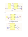
4.1 Serial Communication Connect
Module's serial port is 3.3V TTL level, so the default interface level is 3.3V. If the MCU system is 5V. It
is recommended connect a 1K resistor in series.
Figure 4.1 Serial Connect (3.3V)
DFPLayer Mini
Figure 4.2 Serial Connect (5v)
4.2. Other Refer Diagram
Figure 4.3 headset connect module
Between the headset and the module can string a 100R resistor, make a limiting
Figure 4.4 speaker connect module
DFPLayer Mini
Figure 4.5 Ad key connect refer
5、MP3-TF-16P Size (unit: mm)
Figure 5.1 pcb size
DFPLayer Mini
6、Note*
I/O Input Specification
Item
Description
Min
Type
Max
Unit
Test Condition
VIL
Low-Level Input Voltage
-0.3
-
0.3*VDD
V
VDD=3.3V
VIH
High-Level Input Voltage
0.7VDD
-
VDD+0.3
V
VDD=3.3V
I/O Output Specification
Item
Description
Min
Type
Max
Unit
Test Condition
VOL
Low-Level Output Voltage
-
-
0.33
V
VDD=3.3V
VOH
High-Level Output Voltage
2.7
-
-
V
VDD=3.3V
1. The module's external interfaces are 3.3V TTL level, so please note the level conversion during the
hardware circuit design, also in strong interference environment, electromagnetic compatibility note some
protective measures, GPIO using opt coupler isolation, increasing TVS etc.
2, ADKEY key values are in accordance with the general use of the environment, if the strong inductive or
capacitive load environment, please note that the module power supply is recommended to use a separate
isolated power supply, another matched beads and inductors for power filtering, we must ensure that the
input power as much as possible the stability and clean. If you really can not be guaranteed, please contact
us to reduce the number of keys to redefine wider voltage distribution.
3. For general Serial communication, please pay attention to level conversion. If strong interference
environment, or long distance RS485 applications, then please note that signal isolation, in strict
accordance with industry standard design communication circuits.