1
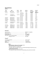
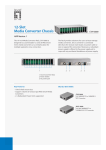
OM1001J Industrial Ethernet Media Converter One10/100/1000BASE-T port One 100/1000BASE-X SFP optical port USER MANUAL Rev. 1.2 July 7, 2014 102 WALGREEN ROAD, OTTAWA, ONTARIO, K0A 1L0 Telephone (613) 831-7777 Fax (613) 831-7778 www. luxcom.com email: [email protected] Manual Revision History Revision 1.0 Initial release April 3, 2014 Revision 1.1 extensive rewrite June 20, 2014 Revision 1.2 Correct MP05 description II Contents DESCRIPTION ................................................................................................................................................................ 1 FEATURES ..................................................................................................................................................................... 1 INDICATORS .................................................................................................................................................................. 2 SWITCHES ..................................................................................................................................................................... 3 SFP SELECTION .............................................................................................................................................................. 4 POWER INPUTS ............................................................................................................................................................. 4 ALARM RELAY ............................................................................................................................................................... 4 ORDERING INFORMATION ............................................................................................................................................ 5 WHAT IS INCLUDED....................................................................................................................................................... 5 ACCESSORIES ................................................................................................................................................................ 6 ALARM/POWER ADAPTER....................................................................................................................................................... 6 DIN RAIL MOUNTING CLIP ...................................................................................................................................................... 6 RACK MOUNT PANEL 3 UNIT .................................................................................................................................................. 6 MOUNTING BASE 1 UNIT ....................................................................................................................................................... 6 SPARE POWER CUBE .............................................................................................................................................................. 6 SPECIFICATIONS ............................................................................................................................................................ 7 WARRANTY ................................................................................................................................................................... 8 III Chapter Description The OM1001J Ethernet media converter has one 10/100/1000BASE-T electrical port and one optical SFP port. The SFP port supports a variety of wavelengths, optical speeds, and fiber types depending on which SFP module is ordered. Since both 100BASE-X and 1000BASE-X optics are supported, the optical network may be upgraded to a higher speed at a later time. The SFP type (multimode, singlemode, or bidirectional single fiber) is specified at the time of ordering, and can be seen on the label on the base of the unit (see Ordering Information). A signal strength bar graph shows the received optical power. The main connectors and switches are on the front for easy access. A DIP switch enables manual or auto configuration. There are three power inputs which accept 5 to 30 VDC from an external power cube (one supplied). Two are on the front. A third input is available on the rear connector. The rear connector also provides a power/link failure contact closure output. The rugged metal case ensures low radiated and conducted emission. Features 100BASE or 1000BASE Optics Single or multimode fiber operation Single fiber bidirectional option Received - optical power meter Distances up to 100 km Jumbo packet support SPAN or TAP mode Plug and play or manual configuration DIN rail and 19” rack mounting option Power/Link fail alarm relay Redundant power supply inputs Industrial temperature -40°C to 70°C 5 Year warranty 1 Chapter Indicators PS1 On when a 5-30V power supply is present on PS1 input. PS2 On when a 5-30V power supply is present on PS2 input or the rear panel auxiliary connector. SPEED (RJ45 Electrical Port) Green when the port is linked in 1000BASE-T Yellow when the port is linked in 100BASE-TX. Off when the port is linked in 10BASE-TX. LINK (RJ45 Electrical Port) On when a 10/100/1000BASE-T LINK is established Flashes when data is transmitted or received F-DPLX (RJ45 Electrical Port) On when the port is linked in full duplex mode Off in half-duplex mode (flashes on collision) O-LINK (Optical Port) On when OPTICAL LINK is established or forced Flashes when data is transmitted or received 1000B-X (Optical Port) On (green) when the port is in 1000BASE-X mode Off when the port is in 100BASE-X mode. Flashing indicates a non-compliant SFP module. LINK MARGIN (Bar Graph) This displays the optical link margin (remaining signal strength before link loss) in 2 dB increments. When only 1dB of link margin is left, the first indicator flashes. All indicators flash when a receiver overload condition may be present. When all the indicators are off, the optical signal is absent or weak, or an SFP without Digital Diagnostics is installed. See the SFP Selection section. For 1000BASE-X optical modules, the link margin is typically about 12 dB (six indicators on). As the fiber length increases the number of indicators decreases. The Specification section shows the link margins for different optics. 2 Chapter Switches The OM1001J has ten switches located on the front panel. These switches can be used for manual configuration if desired. The default configuration is all switches down. The switch functions are as follows: O-LPT (Optical Link Pass Through) Up disables the twisted pair transmission when to optical link is lost. This alerts the user that the optical link has failed. Down provides standard transceiver operation. E-LPT (Electrical Link Pass Through) Up disables optical port transmission when the optical or twisted pair link is lost. This alerts the user at the remote end that the local end has problems the transmitter is briefly re-enabled every five seconds to allow recovery from optical link failures. Down provides standard transceiver operation. MAN (Manual setting of electrical port) Up enables the following four switches for manual configuration; this allows connection to devices that do not support auto-negotiation. This switch does not affect O-LPT, E-LPT, or O-FL operation. Down provides standard transceiver operation (auto-negotiation and auto MDI/MDI-X) 100 Up forces 100BASE-TX electrical mode. Down enables the 10 switch. 10 Up forces 10BASE-T mode. Down forces 1000BASE-T Note that auto-negotiation is always enabled for 1000BASE-T. HDX Up forces half-duplex mode Down forces full-duplex mode This switch is ignored in 1000BASE-T mode. MDI Up leaves the electrical transmit / receive pairs as MDI. Down forces the transmit / receive pairs to swap to MDI-X. OFL* Up forces the optical link on bypassing 1000BASE-X auto-negotiation. This allows the unit to transmit packets with only the transmit fiber installed Down provides standard transceiver operation. 100-X Up places optical port in 100BASE-X optical mode Down places optical port in 1000BASE-X optical mode SPR Spare - leave down. 3 Chapter * This mode is used when the electrical port is connected to a SPAN (TAP) network port. A single fiber connection insures that no packets are injected into the port being monitored; normal Ethernet communications cannot occur in this configuration, so the optical and electrical receiving interfaces must also be configured for this mode. Optical auto-negotiation has to be disabled at the remote receiving end, or that port must allow link on a negotiation timeout; the OM1000, and OM1001J do this (so the OFL switch at the remote end need not be set). SFP Selection Several types of SFP modules are available for different Ethernet optical links. It is important that the SFP's wave length match the link partner's - 850, 1310, or 1550 nm. As well, the SFP must be compliant with the port's optical mode (100 or 1000BASE-X). The SFP modules which Luxcom supply come with digital diagnostics which enables the bar graph to display the received optical power. An SFP without digital diagnostics will allow data transmission but the power meter will not work. The 1000-LX SFPs transmit into both multimode and singlemode fiber, but the transmission distance in multimode fiber is much reduced because of bandwidth limitations caused by modal dispersion. See the Specifications section for more information. The 1000-ZX/ZXE are used for distances up to 100 km; since they use 1550 nm optics, which is not an 802.3 standard, they are usually used in matched pairs. SFP modules should only be inserted when the unit is not powered. Luxcom modules are recommended to ensure compatibility. See the Ordering Information section for the available SFP modules. Power Inputs There are three power inputs on the OM1001J – two on the front panel and one on the rear panel auxiliary input. Generally only one input is used; however more than one can be used if power supply redundancy is required. The rear panel input can be accessed using the optional ADAPTER-05. These inputs accept any voltage between 5V to 30Vdc, and the supply with the highest voltage will supply the power. The chassis of the OM1001J is connected to the negative power input; therefore any supply which is connected to it should either be floating (Class 2) or have the supplies’ negative output connected to earth (Class 1). Alarm Relay The relay contact on the modem's rear auxiliary input closes when the power supply or optical link fails. It may be used to trigger an audible of visible alarm. The Alarm is accessed using the optional ADAPTER-05 which should be specified when ordering. See the Specification section for the relay rating. 4 Chapter Ordering Information OM1001J-XX 1000-SX 1000-LX 1000-LXE 1000-ZX 1000-ZXE 1000-BU 1000-BD 100-FX 100-LX10 100-LX10E 100-BU 100-BD = 1000BASE-SX 850 nm multimode optics = 1000BASE-LX 1310 nm single/multimode optics = 1000BASE-LX 1310 nm single optics extended distance. = 1000BASE 1550 nm single-mode optics 80 km = 1000BASE 1550 nm single-mode optics 100km = 1000BASE-BX 1310 nm TX single-fiber bidirectional optics† = 1000BASE-BX 1550 nm TX single-fiber bidirectional optics† = 100BASE-FX 1310 nm multimode optics = 100BASE-LX10 1310 nm singlemode optics = 100BASE-LX10 1310 nm singlemode optics extended distance. = 100BASE-BX 1310 nm TX single-fiber bidirectional optics† = 100BASE-BX 1550 nm TX single-fiber bidirectional optics† † The single-fiber models must be used as complimentary pairs (one BU and one BD). Individual replacement optics can be ordered by specifying the XX option; for example 1000-SX. What is Included The OM1001J comes with the following: The optical module selected (with installed dust cap) A universal 5VDC AC/DC adapter User Guide 5 Chapter Accessories Alarm/Power Adapter (not included) This adapter allows the power cube to connect to the power supply input on the rear of the OM1001J. It also has screw terminals for access to the alarm relay. It should be screwed in place using the screw just above the connector. Its use is optional. Part number: ADAPTER-05 Din Rail Mounting Clip The OM1001J may be ordered with a mounting clip; this allows it to be snapped to 35mm or G-type DIN rails. Part number: DIN-CLIP-1 Rack Mount Panel 3 Unit This panel holds up to three OM1001Js, and takes 1U space in a 19” rack Part Number: MP05 Mounting Base 1 Unit This panel is screwed to a flat surface and holds one OM1001J. Thumb screws hold the modem in place. Part Number: MB05 Spare Power Cube The modem comes with a 5V, (50-60 Hz, 100 – 240Vac input) power cube with a North American power plug. If redundant power supplies are desired, an additional power cube may be connected to the second power plug on the front of the unit. It can be ordered using the following number. Part number: LTIPS-5-2.5-U. Inquire for non-North American power cubes. 6 Chapter Specifications Optical1 SFP Module 802.3 Specification Laser Source Fiber Size Optical Output 1000-SX 1000BASE-SX 850 nm 50/125 µm 62.5/125 µm 1000-LX 1000BASE-LX 1310 nm PROPRIETARY PROPRIETARY PROPRIETARY 6 6 2 3 -9 dBm -9 dBm Optical Sensitivity Minimum -18 dBm -18 dBm Optical Range Maximum 550 m 275 m 50/125 µm -9 dBm -20 dBm 1 km 1310 nm 1550 nm 1550 nm 62.5/125 µm 9/125 µm 9/125 µm 9/125 µm 9/125 µm -9 dBm -9 dBm -3 dBm 0 dBm 0 dBm -20 dBm -20 dBm -23 dBm -23 dBm -32 dBm 1 km 10 km 40 km 80 km 100 km 1000BASE-BX10 1310 nm 9/125 µm -9 dBm -20 dBm 20 km 1000-BD 1000BASE-BX10 1550 nm 9/125 µm -9 dBm -20 dBm 20 km 100-FX 100BASE-FX 1310 nm 100-LX10 4 100-LX10E 6 100-BU 6 100-BD 100BASE-LX10 PROPRIETARY 100BASE-BX10 100BASE-BX10 1310 nm 1310 nm 1310 nm 1550 nm 50/125 µm 62.5/125 µm 9/125 µm 9/125 µm 9/125 µm 9/125 µm -23 dBm -19 dBm -15 dBm -5 dBm -14 dBm -14 dBm -32.5 dBm -32.5 dBm -25 dBm -35 dBm -32.5 dBm -32.5 dBm 2 km 2 km 15 km 60 km 20 km 20 km 1000BASE-LX10 4 1000-LXE 4,5 1000-ZX 4,5 1000-ZXE 1000-BU Electrical1 Data I/O levels ............................................................................. Data I/O connector ...................................................................... Power inputs .............................................................................. Power consumption ..................................................................... Alarm relay Current continuous/peak ......................................... Voltage AC or DC..................................................... IEEE 802.3 compatible RJ45 4.8 to 30 VDC < 2.5 Watts 125/350 mA 60V peak General1 Operating temperature ................................................................ Humidity (RH) .............................................................................. MTBF ........................................................................................... Dimensions ................................................................................. -40°C to 70°C 10% to 95% > 50,000 hours 11.2 x 2.4 x 8 cm Notes: 1 Specifications are subject to change without notice. -12 Optical sensitivity measured at 10 BER. 3 The optical ranges are for typical fibers. 4 Proprietary optics have high TX power or non-standard wavelength; therefore they must interface with a similar SFP. 5 Operating temperature range is 0°C to 70°C. 6 The single-fiber models must be used as complimentary pairs (one BU and one BD). 2 7 Chapter Certification Luxcom Technologies Inc. certifies that this equipment met its published specification at the time of shipment from the factory. Warranty This Luxcom product is warranted against defects in materials and workmanship for a period of five years from the date of shipment. Luxcom will, at its option, repair or replace products that prove to be defective during the warranty period provided they are returned to Luxcom. Repairs necessitated by misuse of the product are not covered by this warranty. NO OTHER WARRANTIES ARE EXPRESSED OR IMPLIED, INCLUDING, BUT NOT LIMITED TO, THE IMPLIED WARRANTIES OF MERCHANTABILITY AND FITNESS FOR A PARTICULAR PURPOSE. LUXCOM TECHNOLOGIES INC. IS NOT LIABLE FOR CONSEQUENTIAL DAMAGES. Repackaging For Shipment Before returning the item, paperwork indicating the name, department, company and telephone number of the sender, model and serial number of the product and a brief description of the problem should be enclosed. As well, the sender must also request a Return Authorization number from Luxcom Technologies Inc. See front cover for shipping address. 8