1
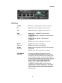
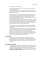
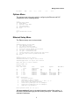
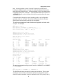
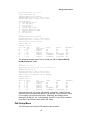
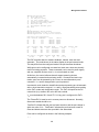
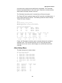
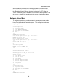
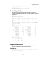
OM1006A
Industrial Ethernet Switch
Four 10/100/1000BASE-T PoE/PoE+ ports
Two 100/1000BASE-X SFP optical ports
USER MANUAL
Rev. 1.1
July 7, 2014
102 WALGREEN ROAD, OTTAWA, ONTARIO, K0A 1L0
Telephone (613) 831-7777 Fax (613) 831-7778
www. luxcom.com
email: [email protected]
This device complies with Part 15 of the FCC Rules. Operation is
subject to the following two conditions: (1) this device may not cause
harmful interference, and (2) this device must accept any interference
received, including interference that may cause undesired operation.
FCC Part 15 Class A
This Class A digital apparatus complies with Canadian ICES-003.
Cet appareil numérique de la classe A est conforme à la norme NMB-003 du Canada.
Manual Revision History
Revision 1.0 Initial release September 6, 2013
Revision 1.1 Document tap aggregator option
I
Table of Contents
Description........................................................................................................................1
USB Console Port............................................................................................................3
SFP Selection...................................................................................................................3
PoE Card...........................................................................................................................4
Power Inputs.....................................................................................................................4
Alarm Relay.......................................................................................................................5
Management Interface.....................................................................................................5
Main Menu.............................................................................................................................. 6
Options Menu........................................................................................................................ 7
Ethernet Setup Menu.............................................................................................................7
PoE Setup Menu.................................................................................................................. 11
Alarm Setup Menu............................................................................................................... 14
Software Upload Menu........................................................................................................15
Ethernet Diagnostic Menu..................................................................................................16
Register Diagnostics Menu.................................................................................................16
Reset Switch........................................................................................................................ 16
Set Password....................................................................................................................... 17
Ordering Information.....................................................................................................18
Accessories....................................................................................................................19
DIN Rail Mounting Clip........................................................................................................19
Spare Power Cube............................................................................................................... 19
Rack Mount Panel................................................................................................................ 19
Specifications.................................................................................................................20
Certification....................................................................................................................21
Warranty..........................................................................................................................21
II
Description
Description
The OM1006A Ethernet switch has four 10/100/1000BASE-T electrical ports
and two optical SFP ports. The available SFP modules support a variety of
distance requirements, wavelengths, optical speeds, and fiber types. Both
100BASE-X and 1000BASE-X SFP modules are supported for compatibility
with existing equipment. LED bar graphs show the received optical power for
each SFP making it easy to diagnose fiber connection problems.
Power over Ethernet (PoE) support is optional. The four RJ45 Ethernet ports
can support either PoE or PoE+ as per IEEE Std 802.3at-2009. This allows
convenient connection of surveillance cameras, wireless access points and IP
phones in situations where local power is not readily available. The OM1006A
can deliver up to 30 Watts of power per port. Total power delivery depends on
the supplied power adapter(s). Both Alternative A and Alternative B pinouts
are supported.
All connectors are on the front for easy access. The OM1006A has redundant
power inputs. Power adapters are available for both non PoE and PoE
applications. A relay contact closure is provided for alarms on link, power and
PoE power delivery. A USB serial console interface is provided for status,
configuration and software updates.
The OM1006A is designed to meet the requirements of IEEE 802.3at-2009
(Environment A) and the electrical safety requirements of UL60950-1.
The compact rugged metal enclosure ensures low radiated and conducted
emissions. It can be DIN rail or 19” rack mounted with optional hardware.
The OM1006A can operate in several modes. It can be configured as a
standard six port switch. Ports 5 and 6 can be configured as a redundant fiber
trunk. It can function as a dual media-converter or port-to-port dual mediaconverter. Finally, it can be configured in a secure 802.1Q VLAN port fan out
mode for segregated traffic.
Features
Two 100BASE-X/1000BASE-X
optical SFP ports
Single or multimode fiber
operation
Single fiber bidirectional option
Receive optical power meters
Distances up to 100 km
Power over Ethernet
1
Four 10/100/1000BASE-T ports
DIN rail and 19” rack mounting
option
Power/PoE/Link fail alarm relay
Redundant power supply inputs
Industrial temperature -40°C to
70°C
5 Year warranty
Description
Indicators
ALARM
Red when an enabled alarm condition is present.
PS1
Green when power is applied to power input 1.
PS2
Green when power is applied to power input 2.
LINK
(Ports 1-4)
Green when a 1000BASE-T LINK has been
established.
Orange-Green when a 100BASE-TX LINK has been
established.
Orange when a 10BASE-T LINK has been
established.
Flashes when data is transmitted or received.
HDPLX
(Ports 1-4)
Yellow when the port is half duplex.
Off when the port is not in half duplex.
O-LINK
(Ports 5-6)
Green when a bidirectional OPTICAL LINK has been
established.
Flashes when data is transmitted or received.
LINK MARGIN
(Ports 5-6)
This bar graph displays the optical link margin
(remaining signal strength before link loss) in 2 dB
increments. When less than1dB of link margin is left,
the first indicator flashes. All indicators flash when a
receiver overload condition may be present. When all
the indicators are off, the optical signal is absent or
weak, or an SFP without Digital Diagnostics is
installed. See the SFP Selection section. For
1000BASE-X optical modules, the link margin is
typically about 12 dB (six indicators on). As the fiber
length increases the number of indicators decreases.
The Specification section shows the link margins for
different optics.
2
USB Console Port
The OM1006A has an isolated USB mini B console interface using a USB
UART. The UART is USB bus powered, so the OM1006A's status can be
observed at power on. The port settings are 38400 bps, 8 data bits, no parity, 1
stop bit and no flow control.
Windows systems require installation of a FTDI Chip device driver. The system
will prompt to install the driver when the OM1006A is first connected. The
driver can be downloaded automatically from the Internet or manually from
FTDI.
Windows allocates a USB serial COM port when the OM1006A is connected
but it doesn't inform the user as to which port it allocated. This can be
determined by opening the Ports (COM & LPT) tab in the Windows Device
Manager.
The OM1006A is shipped with a fixed USB device serial number (12345678).
As a result, the same driver instance is selected by Windows for all units. If
multiple OM1006A units are connected to a USB hub, it may be desirable to
program different serial numbers for each unit. This can be done with the FTDI
MProg application.
A serial terminal program such as HyperTerminal, Tera Term Pro or Putty is
required to connect to the OM1006A console interface. For software uploads,
the program must support the Xmodem protocol. Connect to the OM1006A
using the selected COM port and terminal settings shown above.
See the Management Interface section for information on configuring the
OM1006A.
SFP Selection
Several types of SFP modules are available for different Ethernet optical links.
It is important that the SFP's wave length match the link partner's - 850, 1310,
or 1550 nm. As well, the SFP must be compliant with the port's optical mode
(100BASE-X or 1000BASE-X).
The SFP modules supplied by Luxcom have digital diagnostics which enable
the bar graphs to display received optical power. Detailed diagnostic
information is also available using the console interface. SFPs without digital
diagnostics can be used but the power meters will not work.
The Luxcom 1000-LX SFP transmits into both multimode and singlemode fiber,
but the transmission distance in multimode fiber is greatly reduced because of
bandwidth limitations caused by modal dispersion. Modal dispersion varies
greatly from fiber to fiber. The 1000-LX distances in multimode fiber assume
that a mode conditioning patch cord is installed. See the Specifications
section for more information.
The 1000-ZX/ZXE SFP is used for distances up to 100 km. It uses 1550 nm
laser optics. These optics are usually used in matched pairs because the
3
SFP Selection
optical transmit and receive specifications are not standardized.
SFP modules should only be inserted when the unit is not powered. This
avoids I2C bus faults that sometimes occur when a module is inserted.
Luxcom modules are recommended to ensure compatibility.
See the Ordering Information section for the available SFP modules.
PoE Card
When the OM1006A is shipped with a PoE card, it is shipped with the PoE
jumpers positioned for “Alternative A” (jumpers toward middle of card). The
jumpers can be repositioned for “Alternative B” (power on spare pairs) by
moving the jumpers to the edge of the card. There are two jumpers per port
and they both have to be positioned identically.
The eight internal PoE jumpers can be removed for non PoE applications.
This ensures power supply isolation from the MDI pins.
Power Inputs
Currently, Luxcom provides a 60 Watt 56V supply for PoE+ and a 70 Watt
48V supply for PoE. A 12V supply is provided for non PoE applications.
These supplies have a maximum operating temperature of 40°C except for the
70 Watt supply. It can operate at ambient temperatures up to 60°C but it's
output must be derated to 56 Watts at this temperature.
There are two power inputs on the OM1006A. Generally only one input is
used; however both may be used for redundancy. The higher voltage supply
powers the unit. Power sharing can occur when both inputs are at the same
voltage.
When the PoE card is not installed, both power inputs can be any voltage
between 9.0V and 36.0V.
The following considerations must be taken into account when using non
Luxcom power supplies.
The unit accepts 2.1 x 5.5 x 9.5 mm center positive barrel connectors.
For PoE operation, a 48V, 54V or 56V supply must be used. The minimum
input voltage is 45.0 V and the maximum 57.0 V. For PoE+ operation, a 54V
or 56V supply must be used and the minimum voltage is 51.0 V. The control
logic turns on at approximately 31.6 V. It turns off at 29.5 V. On over-voltage,
it turns off at approximately 62.7 V and on at 60.3 V.
In order to meet safety regulations and the requirements of IEEE 802.3at, the
OM1006A must be powered by one or two fully isolated power supplies
(IEC/EN 61140 protection class II, double insulated). Frame ground must not
be connected to any power lead. The supply must be capable of withstanding
2250 VDC between its outputs and frame ground if present. The power
4
Power Inputs
conductors must not be accessible.
Class II supplies typically have a C8 or C18 A/C connector, and the double
insulated icon on the label.
Power adapters with a C14 A/C connector are typically Class 1 supplies and
frame ground is connected to the secondary V- output. Thus, they don't meet
the isolation requirement.
A protection class II supply is not the same as a Class 2 supply. A Class 2
Power Supply does not have to be double insulated. Class 2 supplies are
limited to a maximum output of less than 100 Watts. They have reduced
requirements regarding insulation, wire size, derating factors, and over-current
protection compared to Class 1 supplies.
The OM1006A is a limited power source as defined in IEC 60950-1. Each PoE
output is independently fused. This limits the maximum output current per port
to less than 1.75 A and the maximum output power to less than100 Watts. In
normal operation, this limit should never occur as the PoE port controller limits
output current based on port classification and PoE mode.
The maximum power output of the OM1006A is limited by supply capability.
Care must be taken to ensure that the output load doesn't drag down the input
supply voltage.
The input voltage to the PoE controller (Vee) is monitored to ensure that the
port output voltages comply with the requirements of IEEE Std 802.3at-2009.
The minimum port voltage is 44.0 V and 50.0 V for PoE and PoE+,
respectively. The ports are shutdown on over-voltage and under-voltage
conditions. Brief under-voltage transients are permitted as long as they aren't
more than 7.6 % below the minimum port voltage. Low priority ports are
shutdown first when a small under-voltage is present.
Alarm Relay
The relay contact on the front of the modem closes when a monitored
condition fails or the control microprocessor fails to open the relay contact.
Alarm conditions are set using the console. The contact closure may be used
to trigger an audible or visible alarm. See the Specification section for the
relay rating.
Management Interface
The OM1006A has a menu driven management interface to display status of
subsystems and to configure the unit. The menu system is hierarchical. Menu
actions are specified by entering a single alphanumeric character. A <CR>
causes the current menu to redisplay. <ESC> goes up one menu level except
at the top level. <ESC> can also be used to abort numeric and string entries.
This causes the action to be aborted.
5
Management Interface
Main Menu
The main menu is shown below and some of its status displays:
OM1006 Main Menu
1)
Show Ethernet status
2)
Show PoE status
3)
Show SFP status
4)
Options menu
5)
Software upload menu
6)
Ethernet diagnostics menu
7)
Register diagnostics menu
8)
Reset switch
9)
Set password
:> 1
OM1006A Ethernet Switch (merlin)
OM1006A BootLoader 1.0 May 07 2012 11:50:01
OM1006A Application 1.0 Sep 14 2012 09:26:30
Mode: SFP ports (5 and 6) trunked
Monitor Mode: Off
Ethernet Status
Port VID Link
Auto
Speed
Good
Negotiation
P1
0 No
Enabled
NA
P2
0 No
Enabled
NA
P3
0 No
Enabled
NA
P4
0 Yes
Enabled
100BASE-TX
P5
0 Yes
Enabled
1000BASE-X
P6
0 Yes
Enabled
1000BASE-X
:> 2
OM1006A Ethernet Switch (merlin)
OM1006A BootLoader 1.0 May 07 2012 11:50:01
OM1006A Application 1.0 Sep 14 2012 09:26:30
PoE Status and Configuration
Port PwrGood PwrEnable
Class
P1
No
Off
Unknown
P2
No
Off
Unknown
P3
No
Off
Unknown
P4
No
Off
Unknown
Port
P1
P2
P3
P4
Priority
High
High
High
High
PoE+
Yes
Yes
Yes
Yes
DisconEn
Yes
Yes
Yes
Yes
Duplex
MDI/MDI-X
NA
NA
NA
Full-Duplex
Full-Duplex
Full-Duplex
NA
NA
NA
MDI-X
NA
NA
Detect
Ropen
Ropen
Ropen
Ropen
Mode
Icut (mA)
Automatic
374.4
Automatic
374.4
Automatic
374.4
Automatic
374.4
Current (mA)
0.0
0.0
0.0
0.0
Vee (Volts) OverTemp VeeUVLO AltB HRev
FRev
-53.069
No
No
No
b
0.2.79
:> 3
OM1006A Ethernet Switch (merlin)
OM1006A BootLoader 1.0 May 07 2012 11:50:01
OM1006A Application 1.0 Sep 14 2012 09:26:30
Port 5: SFP Diagnostic Values
Parameter Units
Value
High
Alarm
T
C
46.6
100.0
Vcc
V
3.18
5.00
TX Bias
mA
30.7
100.0
TX Power
dBm
-4.6
7.0
RX Power
dBm
-4.5
7.0
Low
Alarm
-50.0
0.00
0.0
-40.0
-40.0
High
Warning
100.0
5.00
100.0
7.0
7.0
Low
Warning
-50.0
0.00
0.0
-40.0
-40.0
Port 6: SFP Diagnostic Values
Parameter Units
Value
High
Alarm
T
C
43.2
90.0
Vcc
V
3.32
3.50
TX Bias
mA
16.8
100.1
TX Power
dBm
-5.8
-3.0
Low
Alarm
-45.0
3.10
6.0
-9.5
High
Warning
85.0
3.45
90.0
-3.5
Low
Warning
-40.0
3.15
7.0
-9.0
6
Management Interface
RX Power
dBm
-4.9
-3.0
-21.0
-3.5
-20.5
Options Menu
The options menu is the entry point for configuring the Ethernet and PoE
subsystems, and for enabling alarms:
:> 4
OM1006A Options Menu
1)
Name modem
2)
Ethernet setup menu
3)
PoE setup menu
4)
Alarm setup menu
Esc Back
:> 1
Enter modem name: merlin
:>
Ethernet Setup Menu
The Ethernet setup menu is shown below:
:> 2
OM1006A Ethernet Options Menu
1)
Show Ethernet status
2)
Set switch operation mode
3)
Enable port auto negotiation
4)
Force port speed, duplex and crossover
5)
Set port 5 transceiver mode
6)
Set port 6 transceiver mode
7)
Setup monitoring (mode, destination and source)
8)
Set port VID for 802.1Q VLAN switch mode
Esc Back
:> 1
OM1006A Ethernet Switch (merlin)
OM1006A BootLoader 1.0 May 07 2012 11:50:01
OM1006A Application 1.0 Sep 14 2012 09:26:30
Mode: SFP ports (5 and 6) trunked
Monitor Mode: Off
Ethernet Status
Port VID Link
Auto
Speed
Duplex
Good
Negotiation
P1
0 No
Enabled
NA
NA
P2
0 No
Enabled
NA
NA
P3
0 No
Enabled
NA
NA
P4
0 Yes
Enabled
100BASE-TX
Full-Duplex
P5
0 Yes
Enabled
1000BASE-X
Full-Duplex
P6
0 Yes
Enabled
1000BASE-X
Full-Duplex
:> 2
Mode
Description
0
All ports switched
1
SFP ports (5 and 6) trunked
2
Dual media-converter (ports 1, 2, 5 and 3, 4, 6)
3
Port-to-port dual media-converter
4
Secure 802.1Q VLAN port fan out (EndSpan)
5
Secure 802.1Q VLAN port fan out (MidSpan)
6
SPAN port tap aggregator
MDI/MDI-X
NA
NA
NA
MDI-X
NA
NA
Enter operation mode (0 to 6) [0]: 1
“All ports switched” mode is the default operation mode of the modem. In
this mode, packets entering a port can exit any other port. The switch learns
destination addresses.
7
Management Interface
“SFP ports (5 and 6) trunked” mode is similar except ports 5 and 6 are
trunked for added performance and link reliability. Two units must be used
back-to-back in this mode. A hash algorithm based on the source and
destination addresses of a packet is used for load balancing. If link fails on
one port, its traffic is switched over to the remaining port.
“Dual media-converter” mode splits the unit into two separate three port
switches using port-based VLANs. The two port groups are completely
separate and packets cannot cross the VLAN boundary. Within a port group,
packets are switched in the default manner. Ports 1, 2 and 5 make up one
group and ports 3, 4 and 6 the other group.
“Port-to-port dual media-converter” mode is a special mode to carry up to
four separated streams between a pair of media converters connected back-toback. Port 1 on converter 1 connects to port 1 on converter 2, etc. Packets
are restricted by port-based VLANs and interchip tagging from exiting any
other port.
“Secure 802.1Q VLAN port fan out (EndSpan)” mode is similar to the “Portto-port dual media-converter” mode in that 802.1Q VLAN tags are used to
restrict ports 1 through 5 to a single VLAN. So, if a pair of media converters
are connected back-to-back using port 6 and both port 1's are set to VLAN ID
1, then port 1 on converter 1 will only connect to port 1 on converter 2.
Packets are restricted by port-based VLANs and 802.1Q tags from exiting any
other port.
Because this mode uses 802.1Q tags, the mode is not transparent to tagged
packets. When a packet enters port 1, it exits port 6 with a VLAN tag
containing port 1's VLAN ID (VID). If a VLAN tagged packet enters port 1, its
VID is replaced by port 1's VID. When a packet exits port 1, its VLAN tag is
removed. Packets exiting port 6 are always tagged. All untagged packets
entering port 6 are dropped. A tagged packet entering port 6 will be dropped if
it is not a member of the VLAN VTU database or if the egress port specified in
the VTU database is not allowed by the port-based VLAN settings. Further,
each VLAN uses a separate forwarding information database to ensure that
packets can't tunnel between VLANs. Monitoring is also disabled in this mode.
For these reasons, the mode is termed secure.
Port 6 can be connected to a larger managed switch that can switch VLANs.
In this way, up to five separate VLANs can be securely distributed to a location
using fiber. As the tagging is all done by the OM1006A, the attached
equipment doesn't have to be VLAN aware. The managed switch can perform
device authentication (802.1X) if desired.
Port 6 can also connect to a OM1006A in “Secure 802.1Q VLAN port fan out
(MidSpan)” mode. This mode is similar to the “Secure 802.1Q VLAN port fan
out (EndSpan)” mode except that both ports 5 and 6 are tagged VLAN ports.
This allows a string of OM1006A modems to interconnect a set of VLANs. The
VID assigned to a port must be unique within a modem and each modem can
switch a maximum of 64 VLANs.
“SPAN port tap aggregator” is a special mode to aggregate Ethernet wire
8
Management Interface
taps. Incoming packets on ports 1 through 5 egress only on fiber port 6.
Learning is disabled on ports 1 through 5 to ensure that packets received on
these ports are flooded to port 6. Incoming packets on port 6 are dropped and
no packets egress ports 1 through 5. Auto-negotiation still occurs on port 6 in
1000BASE-X mode, so the link status for this port correctly reflects the status
of the fiber link.
Commands which change the current operating mode or port configuration
generally result in a unit reset. The causes the Ethernet switch to be reset,
shutting down all ports briefly until they are reconfigured.
The next two commands are used to enable auto-negotiation or forced mode
on a port. For example,
:> 4
Enter
Enter
Enter
Enter
port (1 to 4): 3
speed (0 = 100BASE-TX, 1 = 10BASE-T) [0]:
duplex mode (0 = full duplex, 1 = half duplex) [0]:
crossover mode (0 = MDI-X, 1 = MDI) [0]:
:> 1
OM1006A Ethernet Switch (merlin)
OM1006A BootLoader 1.0 May 07 2012 11:50:01
OM1006A Application 1.0 Sep 14 2012 09:26:30
Mode: SFP ports (5 and 6) trunked
Monitor Mode: Off
Ethernet Status
Port VID Link
Auto
Speed
Good
Negotiation
P1
0 No
Enabled
NA
P2
0 No
Enabled
NA
P3
0 No
Disabled
100BASE-TX
P4
0 Yes
Enabled
100BASE-TX
P5
0 Yes
Enabled
1000BASE-X
P6
0 Yes
Enabled
1000BASE-X
:> 3
Enter port (1 to 4): 3
:> 1
OM1006A Ethernet Switch (merlin)
OM1006A BootLoader 1.0 May 07 2012 11:50:01
OM1006A Application 1.0 Sep 14 2012 09:26:30
Duplex
MDI/MDI-X
NA
NA
Full-Duplex
Full-Duplex
Full-Duplex
Full-Duplex
NA
NA
MDI-X
MDI-X
NA
NA
Speed
Duplex
MDI/MDI-X
NA
NA
NA
100BASE-TX
1000BASE-X
1000BASE-X
NA
NA
NA
Full-Duplex
Full-Duplex
Full-Duplex
NA
NA
NA
MDI-X
NA
NA
Mode: SFP ports (5 and 6) trunked
Monitor Mode: Off
Ethernet Status
Port VID Link
Good
P1
0 No
P2
0 No
P3
0 No
P4
0 Yes
P5
0 Yes
P6
0 Yes
Auto
Negotiation
Enabled
Enabled
Enabled
Enabled
Enabled
Enabled
The next two commands configure ports 5 and 6 to 1000BASE-X or 100BASEFX. For example,
:> 5
Enter port mode (0 = 1000BASE-X, 1 = 100BASE-FX): 0
The final Ethernet setup command is to setup port monitoring. This involves
selecting a monitor mode, and destination and source ports. Ports 5 and 6
cannot be used as a monitor source or destination in the “SFP ports (5 and 6)
9
Management Interface
trunked” and “Port-to-port dual media-converter” modes.
Here is an example showing the mirroring setup:
:> 7
Mode
0
1
2
3
Description
Monitoring off
Ingress monitoring
Egress monitoring
Ingress and Egress monitoring
Enter monitor mode (0 to 3) [0]: 1
Enter monitor destination port (1 to 4): 1
Enter monitor source port (1 to 4): 4
Luxcom Technologies Inc.
OM1006A Ethernet Switch (merlin)
OM1006A BootLoader 1.0 May 07 2012 11:50:01
OM1006A Application 1.0 Sep 14 2012 09:26:30
OM1006 Main Menu
1)
Show Ethernet status
2)
Show PoE status
3)
Show SFP status
4)
Options menu
5)
Software upload menu
6)
Ethernet diagnostics menu
7)
Register diagnostics menu
8)
Reset switch
9)
Set password
:> 1
OM1006A Ethernet Switch (merlin)
OM1006A BootLoader 1.0 May 07 2012 11:50:01
OM1006A Application 1.0 Sep 14 2012 09:26:30
Mode: SFP ports (5 and 6) trunked
Monitor Mode: Ingress, Destination port 1, Source port 4
Ethernet Status
Port VID Link
Good
P1
0 No
P2
0 No
P3
0 No
P4
0 Yes
P5
0 Yes
P6
0 Yes
:> 4
OM1006A Options Menu
1)
Name modem
2)
Ethernet setup menu
3)
PoE setup menu
4)
Alarm setup menu
Esc Back
Auto
Negotiation
Enabled
Enabled
Enabled
Enabled
Enabled
Enabled
Speed
Duplex
MDI/MDI-X
NA
NA
NA
100BASE-TX
1000BASE-X
1000BASE-X
NA
NA
NA
Full-Duplex
Full-Duplex
Full-Duplex
NA
NA
NA
MDI-X
NA
NA
:> 2
OM1006A Ethernet Options Menu
1)
Show Ethernet status
2)
Set switch operation mode
3)
Enable port auto negotiation
4)
Force port speed, duplex and crossover
5)
Set port 5 mode
6)
Set port 6 mode
7)
Setup monitoring (mode, destination and source)
Esc Back
:> 7
Mode
0
1
2
3
Description
Monitoring off
Ingress monitoring
Egress monitoring
Ingress and Egress monitoring
10
Management Interface
Enter monitor mode (0 to 3) [0]:
Luxcom Technologies Inc.
OM1006A Ethernet Switch (merlin)
OM1006A BootLoader 1.0 May 07 2012 11:50:01
OM1006A Application 1.0 Sep 14 2012 09:26:30
OM1006 Main Menu
1)
Show Ethernet status
2)
Show PoE status
3)
Show SFP status
4)
Options menu
5)
Software upload menu
6)
Ethernet diagnostics menu
7)
Register diagnostics menu
8)
Reset switch
9)
Set password
:> 1
OM1006A Ethernet Switch (merlin)
OM1006A BootLoader 1.0 May 07 2012 11:50:01
OM1006A Application 1.0 Sep 14 2012 09:26:30
Mode: SFP ports (5 and 6) trunked
Monitor Mode: Off
Ethernet Status
Port VID Link
Good
P1
0 No
P2
0 No
P3
0 No
P4
0 Yes
P5
0 Yes
P6
0 Yes
Auto
Negotiation
Enabled
Enabled
Enabled
Enabled
Enabled
Enabled
Speed
Duplex
MDI/MDI-X
NA
NA
NA
100BASE-TX
1000BASE-X
1000BASE-X
NA
NA
NA
Full-Duplex
Full-Duplex
Full-Duplex
NA
NA
NA
MDI-X
NA
NA
The following example shows how to set the port VID for “Secure 802.1Q
VLAN port fan out” mode:
:> 8
Enter port (1 to 5): 1
Enter unique port VID (1-4094 or 0 to isolate)[1]: 1
:> 1
OM1006A Ethernet Switch
OM1006A BootLoader 1.0 Apr 12 2013 11:48:17
OM1006A Application 1.4 Aug 13 2013 17:03:03
Mode: Secure 802.1Q VLAN port fan out (EndSpan)
Monitor Mode: Off
Ethernet Status
Port VID Link
Good
P1
1 No
P2
2 No
P3
0 No
P4
0 No
P5
0 No
P6
0 Yes
Auto
Negotiation
Enabled
Enabled
Enabled
Enabled
Enabled
Enabled
Speed
Duplex
MDI/MDI-X
NA
NA
NA
NA
1000BASE-X
1000BASE-X
NA
NA
NA
NA
NA
Full-Duplex
NA
NA
NA
NA
NA
NA
A port can be set to any unique VID between 1 and 4094. VLAN IDs 0 and
4095 are reserved for special purposes in VLAN tags. We use an entry value
of 0 to isolate a port from all other ports. Effectively, this disables a port
although it will still link. So, in the example, ports P3, P4 and P5 are isolated
and ports P1 and P2 have their default VID values.
PoE Setup Menu
The PoE setup menu and the PoE status are shown below:
11
Management Interface
OM1006A PoE Options Menu
1)
Show PoE status
2)
Set PoE port config
3)
Set port current limit
4)
Power on manual/semiauto ports
5)
Shutdown low-priority ports
6)
Reset PoE chip
7)
Reconfigure shutdown ports
Esc Back
:> 1
OM1006A Ethernet Switch (merlin)
OM1006A BootLoader 1.0 May 07 2012 11:50:01
OM1006A Application 1.0 Sep 14 2012 09:26:30
PoE Status and Configuration
Port PwrGood PwrEnable
Class
P1
No
Off
Unknown
P2
No
Off
Unknown
P3
No
Off
Unknown
P4
No
Off
Unknown
Port
P1
P2
P3
P4
Priority
High
High
High
High
Vee (Volts)
-53.248
PoE+
Yes
Yes
Yes
Yes
OverTemp
No
DisconEn
Yes
Yes
Yes
Yes
VeeUVLO
No
Detect
Ropen
Ropen
Ropen
Ropen
Mode
Icut (mA)
Automatic
374.4
Automatic
374.4
Automatic
374.4
Automatic
374.4
AltB
No
HRev
b
Current (mA)
0.0
0.0
0.0
0.0
FRev
0.2.79
The PoE controller has four modes: shutdown, manual, semi-auto and
automatic. The mode shown in the status display is the port's actual mode.
This may differ from the configured mode if the port has been shutdown.
While ports can be configured to manual and semi-auto, these are primarily
useful for testing purposes. These commands can be used to power legacy
and non compliant devices since ICUT is not set based on class.
At this time, the control software doesn't support powering devices
automatically in manual and semi-auto modes. In manual and semi-auto
modes, ports can be powered by the “Power on manual/semiauto ports”
command. ICUT can be changed after a port is powered.
In automatic mode, detection classification and port powering are all automatic
with no host intervention required. ICUT and ILIM are automatically set according
to the PoE+ mode and classification result. The PoE+ bit specifies the DC
current limit (ILIM) at either 425 mA or 850 mA nominal.
VEE must be between 50.0 V and 57.0 V if any port is configured for PoE+.
The “DisconEn” bit must be set to remove power on disconnect. Normally,
disconnect enable should be on.
“PwrGood” indicates that the port has been turned on and the port voltage is
within two volts of VEE. “PwrEnable” indicates the port has been turned on.
Class and detect status are also provided in the status data.
Ports can be configured as shown in the following example:
:> 2
12
Management Interface
Enter port (1 to 4): 1
PoE Port Configuration
Bits Description
4 0 = High priority
1 = Low priority
3 0 = PoE
1 = PoE+
2 0 = DisconEn Off
1 = DisconEn On
1:0 0 = Shutdown
1 = Manual
2 = Semiauto
3 = Auto
Enter port config (hex) [0x0F]: 1f
:> 1
OM1006A Ethernet Switch (merlin)
OM1006A BootLoader 1.0 May 07 2012 11:50:01
OM1006A Application 1.0 Sep 14 2012 09:26:30
PoE Status and Configuration
Port PwrGood PwrEnable
Class
P1
No
Off
Unknown
P2
No
Off
Unknown
P3
No
Off
Unknown
P4
No
Off
Unknown
Port
P1
P2
P3
P4
Priority
Low
High
High
High
PoE+
Yes
Yes
Yes
Yes
DisconEn
Yes
Yes
Yes
Yes
Detect
Unknown
Ropen
Ropen
Ropen
Mode
Icut (mA)
Shutdown
374.4
Automatic
374.4
Automatic
374.4
Automatic
374.4
Current (mA)
0.0
0.0
0.0
0.0
Vee (Volts) OverTemp VeeUVLO AltB HRev
FRev
-53.248
No
No
No
b
0.2.79
:> 3
Enter port (1 to 4): 1
Enter port Icut (3.2 mA * hex) [0x75]: 0x80
:> 1
OM1006A Ethernet Switch (merlin)
OM1006A BootLoader 1.0 May 07 2012 11:50:01
OM1006A Application 1.0 Sep 14 2012 09:26:30
PoE Status and Configuration
Port PwrGood PwrEnable
Class
P1
No
Off
Unknown
P2
No
Off
Unknown
P3
No
Off
Unknown
P4
No
Off
Unknown
Port
P1
P2
P3
P4
Priority
Low
High
High
High
Vee (Volts)
-53.248
PoE+
Yes
Yes
Yes
Yes
OverTemp
No
DisconEn
Yes
Yes
Yes
Yes
VeeUVLO
No
Detect
Unknown
Ropen
Ropen
Ropen
Mode
Icut (mA)
Shutdown
409.6
Automatic
374.4
Automatic
374.4
Automatic
374.4
AltB
No
HRev
b
Current (mA)
0.0
0.0
0.0
0.0
FRev
0.2.79
It is not valid to change the PoE+ bit after a port has been powered. Thus,
ports are reset (shutdown) prior to reconfiguration. The configuration and I CUT
value for a port are restored by doing a microcontroller reset or power on.
The “Power on manual/semiauto ports” command attempts to turn-on ports in
manual or semi-auto mode. It doesn't turn-on shutdown or automatic ports.
In the semi-auto mode, port turn-on is delayed until the next detection and
classification. The port will not power if the detection or classification is not
valid.
13
Management Interface
In manual mode, detection and classification are disabled. The commands
forces a single classification to turn-on the port. Detection is not done and the
detect status will always indicate “Unknown”.
The “Shutdown low-priority ports” command turns off low priority ports.
The “Reset PoE chip” command resets the PoE controller to its default state. It
can be useful testing PoE devices. The following shows the result of doing a
“Reset PoE chip” command:
:> 6
:> 1
OM1006A Ethernet Switch (merlin)
OM1006A BootLoader 1.0 May 07 2012 11:50:01
OM1006A Application 1.0 Sep 14 2012 09:26:30
PoE Status and Configuration
Port PwrGood PwrEnable
Class
P1
No
Off
Unknown
P2
No
Off
Unknown
P3
No
Off
Unknown
P4
No
Off
Unknown
Port
P1
P2
P3
P4
Priority
High
High
High
High
Vee (Volts)
-53.248
PoE+
No
No
No
No
OverTemp
No
DisconEn
Yes
Yes
Yes
Yes
Detect
Unknown
Unknown
Unknown
Unknown
Mode
Shutdown
Shutdown
Shutdown
Shutdown
VeeUVLO
No
AltB
No
HRev
b
Icut (mA)
374.4
374.4
374.4
374.4
Current (mA)
0.0
0.0
0.0
0.0
FRev
0.2.79
Finally, the “Reconfigure shutdown ports” command attempts to reconfigure
shutdown ports. The command may fail if one or more ports have been
shutdown due to over-current, under-voltage, etc, and the fault hasn't been
corrected.
Alarm Setup Menu
The alarm setup menu is shown below:
OM1006 Alarm Options Menu
0)
Show alarm status
1)
Toggle port 1 link alarm enable
2)
Toggle port 2 link alarm enable
3)
Toggle port 3 link alarm enable
4)
Toggle port 4 link alarm enable
5)
Toggle port 5 link alarm enable
6)
Toggle port 6 link alarm enable
7)
Toggle power 1 input alarm enable
8)
Toggle power 2 input alarm enable
Esc Back
:> 1
Alarm
Port 1
Port 2
Port 3
Port 4
Port 5
Port 6
Power 1
Power 2
:>
Description
Link Lost
Link Lost
Link Lost
Link Lost
Link Lost
Link Lost
Input Lost
Input Lost
Alarmed
Yes
No
No
No
No
No
No
No
Status
LOST
14
Management Interface
Alarm enables are provided for the following conditions: link lost for ports 1
through 6, and power supply inputs 1 and 2. When an alarm is enabled and
the alarmed condition is present, the status is shown as “LOST”. When a
“LOST” condition is present, the alarm LED is turned on and the contact on the
alarm relay is closed. One can determine the source using the “Show alarm
status” command.
Software Upload Menu
The software upload menu provides a means to upload new software and to
view the status of current uploads. It uses the xmodem protocol available in
HyperTerminal® and other terminal programs. The example below shows a
sample upload:
:> 5
Software Upload Menu
1)
Show stored files
2)
Upload new BACKUP
3)
Swap BACKUP and PRIMARY
4)
Reprogram card with PRIMARY
Esc Back
:> 1
PRIMARY MCU software file
Model: OM1006A Ethernet Switch
Card: OM1006A Application 1.0 Sep 14 2012 09:26:30
BACKUP MCU software file
Model: OM1006A Ethernet Switch
Card: OM1006A Application 1.0 Sep 14 2012 09:26:30
:> 2
Delete BACKUP file (y/n): y
Start Xmodem transfer (Send File)
CCC
File upload successful
65536 bytes uploaded
:> 3
BACKUP file is now PRIMARY file
:> 4
Flash command issued successfully.
Luxcom Technologies Inc.
OM1006A Ethernet Switch (merlin)
OM1006A BootLoader 1.0 May 07 2012 11:50:01
OM1006A Application 1.0 Sep 14 2012 13:55:29
OM1006 Main Menu
1)
Show Ethernet status
2)
Show PoE status
3)
Show SFP status
4)
Options menu
5)
Software upload menu
6)
Ethernet diagnostics menu
7)
Register diagnostics menu
8)
Reset switch
9)
Set password
:> 5
Software Upload Menu
1)
Show stored files
2)
Upload new BACKUP
3)
Swap BACKUP and PRIMARY
4)
Reprogram card with PRIMARY
Esc Back
:> 1
PRIMARY MCU software file
Model: OM1006A Ethernet Switch
15
Management Interface
Card: OM1006A Application 1.0 Sep 14 2012 13:55:29
BACKUP MCU software file
Model: OM1006A Ethernet Switch
Card: OM1006A Application 1.0 Sep 14 2012 09:26:30
Ethernet Diagnostic Menu
This menu provides information about the register state of the Ethernet
controller, port MIB statics, and cable tests. The menu and sample outputs are
shown below:
:> 6
OM1006 Ethernet Diagnostic
1) Show port 1 registers
test
2) Show port 2 registers
test
3) Show port 3 registers
test
4) Show port 4 registers
test
5) Show port 5 registers
6) Show port 6 registers
7) Show global registers
Esc Back
Menu
a) Show port 1 statistics
g) Do port 1 cable
b) Show port 2 statistics
h) Do port 2 cable
c) Show port 3 statistics
i) Do port 3 cable
d) Show port 4 statistics
j) Do port 4 cable
e) Show port 5 statistics
f) Show port 6 statistics
k) Dump ATU database
l) Dump VTU database
:> d
Packet Statistics for Port 4
InGoodOctestsLo:
9807,
InBadOctets:
0,
InUnicast:
40,
InBroadcasts:
12,
64Octets:
478,
128 to 256Octets:
201,
512 to 1023Octets:
74,
OutOctetsLo:
292384,
OutUnicast:
568,
OutMultcasts:
466,
Single:
0,
InPause:
0,
InUndersize:
0,
InOversize:
0,
InRXErr:
0,
Collisions:
0,
:> j
Port 4 Virtual Cable Test
Pair Polarity Amplitude Distance
0
1
0x00
0x00
1
1
0x00
0x00
2
0
0x55
0x09
3
0
0x58
0x09
InGoodOctestsHI:
OutFCSErr:
Deferred:
InMulticasts:
65 to 127Octets:
256 to 511Octets:
1024 to MaxOctets:
OutOctetsHi:
Excessive:
OutBroadcasts:
OutPause:
Multiple:
InFragments:
InJabber:
InFCSerr:
Late:
0
0
0
20
714
275
13
0
0
649
0
0
0
0
0
0
Register Diagnostics Menu
The register diagnostics menu provides raw register dumps from various
devices in the OM1006A for factory diagnostic purposes.
Reset Switch
This command resets the control microprocessor and Ethernet switch. This
restores the saved configuration.
16
Management Interface
Set Password
This command changes the unit's password. It is used to control access to
configurable data in the “Options menu”. Password processing can be
disabled by entering an empty password. The password prompt has a 120
second keyboard timeout delay. Here is an example:
:> 9
Enter old password: ******
Enter new password: *****
Reenter new password: *****
Password successfully changed
The default password as shipped is “luxcom”.
17
Ordering Information
Ordering Information
OM1006A-T5-T6-P-A-C
T5, T6
SFP TRANSCEIVER OPTION (Ports 5 and 6)
Code
A
B
C
D
E
F
G
Abbreviation
1000-SX
1000-LX
1000-LXE
1000-ZX
1000-ZXE
1000-BU
1000-BD
Function
= 1000BASE-SX 850 nm multimode optics
= 1000BASE-LX 1310 nm single/multimode optics
= 1000BASE-LX 1310 nm single optics extended distance.
= 1000BASE 1550 nm single-mode optics 80 km
= 1000BASE 1550 nm single-mode optics 100km
= 1000BASE-BX 1310 nm TX single-fiber bidirectional optics†
= 1000BASE-BX 1550 nm TX single-fiber bidirectional optics†
H
I
J
K
L
0
100-FX
100-LX10
100-LX10E
100-BU
100-BD
= 100BASE-FX 1310 nm multimode optics
= 100BASE-LX10 1310 nm singlemode optics
= 100BASE-LX10 1310 nm singlemode optics extended distance.
= 100BASE-BX 1310 nm TX single-fiber bidirectional optics†
= 100BASE-BX 1550 nm TX single-fiber bidirectional optics†
= Without transceiver
† The single-fiber transceivers must be used in complimentary pairs (one BU and one BD).
Replacement optics can be ordered by specifying the T5/T6 Abbreviation; for example 1000-SX.
P
POE OPTION
0
1
A
= Without PoE card
= With PoE card
A/C ADAPTER OPTION
0
1
2*
3
4
= Without A/C adapter
= LTIPS-12-1-U (+12V, 12W)
= LTIPS-12-1.5-MP (+12V, 10W)
= +48V, 70W, 0 ~ 60°C, PoE
= +56V, 60W, 0 ~ 40°C, PoE/PoE+
*This power cube comes with four different styles of plug for non-North American mains.
Replacement power adapters can be ordered by specifying OM1006A power supply option A.
All A/C Adapters accept 100-240Vac, 50-60 Hz input.
C
A/C CORD OPTION
0
1
Example OM1006A-A-B-1-4-1
= Without A/C cord
= 6' North American C8 A/C cord
(for A/C ADAPTER OPTION 3 and 4)
Other cords can be provided on request.
Port T5 is a 1000-SX SFP optic.
Port T6 is a 1000-LX SFP optic.
PoE/PoE+ card is installed.
PoE+ power supply included (also works with PoE).
Power supply cord included.
18
Accessories
Accessories
DIN Rail Mounting Clip
The OM1006A may be ordered with a mounting clip which allows it to be
snapped to 35mm or G-type DIN rails.
Part number: DIN-CLIP-05
Spare Power Cube
The modem comes with a A/C adapter. For non PoE modems, a +12V North
American power adapter may be ordered using the following number.
Part number: LTIPS-12-1-U
Inquire for non North American power adapters.
Rack Mount Panel
The MP1 holds two modems, and takes 1U space in a 19” rack.
Part Number: MP1
The MP11 holds one modem, and takes 1U space in a 19” rack.
Part Number: MP11
19
Specifications
Specifications
Optical1
SFP
Module
802.3
Specification
Laser Light
Source
Fiber
Size
Optical
Output
Optical2
Sensitivity
Minimum
Optical3
Range
Maximum
1000-SX
1000BASE-SX
850 nm
50/125 µm
62.5/125 µm
-9 dBm
-9 dBm
-18 dBm
-18 dBm
550 m
275 m
1000-LX
1000BASE-LX
1310 nm
50/125 µm
-9 dBm
-20 dBm
1 km
1310 nm
1550 nm
1550 nm
62.5/125 µm
9/125 µm
9/125 µm
9/125 µm
9/125 µm
-9 dBm
-9 dBm
-3 dBm
0 dBm
0 dBm
-20 dBm
-20 dBm
-23 dBm
-23 dBm
-32 dBm
1 km
10 km
40 km
80 km
100 km
1000BASE-LX10
1000-LXE4
PROPRIETARY
1000-ZX4,5
PROPRIETARY
1000-ZXE4,5 PROPRIETARY
1000-BU6
1000BASE-BX10
1310 nm
9/125 µm
-9 dBm
-20 dBm
20 km
1000-BD6
1000BASE-BX10
1550 nm
9/125 µm
-9 dBm
-20 dBm
20 km
100-FX
100BASE-FX
1310 nm
100-LX10
100BASE-LX10
-23 dBm
-19 dBm
-15 dBm
-32.5 dBm
-32.5 dBm
-25 dBm
2 km
2 km
15 km
1310 nm
50/125 µm
62.5/125 µm
9/125 µm
100-LX10E4 PROPRIETARY
100-BU6
100BASE-BX10
1310 nm
1310 nm
9/125 µm
9/125 µm
-5 dBm
-14 dBm
-35 dBm
-32.5 dBm
60 km
20 km
100-BD6
1550 nm
9/125 µm
-14 dBm
-32.5 dBm
20 km
100BASE-BX10
Electrical1
Data I/O levels ........................................................................
Data I/O connectors ................................................................
Power inputs ..........................................................................
Power inputs ..........................................................................
Power inputs ..........................................................................
Power consumption ................................................................
Alarm relay Current continuous/peak ..................................
Max. Switching Voltage AC/DC.........................
IEEE 802.3 compatible
RJ45
9.0 to 36.0V DC (no PoE)
45.0 to 57.0V DC (PoE)
51.0 to 57.0V DC (PoE+)
< 5 Watts (no PoE)
2/2 A
250/220V peak
General1
Operating temperature ............................................................
Humidity (RH) .........................................................................
MTBF ......................................................................................
Dimensions .............................................................................
-40°C to 70°C
10% to 95%
> 50,000 hours
14 x 4 x 12 (front to back) cm
Notes:
1
Specifications are subject to change without notice.
Optical sensitivity measured at 10 -12 BER.
3
The optical ranges are for typical fibers.
4
Proprietary optics have high TX power or non-standard wavelength; therefore they
must interface with a similar SFP.
5
Operating temperature range is 0°C to 70°C.
6
The single-fiber models must be used as complimentary pairs (one BU and one BD).
2
20
Specifications
Certification
Luxcom Technologies Inc. certifies that this equipment met its published
specification at the time of shipment from the factory.
Warranty
This Luxcom product is warranted against defects in materials and
workmanship for a period of five years from the date of shipment. Luxcom
will, at its option, repair or replace products that prove to be defective during
the warranty period provided they are returned to Luxcom . Repairs
necessitated by misuse of the product are not covered by this warranty.
NO OTHER WARRANTIES ARE EXPRESSED OR IMPLIED, INCLUDING,
BUT NOT LIMITED TO , THE IMPLIED WARRANTIES OF
MERCHANTABILITY AND FITNESS FOR A PARTICULAR PURPOSE.
LUXCOM TECHNOLOGIES INC. IS NOT LIABLE FOR CONSEQUENTIAL
DAMAGES.
Repackaging For Shipment
Before returning the item, paperwork indicating the name, department,
company and telephone number of the sender, model and serial number of the
product and a brief description of the problem should be enclosed. As well, the
sender must also request a Return Authorization number from Luxcom
Technologies Inc. See front cover for shipping address.
21