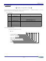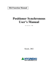
1
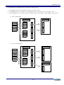
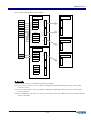
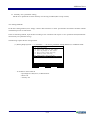
Hi4 Function Manual
Additional Axes
User's Manual
(Version 1.0)
March, 2002
Additional Axes
1. Introduction
This document is prepared to guide users to set servo controlled auxiliary axis as to the robot.
【 Registration procedure 】
■
Preparation
(1) Manipulator (Robot + Aux axis) and wire-harness
(2) Controller, auxiliary control unit or auxiliary servo amp, BD440 1set(in case of more than 3 aux
axes) and signal cables.
(3) Mechanical parameters for auxiliary axis
Input data according to registration format (Article 3.2): Assignment of auxiliary axis, axis spec and
configuration, bit constant, etc.
(4) Servo parameter for auxiliary axis
Register input data as to motor and encoder spec to auxiliary axis servo parameters in format shown article
3.3.
(5) Auxiliary axis acceleration/deceleration time
Prepare input data of auxiliary axis acceleration/deceleration time.
(System[PF2] - 3:Machine parameter - 6.Accel & Decel parameters )
■
Registration of Robot type and auxiliary axis parameters
After connection between controller and manipulator is carried out, initialize system.
Input robot type and number of auxiliary axis (= [ ])and mechanical parameters of auxiliary axis and servo
parameters.(Maximum auxiliary axis = 6 axis)
※ If these setting are set at the factory, don’t need to register the parameters.
■
Connectivity and Inspection
Turn the controller power Off-> Connect wire-harness between manipulator and controller->Turn the
power On-> Set encoder calibration and set robot reference position(axis constant) if necessary.
■
Completion
After setting auxiliary axis operation, store the ROBOT.C01 file with the external memory. (HRview,
PCcard)
2. Preparation
2.1. Check peripherals for the installation
2.2. Check data sheet for setting auxiliary axis.
(1) Mechanical constants of auxiliary axis
(2) Servo parameters on auxiliary axis
There are two methods in setting auxiliary axis servo parameter of Hi4 controller. For the first method,
refer to “3.Robot type and auxiliary axis mechanical constant registration” (recommended).
For the second method, refer to “ Attachment – auxiliary axis servo parameter individual setting”
(3) Auxiliary axis acceleration / deceleration
2/16
Additional Axes
2.3 Combinations of BD440 and servo AMP as to number of axis
1∼6 axes(default 6 axes robot) : BD440 :1 unit, 6 axis AMP: 1 unit
7∼8 axes(default 6 axes+ Auxiliary 2 axes): BD440:1unit, 6 axis AMP: 1unit +2 axis AMP: 1 unit
9∼12 axes(default 6 axes+ Auxiliary 6 axes) : BD440: 2 units, 6 axis AMP: 2 units, MSPR I/O in common
(1) 6 axes combination
1st BD440
Axis
1 DSP
1 axis
1servo
2 axis
2servo
3 axis
3servo
4 axis
4servo
5 axis
6 axis
2 DSP
6 axis AMP
C
N
B
S
1
C
N
B
S
1
C
N
B
S
2
C
N
B
S
2
1servo
2servo
3servo
4servo
C
N
B
S
3
(2) 7,8 axes combination
1st BD440
Axis
1 DSP
1 axis
1servo
2 axis
2servo
3 axis
3servo
4 axis
4servo
5 axis
6 axis
7 axis
8 axis
2 DSP
6 axis AMP
C
N
B
S
1
C
N
B
S
1
C
N
B
S
2
C
N
B
S
2
1servo
2servo
3servo
4servo
C
N
B
S
3
2 axis AMP
C
N
B
S
1
3/16
Additional Axes
(3) 9∼12 axes combination(recommended spec )
1st BD440
Axis
1 DSP
1 axis
1servo
2 axis
2servo
3 axis
3servo
4 axis
4servo
5 axis
6 axis
2 DSP
6 axis AMP
C
N
B
S
1
C
N
B
S
1
C
N
B
S
2
C
N
B
S
2
1servo
2servo
3servo
4servo
C
N
B
S
3
2nd BD440
1 DSP
7 axis
1servo
8 axis
2servo
9 axis
3servo
10 axis
4servo
11 axis
12 axis
2 DSP
6 axis AMP
C
N
B
S
1
C
N
B
S
1
C
N
B
S
2
C
N
B
S
2
1servo
2servo
3servo
4servo
C
N
B
S
3
◆【Note】◆
※ MSPR relay control signals (Input 1, Output 1) are commonly used as to the second 6 axis AMP .
※ Brake control in Hi4 controller consists of 6 axis board and 3 axis additional board, only 9axes can be controlled
respectively. Therefore, it is recommended that additional 3 axis board is commonly used for more than 10 axis
combination.
4/16
Additional Axes
(4) 9∼10 axis combination (the other example)
1st BD440
Axis
1 DSP
1 axis
1servo
2 axis
2servo
3 axis
3servo
4 axis
4servo
5 axis
6 axis
9 axis
2 DSP
7 axis
1servo
2servo
3servo
4servo
6 axis AMP
C
N
B
S
1
C
N
B
S
1
C
N
B
S
2
C
N
B
S
2
C
N
B
S
3
2 axis AMP
C
N
B
S
1
2nd BD440
1 DSP
8 axis
1servo
10 axis
2servo
C
N
B
S
1
2 axis AMP
3servo
4servo
2 DSP
1servo
2servo
3servo
4servo
C
N
B
S
2
C
N
B
S
2
C
N
B
S
3
◆【Note】◆
(1) Robot axes(6 axes) are set as default and can not be changed.
(2) 1st servo, 2nd servo and 3rd servo of 1st DSP in 1st Board are sequentially used for up to main 3 axis of robot.
(1st axis to 3rd axis)
(3) 1st servo, 2nd servo and 3rd servo of 2nd DSP in 1st Board are sequentially used for up to wrist 3 axis of robot.
(4st axis to 6rd axis)
(4) In case of HR100P( 4 axes robot ), 1st servo, 2nd servo and 3rd servo of 1st DSP and 1st servo 2nd DSP are used for
4 axes of robot links.
5/16
Additional Axes
3. Robot type and auxiliary axis mechanical constant registration
3.1. Setting robot type and auxiliary axis
14:39:38 *Robot type selection* A:0 S:1
1: HR120 (Matsushita motor)
2: HR150 (Matsushita motor)
3: HR150S
4: HR100P
5: HR120S
6: HR006-02 (without R2-cable cover)
7: HR006-03 (with R2-cable cover)
....
....
....
Use [Number]/[Up][Down] and press [SET].
>_
Previous Next
(1) Though selection of [PF2]"System" -> "5: Initialize" -> "2: Selecting type of the robot" in Manual
mode, select the type of robot and press [SET] key.
14:39:38 *Robot type selection* A:0 S:1
1: HR120 (Matsushita motor)
The number of additional axes = [1]
Conveyor synchronization = <OFF, ON>
Vibration control mode = <OFF, ON>
Enter number and press [SET]
>[0-6]_
Previous Next Execute
(2) Enter the number of auxiliary axis, press [PF5]“Execute” key to display following message in the
guide line.
14:39:38 *Robot type selection* A:0 S:1
Maker?
>[0-6]_
[YES][NO]
Previous Next
Execute
14:39:38 *Robot type selection* A:0 S:1
Set constants of additional axes? [Y/N]
>[0-6]_
Previous Next Execute
(3) As pressing [SET(YES)]key, the menu shown in item (2) of menu 3.2 is displayed.
6/16
Additional Axes
3.2. Auxiliary axis mechanical constant setting
(1) Select [PF2]"System" -> "5: System format" -> "21: Additional axes setting" in Manual mode.
14:39:38 *** System format *** A:0eS:1
1: System format
2: Selecting type of the robot
3: Setting usage of the robot
5: Positioner group setting
6: Endless axes setting
21: Additional axes setting
22: Servo parameter setting(Add-axis)
Use [Number]/[Up][Down] and press [SET].
>_
Previous Next
※ To be able to select item 21
- Input Engineer code( R314 ) in Manual mode
- Motors off
- Auxiliary axis
(2) Set auxiliary axis constant.( Max 6 axis )
14:39:38 *Additional Axis(1)* A:0eS:1
Axis position: BD=[1] DSP=[1] Axis=[4]
Application =<Travelling,Gun,Jig>
Joint pattern =<Nothing,X,Y,Z,Rxyz>
Bit constant
=[
0.00000]
Rated RPM
=[1000]
Max stroke
=[
1]
Enter number and press [SET]
>[1 - 2]_
Previous Next Complete
Press [PF5]"Complete" key for completion.
7/16
Additional Axes
◆【Description of Acuxiliary axis mechanical constant】◆
(1) Axis location : enables user to define physical configuration of auxiliary axis
BD =[1](1∼2)
=> Assign BD440 board No.( 2DSP/1Board )
DSP =[1](1∼2)
=> Assign DSP No. in BD440 board.( 4 axis/1DSP )
Axis =[4](1∼4)
=> Assign axis No..
Example) When1,1,4 is defined in order to set 7th auxiliary,
Default axis: 6 axis - Main 3 axis(BD440 No.1, DSP No.1, 1st ∼3rd axis )
Wrist 3 axis(BD440 No1, DSP No.2, 1st ∼3rd
axis)
th
Auxiliary 1 axes( BD440 No.1, DSP No.1, 4 axis )
(2) Specification of axis : Select one type of
auxiliary axis in < Travelling, Gun,Jig>.
When specification of auxiliary axis is defined,
according to logical sequence of auxiliary axis,
keep sequence of Travelling ->Gun->Jig must
to be maintained.
ZZ
X
XX
(3) Axis configuration : Select axis movement
direction in <Nothing,X,Y,Z,Rxyz>
In carriage type, if left/right axis is travel axis,
<X> is in movement, and if forward/backware
axis is travel axis in <Y> is in movement.
When the reference position of robot
manipulator is parallel to carriage axis in the
installation, select <Y>.
In GUN type, refer to servo gun guide. In JIG
type, refer to positioner synchronization
function guide
Robot
로봇본체
Travelling
주행축 Axis
Y
Y
HR 제어장치
HR300제어장치
Robot
Controller
(4) Bit constant[-9999.99999∼9999.9999] :
Axis movement for 1 pulse in encoder is registered as mm/10000bit.
If coordinate value is incremented as forward direction is in the same direction with the rotational
direction of reduction gear, sign to numeric value is “+”
For example, Motor at 100 turns, 1m is moved
Bit constant = 1000[mm] ÷ ( 100[rev] × 8192[bit/rev] ) = 0.0012207031.
It becomes 12.20703. as setting to 10000[bit]
(5) Rated RPM[1 - 5000] :
Information to set automatically the maximum speed of auxiliary axis motor in System[PF2] -> 3:
Machine parameter -> 6: Accel & Decel parameters
Normally Acceleration/Deceleration is assigned with the minimum value (Operator can modify the
setting by change the Accel time and)
(6) Max Stroke[1 - 30000] :
Information to set valid robot operation area( soft limit of auxiliary axis ) : System[PF2] -> 3:Machine
parameter-> 3: Software limit
8/16
Additional Axes
3.3. Auxiliary servo parameter setting
Set the servo parameter to meet auxiliary axis driving condition(Servo loop control)
Two setting methods:
In the first setting method, user simply collects data reference to motor specification and enters the data without
calculation process of each iterms.
In the second setting method, input the data according to user calculation with respect to servo parameter format(Attachmenteach auxiliary axis parameter setting)
The following explains the first setting method.
(1) Select [PF2]"System" -> "5: Initialize" -> "22: Servo parameter setting(Add-axis)" in Manual mode.
14:39:38 *** System format *** A:0eS:1
1: System format
2: Selecting type of the robot
3: Setting usage of the robot
5: Positioner group setting
6: Endless axes setting
21: Additional axes setting
22: Servo parameter setting(Add-axis)
Use [Number]/[Up][Down] and press [SET].
>_
Previous Next
※ To be able to select item 22
- Input Engineer code( R314 ) in Manual mode
- Motors off
- Auxiliary axis
9/16
Additional Axes
(2) Set auxiliary axis servo parameter.(Maximum 6 axis )
14:39:38*Add-axis servo PRM-1Ax* A:0eS:1
Encoder type
=<0,1,2,3>
Encoder pulse
=<1024,2048,4096,8192>
Direction of rotation
=<CCW,CW>
Phase shift at zero
=[ 30]deg
Number of Poles
=<2,4,6,8>
Lead signal at CCW rotation
=<A,B>
Momentary max. current[peak]=[ 84.85]A
Stall current
[peak]=[ 32.08]A
AMP type
=<Mini,Larg>
Maximum current of AMP
=[ 93.75]A
Press [SHIFT]+[<-][->] key.
>_
Previous Next Complete
Upon the completion, press [PF5]"Complete" key.
◆【Auxiliary servo parameter】◆
※ Be informed that the following data can be changed according to design modification from manufacturer
※ According to load condition, after setting each item,
[PF2]"System" -> "3: Machine parameter" ->
acceleration & deceleration parameters of "6: Accel & Decel parameters"의 and [PF2]"System" -> "3:
Machine parameter" -> "12: Servo parameter setting" -> "1: Servo loop gain" Kp(positional gain) and
Kv(velocity gain). shall be adjusted in use
(1) Encoder type
0 : Yaskawa, 1 : Tamakawa, 2 : Panasonic, 3 : Panasonic Compact type
HR controller can only provide absolute encoder
Select encoder according to maker’s spec
(2) Encoder pulse
< 1024, 2048, 4096, 8192 >
Number of encoder pulse in single rotation of motor.
In general, Yaskawa 12bit encoder :1024, Yaskawa 15bit Encoder: 8192, Panasoni : 2048, Tamagawa: 4096.
(3) Direction of rotation
< CCW, CW >
Enter the CW direction of motor.
Rotation direction is incremental direction in encoder position when motor is viewed at the side of motor shaft
When encoder value in increased as rotating in CCW, it will be CCW. When encoder value is increased as
rotating in CW, it will be CW.
In general, Yaskawa and Tamagawa and Panasonic are all in CCW.
(4) Phase shift at zero
θ [deg]
Input current phase angle at 0 position of encoder .
In general, Yaskawa and Tamagawa: 0, Panasonic: 30.
(5) Number of poles
< 2, 4, 6, 8 >
Enter number of poles in motor.
(6) Incremental Encoder lead phase at CCW
< A phase, B phase >
10/16
Additional Axes
When shaft rotates in CCW direction at the front view of motor, input lead phase either in A phase or B phase in
incremental output value of encoder.
In general, A phase leads in Tamagawa motor and B phase leads in Yaskawa and Panasonic motor.
(7) Momentary max current
Ip [Apeak]
Peak current to be resulted in motor must be input with peak value not rms value.
Enter the current value in reference to load calculation of auxiliary axis manipulator.
Setting value shall be lower than the maximum peak current and not be over 95% of the maximum current of AMP.
(8) Stall current
Is [Apeak]
Input stall current of motor as Peak. If it is not shown in spec data sheet, input rated current as peak. However the
current value must be less than current peak current.
(9) Maximum current of AMP
Iamp [Apeak]
Set maximum current of AMP Unit. The maximum current is refer to ‘Amp Maximum Current’ in Attachment
◆【Note】◆
1) When Travelling axis, GUN, JIG axis are to be set at the same time, register Travelling axis first, GUN axis
second, JIG axis last in sequence order.
11/16
Additional Axes
4. Connection and Inspection
4.1. Connect all cables and supply power to the controller. If servo error is occurred at initial self
diagnoses stage, check servo parameters that are entered correctly according to the specification. And
check encoder line with the reference to Hi4 controller maintenance manual and signal connection. .
4.2. Check current setting axis.
Select [PF1]“Service" -> "7: System checking" -> "1: System version".
14:39:38 ** System version ** A:0eS:1
Robot type: HR120
(Axis: 6 Tot Ax: 8)
Main System Version => Robot Language
Main S/W: V10.00-15 2002-03-15
Motion S/W: V07.05
2002-03-21
T/P ver : V01.03
1999-05-31
I/O ver : V00.00
0-00-00
DSP Version
DSP1 S/W: V99.99
2000-12-31
DSP2 S/W: V99.99
2000-12-31
DSP3 S/W: V00.00
0-00-00
0-00-00
DSP4 S/W: V00.00
Press [ESC] or [R..]
>_
Previous Next
※ Axis : robot axis,
Tot Ax : robot axis + additional axis.
4.3. Set reference position of encoder by selecting [PF2]"System" -> "3: machine parameter" -> "5: Setting
encoder offset". Make encoder value 0x400000 at the reference position of each axis.
4.4. Select [PF1]"Service" -> "1: Monitoring" -> "1: Axis data", press [SHIFT]+[×] key to check
0x400000 in each axis data and press Motors ON.
14:39:38 *** M A N U A L *** A:0eS:1
T0
PN:001[*]__ S/F=2/1
Sp:500
S2 MOVE L,S=500mm/sec,A=0,T=0
DO25=1
Current Command
Angle Coord(mm)
V :400000 400000
0.0deg X=
0.0
R2:400000 400000
0.0deg Y=
1725.0
B :400000 400000
0.0deg Z= 2090.0
R1:400000 400000
0.0deg RX=
0.0
0.0
T1:400000 400000
0.0mm Ry=
Press [ESC] or [R..]
>_
Previous Next
※ Axis data of T1,T2 on the screen is the distance from the origin of auxiliary axis on robot coordinate system.
In case of traveling axis,
coordinate value(X,Y,Z) = Auxiliary coordinate value(X1,Y1,Z1) + Robot coordinate value(X2,Y2,Z2).
In monitoring screen, check encoder(command/current value) changes according to direction, with
manual JOG movement, to forward/backward direction in each axis
Start with low speed at the initial manual operation. If there is no movement at current value, check
brake release.
4.6. Check acceleration/deceleration parameters and bit constant. In order to protect main components in
manipulator, acceleration /deceleration time must be set with respect to mechanical data.
Bit constant should be checked by comparison of monitoring distance value and measured distance
of auxiliary axis.
4.7. Check soft limit and set it if necessary. Check input state of hardware limit.
4.5.
12/16
Additional Axes
4.8. During manual speed and auto operation, if vibration and shaking is occured, check mechanical
assembly and tuning parameters(acceleration/deceleration, servo loop gain).
5. Completion
Upon the completion of auxiliary axis setting copy Constant file(ROBOT.C00, ROBOT.C01) to external memory
devices (HRview, PC card) via selecting [PF1]"Service" - "5: File manager" - "5: copy"
6. Jogging & Running
6.1. Jogging
(1) If pressing [AUX AXIS] key in Teach Pendant, LED blinks. If pressing [LFT/(S+)], [RHT(S-)] key,
manual operation for first auxiliary axis can be carried out.
(2) When LED of AUX AXIS blinks, only auxiliary axis is operated.
(3) Operation according to status of [COORD]key is as follows.
- JOINT, CART : Auxiliary axis in general operation(Move to setting axis direction )
- TOOL : Position of tool center point is not changed in moving traveling axis
(5) (TCP) coordinate value(X,Y,Z) = Auxiliary coordinate(X1,Y1,Z1) + Robot coordinate(X2,Y2,Z2)
(6) Manual operation speed( S8 speed level ) : 25% of Maximum speed of auxiliary axis
(Limit within max 250mm/sec)
(7) Move direction of Auxiliary axis follows user coordinate in user coordinate system.
6.2. Running
(1) Interpolation Off
Each axis reaches simultaneously to target point .
(2) Linear Interpolation
Linear interpolation movement(trajectory, pose) of target point is executed.
(3) Circular Interpolation
Circular interpolation movement of target point is executed.
(4) Shift
Functions (Offline, Online, Search, Palletizing)for shift applies only to robot and
auxiliary axis moves only to the recorded position
Specially, in search function, auxiliary axis must not be in movement in search operation step.
(5) Coordinated conversion
Movement of auxiliary axis in original program must not have any changes because coordinated
conversion converts only movement disposition as to robot and transfers target value of auxiliary axis in
the same value.
(6) Relative program call function
Do not move auxiliary axis in programming relative program..
It only applies relative position as to robot.
13/16
Additional Axes
7. Troubleshooting
1. E0103 ∼ E0108
Contents
Countermeasure
Encoder and manipulator wiring and connection
Hi4 controller maintenance manual
abnormal
Error
Message
Contents
Countermeasure
14/16
Additional Axes
♠
Attachment ♠
◆ Auxiliary servo parameter setting ◆
In manual mode, enter engineering code( 'R314') to enter [PF2]"System" -> "3: Machine parameter" -> "12: Servo
parameter setting"to set servo parameter of auxiliary axis.
1. Servo loop gain
Parameter
Contents
Setting methods
Kp
Position loop proportional gain
Generally setting is identical to 1st axis
Kf
FeedForward gain
Kv
Speed loop proportional gain
0
Kb
Speed Feedback constant
Generally setting is identical to 1st axis
Ki
Speed loop Integral gain
Generally setting is identical to 1st axis
F1
1st Filter time constant
Generally setting is identical to 1st axis
F2
2nd Filter time constant
Generally setting is identical to 1st axis
Fc
Filter coefficient
Generally setting is identical to 1st axis
Generally setting is identical to 1st axis. Adjust when vibration is occured
Im
AMP peak current
Ip
Setting Peak current
Momentary maximum peak current of motor[Apeak]x100
Peak current of auxiliary AMP[Apeak]x100
Ir
MOTOR Continuous current
Continuous current of motor[Apeak]x100
Ti
MOTOR Overload time constant
16
Note1) AMP maximum current
Set Auxiliary AMP numbering for setting.
■
Type ;
HD □ □ □ - □ □ - □ □ □ □
HYUNDAI DRIVER
IPM Capacity - Main3axis
- Wrist3axis
6Axis / 2Axis
Shunt resistor - Main 3axis(Aux1 axis)
(Medium AMP) - Wrist 3axis(Aux2 axis)
Year
Month
Serial no
15/16
- xxx
Additional Axes
Medium AMP is defined with respect to Shunt resistor value .
Shunt resistor(mark in case of medium Drive Unit only)
2 mΩ
4 mΩ
8 mΩ
12 mΩ
16 mΩ
1
2
3
4
5
Shunt
resistor
mark
: 93.75Apeak
: 46.87Apeak
: 23.44Apeak
: 15.58Apeak
: 11.72Apeak
Small AMP is defined with respect to Hall Sensor.
Small AMP
IPM
Capacity
mark
A
(IPM Rated current) 30A, (Hall Sensor Rated current) 4V/15A : 28.12Apeak
B
(IPM Rated current) 20A, (Hall Sensor Rated current) 4V/10A : 18.75Apeak
C
(IPM Rated current) 15A, (Hall Sensor Rated current) 4V/10A : 14.06Apeak
D
(IPM Rated current) 10A, (Hall Sensor Rated current) 4V/5A
: 9.37Apeak
2. Position error level
Setting value : Deviation value to detect positional deviation error
Measured value : The maximum positional deviation value that has been occurred from the start of controller power
on to present state. Normally setting value is set as 1.2 times to 1.5 times of measured value
3. Motor and encoder type
Decide according to motor and encoder spec.
Parameter
Contents
Setting method
S1
Rotation direction of Motor
If forward direction is in CCW, select 0, and CW, select 1
S2
Number of Pole in Motor
Motor Pole no. / 2
S3
Absolute encoder data format
1-Yaskawa, 2-Tamagawa, 3-Panasonic, 7-Pannasonic Compact Encoder type
S4
Direction in Incremental pulse
In CCW rotation of motor, 0 if A phase leads , 1 if B phase leads
S5
Encoder expansion
0- Standard, 1- Tamagawa Even, 2- Tamagawa 21bitEven, 3- Tamagawa 21bitOdd
PULS
Number of Encoder Pulse
PHSE
Crrent phase angle at Zero
0° ∼ 359° , Normally Pannasonic:30°
1024,
2048,
4096,
8192
PHVL
Current delay compensation due
to speed( at 2000rpm)
0° ∼ 359° , In general 10° ∼40°
4. Current loop gain
(1) Set according AMP capacity to be used.
(2) Setting value
Parameter
Contents
Setting method
Medium AMP
Small AMP
C11
Current Interrupt Lag
[ 0∼1 ] 0:0%, 1:5%
0
0
C12
Current Loop
[ 0∼1 ] 0:Disable, 1:Enable
1
1
C13
Current Loop Gain
[ 0∼7 ]
5
5
C14
Current Loop time constant
[ 0∼7 ]
5
5
C15
Filter
[ 0∼1 ] 0:Enable, 1:Disable
0
0
C16
Filter selection
[ 0∼3 ] 0-1/8, 1-1/4, 2-1/2, 3-1/1
3
3
C21
PWM On Delay
[ 0∼15 ]
15
9
C22
PWM Carrier Frequency
[ 0∼15 ]
13
13
C31
Reserved
0
0
5. Vibration control gain
Ignored in auxiliary axis.
6. Servo data setting for 2 axes sync
Ignored in auxiliary axis.
16/16