1
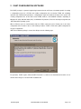
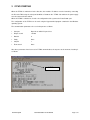
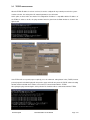
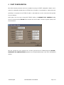
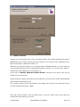
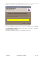
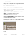
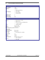
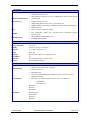
The Z-PC System
Quick Start Guide
TABLE OF CONTENTS
1 THE Z-PC SYSTEM….…………………………………………………………………………3
1.1
DESCRIPTION………………………………………………………………………………….3
1.2
THE Z-TWS MODULE…………………………………………………………………………3
1.3
I/O MODULES…………………………………………………………………………………4
2 Z-NET CONFIGURATION SOFTWARE……………………………………………………..5
3 SWITCHING ON THE Z-TWS..………………………………………………………………..6
3.1
TCP/IP CONFIGURATION..……………………………………………………………………7
4 Z-NET CONFIGURATION..……………………………………………………………………8
4.1
MODULE INSERTION………………………………………………………………………..…9
4.2
CONFIGURATION FILES………………………………………………………………...11
ENCLOSURES
A. Z-TWS CONNECTIONS..…………………………………………………………………….....13
B. Z-TWS TECHNICAL SPECIFICATIONS.…………………………………………………………14
The Z-PC System
Quick Start Guide rev.1.00 28.04.04
Page 2 / 15
1 THE Z-PC SYSTEM
1.1
DESCRIPTION
The Z-PC Series is a line of components for the automation and control of industrial processes that offers a
solution for the automation of small to medium size machines and systems.
Integrated, compact and reliable, Z-PC modules permit the acquisition of practically all types of industrial I/O
and processing and transformation towards computerised supervision and control systems
(ethernet,
internet, LAN, VPN, etc.). The variety of the modules designed permits the management of all types of I/O,
serial interface (RS232 / 485 ), filers, counters, PID regulation and even remote-control via WEB. Z-PC
modules based on Modbus RTU communication protocol are protected by galvanic separation between the
signal and power line and offer the ideal solutions in numerous applications such as the remote control of
utilities, remote civil and industrial measurement, building management, and the automation of non-critical
industrial processes. All this is achieved efficiently and economically..
1.2
THE Z-TWS
MODULE
The Z-TWS module represents the latest state-of-the-art in the field of web automation. Despite its compact
dimensions, the Z-TWS is equipped with a RS485 serial port for peripheral data exchange, two RS232
interface ports, and an ethernet link open to the remote connection and supervision networks. Last but not
least, the Z-TWS is compatible with the all the leading office automation standards.
With as many as 4 functional modules housed on just one single platform, the Z-TWS is a combined
PLC/Tiny Web Server module oriented towards technological concentration.
An advanced performance controller equipped with a 32-bit RISC microprocessor for small and medium size
automation is more than capable of replacing the PLC usually adopted, while a built-in web server ensured
by resident memory capacity (16 MB Flash and 8 MB Ram) provides for supervision and remote-control and
assistance (resetting, parameter variation and maintenance) because the ethernet port permits the system or
machine to be interfaced with the company's own LAN with monitoring and/or control functions, and by
means of an appropriate router (external), the system can also be remote-accessed (internet ). Also included
is a data logger for trend management and the memorisation of the development over time of system signals
and/or status that can be subsequently used for analysis and checking operations. Lastly, a RTU (Remote
Terminal Unit), in other words, a device capable of acquiring data and making them available for remotecontrol thanks to the use of the most commonly-available communication standards has been provided.
The Z-PC System
Quick Start Guide rev.1.00 28.04.04
Page 3 / 15
1.3
I/O MODULES
The Z-PC Series is composed of a set of 5- and 10-modularity instruments for the management of digital
inputs and outputs that are digitalised and converted on serial protocol.
The Z-PC I/O modules are slaves to Modbus RTU masters that manage errors and malfunctions and offer
safety statuses. Digital
modules permit the acquisition of almost all types of contacts coming from
pushbuttons, limit-switches, contactors, relay, proximity switches and alarms. The modules are provided with
opto-insulation between the input and the remaining low voltage circuits. The presence of 16- or 32-bit
counters permits the setting of one or two quick counters with 10 kHz frequency. The latter are used for the
piloting of 5 or 10 SPST relays for drives, alarms, luminous signalling devices, contactors and other users.
Universal voltage, current, Ohm, thermocouple and heating element inputs from transducers, sensors and
analysers can be interfaced with the various multi-input analogue modules.
The analogue series is completed by the PID regulator and the output adjustment module. The possibility to
provide power supply for transducers, opto-insulation, elevated software configuration capacity, floating point
arithmetic and the presence of microprocessors all make the Z-PC analogue I/O modules sturdy, reliable,
high-precision, instruments. The complete range includes: Z-D-IN (5 digital inputs) , Z-D-OUT (5 digital
outputs), Z-10-D-IN (10 digital inputs), Z-10-D-OUT (10 digital outputs), Z-DAQ (universal analogue output),
Z-4TC (4 inputs per thermocouples), Z-4RTD (4 inputs for heating elements), Z-4AI ( 4 V or I inputs), Z-PID
(analogue IN / OUT with PID regulation functions), Z-3AO (3 analogue outputs).The Z-PC series also offers
serial converters and radio modems to guarantee the necessary coverage of the needs for data exchange
between system nodes.
Also available in back panel and portable versions (S107 and S107P ), the RS232/RS485-422 converters
connect I/O and therefore the field bus to the data concentration and control device. Thanks to half/full
duplex operation and automatic direction change, the converters can cover distances of up to 1,200 meters
with transmission speeds from 9600 to 115,200 bps. The receiver-transmitter modules (Z-LINK and S-LINK
) based on UHF radio modem (100 KBps, 434-868 mHz, 10 mW ) permit communication between the Z-PC
Series modules through ModBUS protocol.
Without managing any transmission control, the receiver-transmitter module automatically memorises the
data received and transmits such data through dialogue with all the nodes linked in the network.
The Z-PC System
Quick Start Guide rev.1.00 28.04.04
Page 4 / 15
2 Z-NET CONFIGURATION SOFTWARE
The Z-NET package is a powerful engineering instrument based on IEC 61131 Standard capable of creating
a configuration project for a Z-TWS unit, reading configuration from an existing Z-TWS unit, modifying
operation and communication parameters, configuring the single I/O modules that compose the system, and
creating configuration files for the OPC Server ZTWS, Movicon, and ISAGRAF variables. Operating on
Windows NT (SP4), Windows 2000 (SP1), and Windows XP platforms, Z-Net was developed using Microsoft
.NET Framework operating system.
With an Ethernet port for communication with the Z-TWS central unit and a RS232 port for the direct
configuration of the modules or the use of the Debug Terminal, Z-NET is Z-PC Series global configurator for
any type of application.
When the installation package is started, the SW presents the following page:
For operation, Z-NET requires Microsoft.NET Framework 1.1, which can be downloaded from either one of
the links in the image or from the Z-NET installation CD.
The Z-PC System
Quick Start Guide rev.1.00 28.04.04
Page 5 / 15
3 Z-TWS STARTING
When the Z-TWS is switched on for the first time, the module's IP address must be learned by connecting
the PC to the TWS using the serial port identified as Port#0 on the Z-TWS side and then the power supply
must be connected to the module.
When the Z-TWS is switched on, it sends the configuration of the system to the Porta Port#0 port.
The configuration of the Z-TWS can be read using the Hyperterminal program contained in the Windows
operating system.
The communication parameters to be set for the port are as follows:
•
Com port
Depends on which PC port is free
•
Bit per second
115200
•
Data bit
8
•
Parity
None
•
Stop bit
1
•
Flow control
None
After these parameters have been set for Z-TWS communication, the response at the moment of starting is
as follows:
IP TWS
The Z-PC System
Quick Start Guide rev.1.00 28.04.04
Page 6 / 15
3.1
TCP/IP
CONFIGURATION
After the Z-TWS IP address has been received, it must be configured in any network present in the system..
In order to do this, the setting of the PC network parameters must be known.
At this point, we must make sure that the PC configuration IP address is compatible with the IP address of
the Z-TWS; in order to do this, the ping command must be given from the DOS window as shown in the
figure below
If the Z-TWS fails to respond (request expired), press the advanced setting button in the (TCP/IP) internet
protocol properties window displayed in the previous page and in this way enter the TCP/IP advanced setting
window and then add both the IP address and a mask for communication with the Z-TWS.
After giving the ping command again, at this point the PC should be able to communicate with the Z-TWS
The Z-PC System
Quick Start Guide rev.1.00 28.04.04
Page 7 / 15
4 Z-NET CONFIGURATION
After all the network parameters have been configured correctly, the Z-NET configuration software can be
started. As configuration default value, the Z-TWS has an IP address of 192.168.90.101, and therefore after
generating a new project the new Z-TWS IP address (192.168.90.101) must be entered and the operation
must be confirmed.
At this point, if it is necessary to change the Z-TWS IP address, the CHANGE TCP/IP ADDRESS heading
must be selected from the ON LINE menu and then the new IP address and the respective subnet mask
must be entered
After this operation has been performed, the new files generated in the Z-TWS through the ON-LINE |
DOWNLOAD TWS CONFIGURATION operation must be downloaded and the result of the file download
awaited.
The Z-PC System
Quick Start Guide rev.1.00 28.04.04
Page 8 / 15
4.1
MODULE INSERTION
In order to insert new modules in the system, the module's address and communication baud rate written in
EEPROM must first be known. The first time that the modules are used, they must be supplied by Seneca
with a default setting of 38400 and an address of 1.
Whenever it is impossible to gain access to the data written in EEPROM, dipswitch 1 on the module side
must be modified and then the fixed communication parameters must be set, or in other words, address 1
and baud rate equal to 9600 bits per second must be set.
At this point, the MODULE INSERTION WIZARD PROJECT command can be given to add any new
modules to the system desired.
Indicate the project's initial speed and final speed and then press Proceed, and the Z-NET will automatically
change module communication speed.
The next page requires the entry of the Modbus for the module to be inserted (1, if the dip switch has been
set in the fixed parameter position 1-9600).
At this point, enter the address of the new module (leave 1 as the free address for the entry of other new
modules required) and then press Proceed.
The Z-PC System
Quick Start Guide rev.1.00 28.04.04
Page 9 / 15
Remember to switch the address selection dipswitch OFF after the module has been inserted, and in order
to permit correct communication, repeat the steps above for the insertion of other modules.
The error I/O window displays any system configuration errors that have occurred. .
After correctly configuring all the modules, the necessary data must be downloaded by giving the ON LINE |
TWS CONFIGURATION DOWNLOAD command, and in this way the files required for correct system
configuration will be coped in the Z-TWS.
At this point, the system has been configured correctly and the Z-TWS can be used.
The Z-PC System
Quick Start Guide rev.1.00 28.04.04
Page 10 / 15
4.2
CONFIGURATION FILES
In addition to configuring and saving the settings for the Z-TWS and the modules connected, the Z-Net
software permits the generation of the support files required for other applications such as ISAGRAF, OPC
server, and Movicon… that facilitate the interface of these programs with the Z-TWS
The main configuration files generated by the Z-TWS are:
•
TWS.ini
•
The file is contained in the main directory.
•
PLC.ini
Parameters for the initialisation of the TWS operating system and automatic processes.
Parameters for the initialisation of the RS485 serial communication module with MODBUS-
RTU protocol (contained in the main directory).
•
VARS.ini
Parameters for data-logger function configuration (contained in the main directory).
•
PASS.INI
Login and password for access to various system functions (contained in the /ETC/PPP
directory).
•
OPTIONS PPP connection configuration (contained in the main directory).
•
CHAP-SECRETS Login and Password for remote access via PPP.
•
The file is contained in the /ETC/PPP directory.
In addition, the FILE | GENERA FILE ISAGRAF control can be used to generate files for the display of the
connections to the IO Modbus modules in the Isagraf program.
The file OPC.INI contains the information necessary to define the variables to be displayed and monitored
by the SENECA OPC server.
The Z-NET permits the export of the variables defined in the modules or on the TWS as xml configuration
files for a Movicon project that uses l’OPC Server ZTWS for access to the modules.
In order to add headings to the files generated, the headings for the file in questions must be checked (e.g.
in the OPC box for OPC file generation, in the IsaGraf box for IsaGraf file generation, in the Movicon box for
Movicon files).
The Z-PC System
Quick Start Guide rev.1.00 28.04.04
Page 11 / 15
ENCLOSURES
The Z-PC System
Quick Start Guide rev.1.00 28.04.04
Page 12 / 15
A.
Z-TWS CONNECTIONS
POWER SUPPLY
The power supply voltage must remain in the range of either 19 and 40V DC
(any polarity), or 19 and 28V AC.
The upper limits must not be exceeded in
order to avoid serious risk to the module. The power supply source must be
protected from the malfunctions of the module through appropriately-sized safety
fuses.
SERIAL INTERFACE
The Z-PC System
Quick Start Guide rev.1.00 28.04.04
Page 13 / 15
B.
Z-TWS TECHNICAL SPECIFICATIONS
ELECTRICAL
Power supply
19 – 40 Vdc / 19 – 28 Vac / 50-60 Hz
Max. Absorption
3,5 W
Insulation
1.500 Vac
Ethernet transmission
Power supply
Status indicators
PLC in operation
No ethernet link
Installation class
II
Pollution rating
2
Protection rating
IP20
COMMUNICATION, PROCESSING, MEMORY
RS485
Ethernet 10Base-T-TCP/IP
Interface
RS232 user free
RS232 programming and debugging (PLC)
< 57600 bps (RS485)
Speed
10 Mb/s (ethernet)
Parity
None, even, odd
Protocol
ModBUS RTU slave
Binary instruction cycle time 2,5 ms/Kistruz.
Sampling time
-
Connection distance
Up to 1200 m
Connectivity
Max 32 nodes
CPU P RISC 32 bit – 20 MIPS
Processing
Floating point
yes
Timers
16.000
Counters
16.000
Special functions
Data logger, RTU, web server
Memory
The Z-PC System
Flash: 16 MB (data)
RAM: 8 MB
Quick Start Guide rev.1.00 28.04.04
Page 14 / 15
SOFTWARE
Ethernet
PPP (Point to Point Protocol)
HTTP (HyperText Transfer Protocol) for reading/writing variables and files through
Comunication Network and
TCP/IP network
Sistema Protocol
FTP (File Transfer Protocol)
SMTP (Simple Mail Transfer Protocol ) e-mail output server
ModBUS –ModBUS RTU Master (on RS485 port) / Master-Slave (on RS232 ports)
ModBUS TCP / IP
System & project configuration software
Z-Net
PLC programmino (ladder, Flux, sequential blocks, Structured Language,
IsAGRAF
instruction List)
Standard OPC Foundation Data Access 2
Z-TWS OPC Server
Compatible with all SCADA
TERMOMECCANICHE
Funcioning temperature
0..+55 °C
Storage temperature
-20..+70 °C
Humidity
30 / 90% a +40 °C (not condensino)
Dimension
17,5 x 100 x 112 mm (b x h x p)
Weight
250 g circa
Packaging
Nylon 6 with 30% glass fiber–estinguish class V0
Hot swapping
yes
Connection
Screw terminals, plug in for cable 2.5 mm
Mounting
35 mm DIN 46277 rail guide
2
CONFIGURAZIONI E NORME
PLC (ISAGRAF standard IEC1131)
SW Programming
Web server: supervision, control, browsing
Remote Telecontrol
Datalogger trend
32 devices due to RS485 limitation. Additional 32 devices with one (or more)
RS485 Bus Repeater.
I/O Configuration
Max number of variables to obtain a clicle less than 1 sec (900 msec).
o
500 Digital I/O
o
120 Analogo I/O
EN50081-2
EN 55011
EN 50082-2
CE Standard
EN 61000-2-2/4
EN 50140/141
EN 61010-1
EN 60742
The Z-PC System
Quick Start Guide rev.1.00 28.04.04
Page 15 / 15