1
Saturnus 8
NL-8448 CC Heerenveen
Postbus 219
NL-8440 AE Heerenveen
T. +31(0)513 656500
F. +31(0)513 656501
open flue built-in fireplaces
SILVA B11
SPECTRA B11
installation guide and user manual
40 010 535
03 35
3. INSTALLATION REQUIREMENTS
3.1 Builders opening and surround
3.2 Flue requirements
2. SAFETY AND GENERAL INFORMATION
2.1 General safety
1. INTRODUCTION
10
10
11
13
16
5
5
8
3
3
2
UK/IRL
4. INSTRUCTIONS FOR INSTALLATION
4.1 Gas connection
4.2 Preparing the appliance
4.3 Fitting the firebox
4.4 Placing the log set
19
19
19
CONTENTS
5. REMOTE CONTROL
5.1 Remote control
5.2 Installation remote control
8.1 Routine annual servicing
7. HANDING OVER
33
25
25
24
21
21
21
22
22
23
8. SERVICING
USER GUIDE
34
34
Check pilot ignition
Functional burner check
Spillage test
Flame Supervision & Blocked Flue Monitoring System
Check reference pressure
9. SAFETY INSTRUCTIONS FOR THE USER
9.1 General safety instructions
36
36
37
38
38
6. COMMISIONING
6.1
6.2
6.3
6.4
6.5
10. CONTROLING THE APPLIANCE
10.1 Lighting the fire
10.2 To light
10.3 To estinguish
10.4 Remote control version
42
31
11. CLEANING AND SERVICE INSTRUCTIONS
LIST OF SPARE PARTS
32
43
INDEX 1
TECHNICAL DATA
12. DISPOSAL OF THE PACKAGING AND THE APPLIANCE
INDEX 2
1
UK/IRL
2
2. SAFETY AND GENERAL
INFORMATION
UK/IRL
Before installation, ensure that the local distribution conditions
(identification of the type gas and pressure) and the adjustment of
the appliance are compatible.
1. INTRODUCTION
Note: these instructions should be read carefully and retained for
future reference.
Please leave these instructions with the user.
This gas appliance is factory set and shall not be adjusted by the
installer.
BS5440 Parts 1&2
BS8303
BS1251
BS715
BS5871 Part1
It is the law in the UK that all gas appliances, are installed by a
competent person in accordance with the Gas Safety (Installation and
Use) Regulations (As amended), the relevant British Standards for
Installation work, Building Regulations, Codes of Practice and the
manufacturers instructions.
The installation should also be carried out in accordance with the
following where relevant;
2.1 General safety
This appliance does not contain any component manufactured from
asbestos or any asbestos related products.
The spillage monitoring system must not be put out of operation.
This guide is concerning the following types of appliances:
SILVA
SPECTRA with flatfiber burner
SPECTRA with log burner
Special features:
- Realistic flame and glow effect.
- Small flue outlet, 100 mm.
- Remote Control option on all appliances.
- A spillage monitoring system (TTB switch) is fitted which cuts off
the gas if flue is blocked or malfunctioning.
- Meets the essential requirements of the European Gas Appliance
Directive (GAD) and carries the CE mark.
BS6891
Building Regulations Document J (as applicable).
3
UK/IRL
4
Building Regulations and Standards issued as relevant by the
Department of the Environment or the Scottish Development
Department.
In the Republic of Ireland installation should be carried out in
accordance with IS813, ICP3, IS327, Building Regulations, Codes of
Practice, the manufacturers instructions and any other rules in force.
Failure to comply with the above could leave the installer liable to
prosecution and invalidate the appliance warranty.
The appliance must not be installed in a room containing a bath or
shower or where steam may be present.
Ventilation
No purpose provided ventilation is normally required when this
appliance is installed in the UK. Where other appliances operate in
the same room or space then these should be considered when
sizing air vents. The spillage test in the section commissioning may
indicate that purpose provided ventilation is required. Where fitted
ventilation must comply with BS5440 part 2. For the Republic of
Ireland the ventilation requirements may vary and if unsure then
advice should be sought from the relevant authorities.
Safety instructions for the user: see chapter 9.
UK/IRL
3. INSTALLATION REQUIREMENTS
Note:
Since the appliance is a source of heat, circulation of air occurs.
Therefore it is of importance that you do not use the appliance
shortly after a renovation of the home. Because of the natural
circulation of air, moist and volatile components from paint, building
materials, carpet etc. will be attracted. These components can settle
themselves down onto cold surfaces in the form of soot.
As on all heat producing appliances, soft furnishings such as blown
vinyl wallpaper placed too near to the appliance may become
scorched or discoloured. This should be born in mind when installing
the appliance.
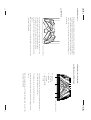
3.1 Builders opening and surround
The appliance can be installed in the following situations:
In a non-combustible fireplace or builders opening. This could be
either an existing builders opening or a new made prefab builders
opening. For the measurements, see figure 1 and index.
Although the appliance is tested for installation without a hearth, the
appliance must not stand on combustible materials or carpets. If the
appliance is placed on a combustible floor then a fibrelux or similar
heatproof board of 12 mm thickness should be placed under it. Any
under floor vents or openings within the builders opening should be
sealed off.
Do not place the lintel, surround or marble stone directly onto the
appliance. If possible, apply a lintel made of cement or something
similar.
5
UK/IRL
- Side clearance = Minimum distance from the side of the fire frame
to combustible material = 150 mm.
- If the shelf depth is greater than 150 mm add 50 mm to the shelfclearance height for every 25 mm increase in shelf depth.
- For a shelf up to 150 mm deep – Minimum height = 350 mm
(fig. 1).
The minimum height from the top surface of the fire to the underside
of any shelf made from wood or other combustible materials is as
follows:
If the appliance is to be fitted against a wall with combustible
cladding, the cladding must be removed from the area covered by the
surround.
- The plaster of the outside has to be resistant to a high
temperature. Use therefore the plaster materials especially made for
this such as Masterboard or Fibrelux, to prevent discoloring (min.
100 degrees temperature resistant).
- Always supply the appliance with a DC convection set.
- Ventilate the space above the appliance (min. 1000 mm2).
If the builders' opening is constructed of anything other than brick
e.g. stud work and rendered plaster then:
3.1 Builders opening and surround (continuing)
6
C
B
D
E
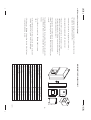
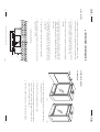
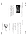
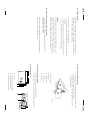
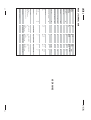
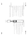
Builders opening (mm)
Opening width
Opening height
Opening depth (min.)
Shelf dimensions (combustible)
Min. height shelf from top frame
Depth shelf max.
Dimensions (mm)
Box width
Box depth
Box height
Frame width
Frame height
Frame thickness
Position flue (behind frame)
Position flue (from the back side box)
A
MEASUREMENTS BUILT IN AND APPLIANCE
A
B
C
D
E
F
G
H
I
J
K
L
M
F
G
K
Silva
600
715
370
350
150
Spectra
770
710
410
I
350
150
755
361
695
790
720
23
262
99
J
578
324
700
629
727
15
235
89
L
M
H
UK/IRL
fig. 1
table 1
7
UK/IRL
When installing a flexible flue liner, it must be fully contained within
another flue and properly supported.
If the appliance is intended to be installed to a chimney which was
previously used for solid fuel, the flue must be swept clean prior to
installation. All flues should be inspected for soundness and freedom
from blockages.
The minimum effective height of the flue system must be 3 meters.
The flue, most have a positive updraught.
The flue must not be used for any other appliance or application.
Any chimney damper or restrictor should be removed. If removal is
not possible, they must be secured in the fully open position.
1. flexible stainless-steel liner or pipe (to BS715). The flue connector
outer collar is for connection to a 125 mm (5 inch) internal
diameter pipe or liner. The inner collar is for connection to a
100 mm internal diameter pipe or liner.
2. min. 100 - max. 150 mm factory made insulated flue manufactured
to BS 4543.
3. max. 225 mm x 255 mm conventional brick flue.
4. min. 100 mm - max 175 mm diameter lined brick or stone flue.
Suitable flues and flue sizes are as follows:
3.2 Flue requirements
8
UK/IRL
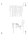
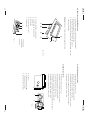
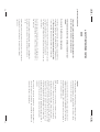
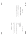
3.2.1 Terminal locations
Site in accordance with BS 5440-1:2000 and the document J.
Flue terminal positions for pitched roofs
fig. 2
9
UK/IRL
A
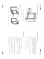
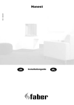
4. INSTRUCTIONS FOR INSTALLATION
A & B = Behind surround - Sleeve pipe through surround
C
C = Through wall - Pipe must be sleeved and sealed to fire
outer wall
cavity
inner wall
gas supply routes when fire is fitted in a deep surround
B
surround
marble
fig. 3
7. Where a gas pipe passes through a void, wall or cavity it must be
fully enclosed in a sleeve.
6. The gas connection is nut and olive suitable for 8 mm pipe.
5. The supply gas feed line should enter the appliance through one
of the openings in the appliance case. Openings are at the back
and right side.
4. The connection should be made in 8 mm copper or similar semi
flexible tube (max. 1 meter). Ensure that the gas pipe does not
interfere with the removal or replacement of the burner tray of
the controls.
3. A means of isolation must be provide in the supply to facilitate
servicing.
2. The complete installation including the meter must be tested for
soundness and purged as described in the above code.
1. Installation pipes should be in accordance with BS 6891. Pipe
work from the meter to the appliance must be of adequate size.
4.1 Gas connection
10
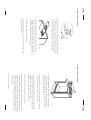
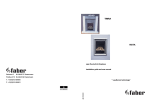
4.2 Preparing the appliance
4.2.1 Model Silva
fig. 4
UK/IRL
fig. 5
1. Open the door by pressing against the door at the bottom right
and remove the door (see fig. 4).
2. Remove the front by unscrewing the four screws.
3. Remove the glass by disassembling the securing frame (unfasten
the two screws on the bottom of the frame and remove the two
screws on top of the frame) (see fig. 5).
4. Take the box with the log set out of the combustion chamber.
11
UK/IRL
4.2 Preparing the appliance (continuing)
5. Remove the cable from the TTB (see fig. 6).
A
A
6. Remove the burner chamber out of the firebox.
A
A
B
1. Remove the front by loosening the screws A (see fig. 7).
4.2.2 Model Spectra
12
fig. 6
fig. 7
4.2 Preparing the appliance (continuing)
UK/IRL
2. Remove the glass by removing the glass clamps (B) for instance
with a screwdriver. Careful when removing the glass! (see fig. 7).
Wear gloves! Before placing the glass back, be sure that there are
no fingerprints on the glass, it is not possible to remove those
prints after you burn the appliance or a while (they will be
burnt in).
3. Take the box with the log set out of the combustion chamber.
4. Remove the cable from the TTB (see fig. 6).
5. Remove the burner chamber out of the firebox.
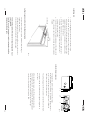
4.3 Fitting the firebox
1. Position the firebox in the fireplace opening.
2. If the appliance is placed on a combustible floor then a fibrelux
or similar heatproof board of 12 mm thickness should be placed
under it.
Any under floor vents or openings within the builders opening
should be sealed off.
3. The surface of the floor must be sufficiently flat to enable the
bottom of the front surround and door to be aligned horizontally.
4. The front face of the fireplace should be reasonably flat over the
area covered by the firebox to ensure good sealing.
5. Make the gas connection according to the instructions (also see
gas connection, chapter 4.1).
13
UK/IRL
fig. 8
9. Pull the clamping plate out. The flue collar plate makes contact
with the burner chamber.
8. Slide the burner chamber into the firebox.
7. Slide the clamping plate with the lip upward under the vent
connector. The flue connector and pipe or liner rests on the
clamping plate. Make sure that the lip of the clamping plate goes
in the slot on the front of the firebox (see fig. 9).
fig. 9
6. Secure the vent connector unit to the flue pipe or chimney liner.
The flue connector outer collar is for connection to a 125 mm
(5 inch) internal diameter pipe or liner. The inner collar is for
connection to a 100 mm internal pipe or liner (see fig. 8).
4.3 Fitting the firebox (continuing)
14
4.3 Fitting the firebox (continuing)
UK/IRL
fig. 10
10. Turn the clamping plate up-side down and slide the plate
between the guides so that its ends grip around the pipe
opening (see fig. 10). Make sure that the flue collar plate is
pressed onto the burner chamber.
11. If necessary, place the DC convection system (also consult the
instruction belonging to the DC construction set).
12. Spread the bag of embers (imitation ashes) provided with the
appliance over the burner. Do not use more than the quantity
supplied. The embers glow on low setting.
Note: there is no glow effect on the log burner.
13. Locate the log set (see placing log set, chapter 4.4).
14. Before placing the glass; check the glass sealing rope is in good
condition and makes an effective seal. Be sure that there are no
fingerprints on the glass. It is not possible to remove those prints
after you burn the appliance for a while (they are burnt in). Place
the glass in front of the appliance and fix the glass frame or use
the glass clamps.
15. Place the door and front.
15
UK/IRL
The log set consists of a rear log and five logs. Place the rear log
into the U section in the back of the combustion chamber.
The logs must be rest on the burner tray and the rear log.
Ensure that the pilot burner remains visible after installation of the
log set.
When not placing the log set correctly, the flames tend to burn to the
front against the window.
fig. 11 Silva log-set lay
Never place extra elements of any kind into the combustion chamber.
To guarantee good combustion, the log set may only be installed in
the way specified by Faber International. Any other arrangement can
lead to soot on logs or window. Do not use the fire with broken or
missing logs.
4.4 Placing the log set
4.4.1 Model Silva
16
4.4 Placing the log set (continuing)
4.4.2 Model Spectra (flatfibre burner)
A = large log
28 x 10 cm
B = medium log
24 x 9 cm
C = small log (wedge)
26 x 8 cm
UK/IRL
fig. 12 Spectra log-set lay
The log set consists of a rear log, which is permanently attached to
the combustion chamber, and four logs.
The logs must rest on the log holder and the rear log.
Ensure that the pilot burner remains visible after installation of the
log set.
When not placing the log set correctly, the flames tend to burn to the
front against the window.
17
UK/IRL
4.4 Placing the log set (continuing)
fig. 13
You are allowed to add different kind of embers on the burner tray to
create your own ash bed.
•L
location on the left side resting on the rear log.
•R
location on the right side resting on the rear log.
• 1 dimple first log left placed over the burner and resting on the
burner tray.
• 2 dimples placed in the middle over he burner and resting on the
burner tray.
• 3 dimples the right side log placed over the burner and resting on the
burner tray.
On the bottom of the logs is a identification:
4.4.3 Model Spectra (log burner)
To guarantee good combustion, the log set may only be installed in
the way specified by Faber International. Any other arangement can
lead to soot on logs or window. Do not use the fire with broken or
missing logs.
18
5.1 Remote control (if applicable)
5. REMOTE CONTROL
UK/IRL
The remote control is only meant to regulate the flames, it functions
only when the pilot burner is ignited. It is therefore not possible to
ignite the appliance with the remote control or to shut-off the pilotflame.
The radio-frequency remote control is intended for fireplaces installed
in a domestic setting in all EU countries, except Austria, Denmark,
Finland and Greece.
Features:
- Manual control will always remain possible.
- The remote control is a radio frequency type and has been
approved internationally.
- The remote control generates a unique safety code every time you
activate the transmitter, it's similar to those used in a car.
- The remote control is easy to install retrospectively.
5.2 Installation remote control
fig. 14
1. Connect the transformer to the receiver box. The transformer is
set to the correct voltage in the factory: 4.5 V.
2. Slide the receiver box into the holder.
19
UK/IRL
3. Connect the wires to the gas valve (see fig. 15).
fig. 15
4. Check that there are batteries in the transmitter. See "Replacing
batteries".
5. Set the on/off switch on the receiver to "on".
6. Check if you can hear a sound and the motor runs when you
push a button on the remote control.
5. The receiver now recognizes the remote control. The remote
control now functions.
4. Again push a button on the remote control. The lamp starts
flashing and will switch off eventually.
3. Push a button on the remote control. The control lamp on the
receiver should now go out.
2. The green control lamp will light up and stay on. Repeat this step
if not.
1. Push the "mod" button on the receiver and hold it for 3 seconds.
Setting the right transmission code
The receiver has to learn the code from the transmitter, which is
already set at the factory. However the code disappears if the
receiver is disconnected from the mains for a longer period.
20
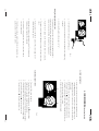
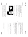
6.1. Check pilot ignition
A
6. COMMISSIONING
B
UK/IRL
(functional checks)
fig. 16
1. Push in and turn the control knob (A) anticlockwise to the
setting
(small flame). You will hear a tick meaning there is
ignition. Hold the knob in and wait for a few seconds while the
air is purged.
2. Bring the knob back in the start position and turn the knob
several times to the position. Check that the pilot has lit.
3. Continue to hold in the control knob for a further ten seconds to
ensure that the pilot flame is stable.
4. Release the knob. The pilot should remain alight.
6.2 Functional burner check
1. Turn knob (B) to max. clockwise.
2. Turn the knob (A) more anticlockwise to the position (large
flame). Now it is possible to light the main burner.
Turn knob B anticlockwise to max. The main burner should light.
Check the ignition of the main burner on low and high setting.
Turn knob B clockwise till {. The main burner is off.
Turn the knob A to {. The pilot should go out.
3.
4.
5.
6.
21
D C
B
B
6.5 Check reference pressure
A
fig. 18
UK/IRL
The pressure should be checked with the appliance alight and at
max. input.
After checking the pressure, turn off the appliance. Remove the
pressure gauge and close the sealing screw. Re-light the appliance.
Turn to max. input and test around the test point D for gas
soundness using a suitable leak detection fluid.
23
Fit a pressure gauge at the test point D to check the burner pressure.
The appliance is preset to give the correct heat input.
No further adjustment is necessary. Fit a pressure gauge at the test
pont C to check the input pressure. If the pressure is within the
limits then carry out the burner pressure.
A
UK/IRL
6.3 Spillage test
1.
2.
3.
4.
Carry out the lighting procedure and turn the fire to high.
Allow to warm up for 15 minutes and then using a smoke match
with holder set 100% inside the square tube on the top of the
appliance behind the door. The installation is satisfactory if the
smoke is drawn into the tube.
Repeat the test with doors and windows to the premises open
and closed, and with any extractor fans in the same room or
adjacent rooms running on high.
Check that any other open flued appliances and their flues in the
same or adjoining rooms functions correctly when this appliance
is alight.
smoke match
fig. 17
This monitoring system (TTB) must not be adjusted, bypassed or put
out of operation.
This TTB, or any of its parts, must only be exchanged using Faber
International authorised parts.
The pilot unit incorporates a system, which will shut off the gas
supply if the flue is faulty.
If the flue is faulty, the hot flue gasses will pass over and actuate a
heat sensitive switch, which will shut off the gas supply.
6.4 Flame Supervision & Blocked Flue Monitoring System
22
UK/IRL
24
7. HANDING OVER
8. SERVICING
UK/IRL
To ensure safety, efficient operation of the appliance, it is necessary
to carry out routine servicing at regular intervals.
(final check and customer briefing)
7.1
It is recommended, that the fire is inspected/serviced by a competent
person at least once a year.
Instruct the customer on the full operation of the appliance.
7.2.1 Advise the customer how to clean the appliance including the
glass.
Important
Turn off the gas supply before commencing any servicing. Always
test for gas soundness after refitting the appliance.
8.1 Routine annual servicing
7.2.2 Instruct the customer on the operation of the remote control,
including replacement of batteries and how to set the right
transmissions code.
7.2.3 Hand over these instructions including the user guide to the
consumer.
7.2.4 Recommend that the appliance should be serviced by a
competent person at least once a year.
1. Clean (if necessary):
- the pilot system;
- the burner;
- the combustion chamber;
- the glass.
2. Check the log lay and replace the embers (if applicable).
3. Do the functional test as described at 6.2.
4. Check the flue system and do a spillage test as described at 6.3.
Note
Never place extra elements of any kind into the combustion chamber.
To guarantee good combustion, the log set may only be installed in
the way specified by Faber International. Any other arrangement can
lead to soot on logs or window. Do not use the fire with broken or
missing logs.
25
Pilot assembly
Burner
Fixation plate
Injector
Gas control
Receiver
fig. 19
A
27
fig. 20
UK/IRL
8.1.3 Burner tray assembly log burner
1. Remove the front, glass, log set, grid and burner tray cover.
2. Break the gas supply at the control valve.
3. Unscrew the burner assembly and take them out of the
combustion chamber.
A.
B.
C.
D.
E.
F.
B
B
8.1.4 Pilot/thermocouple assembly
Remove the burner tray as described above.
Now you have access to all the pilot and thermocouple parts.
DD C
Governor
Adjusting screw pilot flame
Inlet pressure test point
Burner pressure test point
8.1.5 Gas control block
A.
B.
C.
D.
A
UK/IRL
8.1.1 Cleaning the glass
Depending on the intensity of use, you can get a deposit on the
glass. This can be removed with a special non abrasive ceramic glass
cleaner (ceramic cook-top cleaner) as follows:
1. Remove the door or front as described at 4.2.
2. Clean the glass. Handle the glass with clean hands, wear gloves if
possible.
3. To fit the glass, proceed in reverse order. Make sure that the log
set has been installed correctly before fixing the glass.
Attention:
Before placing the glass: check the glass sealing rope is in good
condition and makes an effective seal. Be sure that there are no
fingerprints on the glass. It is not possible to remove those prints
after you burn the appliance for a while (they are burnt in).
If the burner is visibly damaged, this can affect the distribution of
the flame, if so then replace the burner.
8.1.2 Cleaning the combustion chamber and burner
You can clean the combustion chamber with a vacuum cleaner
excluding the burner surface.
26
D
D
A
C
B
B
A
fig. 23
29
UK/IRL
8.1.7 Pilot/thermocouple assembly
- Remove the burner tray (see 8.1.3).
- Remove the lead from the pilot spark electrode.
- Break the gas pipe connection to the pilot.
- Unscrew thermocouple nut from the rear of the gas control.
- Unscrew pilot assembly from the burner tray (2 screws).
- Replace and re-assemble in reverse order.
Governor
Adjusting screw pilot flame
Inlet pressure test point
Burner pressure test point
DD C
8.1.8 Burner and injector
- Remove the burner tray (see 8.1.3).
- Unscrew the burner from the burner tray (4 screws).
- Break the gas connection at the burner inlet.
- Unscrew heat-shield from the burner tray.
- Unscrew elbow connection from the burner inlet.
- Unscrew the burner from the burner tray and remove the burner.
- Unscrew the injector from the burner inlet.
- Replace and re-assemble in reverse order.
A.
B.
C.
D.
B
C
A
UK/IRL
B
The pilot and flame sensing device
Injector (Spectra at burner inlet)
Burner tray
Gas control
Receiver remote control
Fixing bracket
F E
Attention! A sharp or heavy object can damage the burner.
A.
B.
C.
D.
E.
F.
A
A. Thermocouple
B. Spark electrode
C. Pilot hood
fig. 22
fig. 21 burner
8.1.6 Burner tray assembly flatfiber burner
1. Remove the front, glass and log holder (if applicable).
2. Break the gas supply at the control valve.
3. Remove the cable from the TTB (see fig. 6 and 8).
4. Unscrew the burner assembly (8 screws) and take them out of the
combustion chamber.
28
UK/IRL
A reading of CO in the room centre should give a rise of less than
9 ppm over ambient, peak reading.
A Ratio of CO/CO2 should be less than 0.01 within 30 minutes.
(100 ppm CO per 1% CO2).
8.1.9 Combustion test
A BS7967 combustion analysis check should be carried out using an
analyser to BS7927 positioned in the flue outlet, or draft diverter.
30
Silva
Company part
20816750
20816650
04508000
13382220
20817200
20772900
20604000
20603900
20900142
37003089
37003086
20900155
37002041
20900019
37006055
09000008
–
Spectra
Company part
A9264849
–
04506400
13382240
20900184
20773200
20604000
20603900
20900142
37003089
37003086
20900155
37002041
20900019
37006055
09000008
–
Spectra log burner
Company part
A9264849
–
04506400
13389170 / 13389160
20900183
20773700
20604000
20603900
20900142
37003089
37003086
20900145
37002041
20777300
37006055
UK/IRL
09000008
28103900
INDEX 1 LIST OF SPARE PARTS
Description
Surround silver
Door silver
Glass
Injector
Burner
Log set
Receiver
Remote control
Transformer
Gas control
Motor (remote control)
Pilot assembly
Thermo couple
Embers
TTB 110°
Black spray for
combustion chamber
Touch Latch assembly
31
UK/IRL
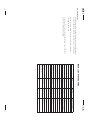
0.57
25
UK/IRL
I2H
Silva
BS11BS
G20
5.6
2
10
0.7
20
UK/IRL
I2H
Spectra
BS11BS
G20
6.6
2
8
0.7
20
17
0.24
29
UK/IRL
II2H3+
II2H3+
Spectra Log burner
BS11BS
G20
G30
7.5
7.7
2
2
INDEX 2 TECHNICAL DATA
10
2.4
2 x 1.70
1 x 1.60
1.8
kW
Gas rate (15° C / 1013 mbar) m3/h
Inlet pressure
mbar
2.2
1.6
Country
Category
Appliance
Model type
Reference gas
Input (nett)
Efficiency class
Reference burner pressure
mm
1.6
mbar
Injector size
mm
mm
m
230 VAC/50Hz/5VA
4.5 V
2 x LR03
Alkaline long life
8 mm nut and olive
GV36-C5AOEHC68M
100
3
SIT 145
Nr. 30
230 VAC/50Hz/5VA
4.5 V
2 x LR03
Alkaline long life
8 mm nut and olive
GV36-C5AOEHC68M
100
3
SIT 145
Nr. 30
230 VAC/50Hz/5VA
4.5 V
2 x LR03
Alkaline long life
8 mm nut and olive
GV36-C5AOEHC68M
100
3
SIT 160
Nr. 51
100
3
SIT 160
Nr.30
1.3
3 x 1.00
Reduced input restrictor
Pilot assembly
Type
Code
Flue
Flue size
Min. flue height
Gas control
Remote control
Transformer
Voltage transformer
Batteries remote control
Gas connection
Dimensions: see table 1
32
USER GUIDE
UK/IRL
33
UK/IRL
9. SAFETY INSTRUCTIONS FOR THE
USER
Switch off the receiver of the remote control if you don’t use the fire for
a long time. Do not let children use the remote control without
supervision.
Do not place curtains, clothing, laundry, furniture or other flammable
materials nearby the appliance. The required minimum distance is
100 cm.
Due to the newness of materials, they may give off a slight smell for a
period after initial lighting. This is normal, odours will disperse after a
few hours use.
The appliance has been designed for heating purposes. This means that
all surfaces, including the glass, can become very warm (over
100 degrees). An exception to this is the lower side of the door and the
control buttons.
The fire has a safety device which turns off the gas supply if there is a
build up from flue gasses in the combustion room or a temporary gas
cut-off. Wait at least 5 minutes before turning the appliance on again.
Contact a qualified installer when the appliance goes off regularly.
Do not use the fire with a broken or damaged glass.
These instructions should be read carefully and retained for future
reference.
If a gas leak is found or suspected, turn off the gas supply at the
meter and contact your installer or gas emergency service.
9.1 General safety instructions
34
UK/IRL
Important
A suitable Fireguard conforming to BS6539 and BS6778 should be
used with this appliance to protect children, the elderly or infirm.
Care should also be taken with pets.
In your own interest and that of safety, all gas appliances must be
installed by competent persons. Installation must be in accordance
with National Regulations. CORGI registered installers are required to
work to recognised standards.
Note:
Since the appliance is a source of heat, circulation of air occurs.
Therefore it is of importance that you do not use the appliance
shortly after a renovation of the home. Because of the natural
circulation of air, moist and volatile components from paint, building
materials, carpet etc. will be attracted. These components can settle
themselves down onto cold surfaces in the form of soot. As on all
heat producing appliances, soft furnishings such as blown vinyl
wallpaper placed too near to the appliance may become scorched or
discoloured. This should be born in mind when installing the
appliance.
We advise you to leave the pilot flame on. Leaving the pilot flame on
reduces the amount of condensation when starting the appliance and
increase the life time of the appliance.
35
UK/IRL
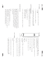
Knob A
10. CONTROLLING THE APPLIANCE
A
B
The { is the OFF position preventing any gas from passing through
the control valve to either the pilot burner or to the main burner. By
pressing the knob in it is possible to turn it anticlockwise. The first
function is to turn on the gas to the pilot- this occurs just before
reaching the |position (if the fire has not been lit for some time it
may be necessary to hold the knob in this position for some seconds
to clear the air from the pipe and allow gas to reach the pilot burner).
fig. 24 control unit
With control button A you can light the pilot. With the control
button B you can adjust the height of the flames (see fig. 24).
The control valve is behind the door or ash pan cover.
Open the door by pressing against the door at the bottom right
(Silva only).
We advise you to leave the pilot flame on. Leaving the pilot flame on
reduces the amount of condensation when starting the appliance and
increase the life time of the appliance.
If the main burner or pilot light are extinguished for any reason, do
not attempt to relight the pilot within 5 minutes. Contact a qualified
installer when the appliance goes off regularly.
10.1 Lighting the fire
36
Knob B
10.2 To light
UK/IRL
Once gas is available at the pilot, continued rotation anti-clockwise
will cause the piezo igniter to spark. This is accompanied by a click
at the valve and should result in the pilot burner igniting.
Once the pilot is lit, the control knob should be held pressed in for
10 seconds. In this time the pilot flame will have heated the flame
supervision thermocouple sufficiently to operate a hold-on magnet
within the valve.
Now turn the control knob A to the
position. This allows gas to
enter control knob B.
The { is the OFF position preventing gas entering the main burner if
the pilot is lit.
The knob should be turned slowly anticlockwise. This allows gas to
enter the burner and be ignited by the pilot flame. Once ignition has
taken place, the fire may be set to any level between min. and max.
by adjusting the control knob B.
1. Push in and turn the control knob (A) from { anticlockwise to
the setting
(small flame). You will hear an ignition click. Check
that the pilot is lit (if not repeat).
2. Continue to hold in the control knob for a further ten seconds to
ensure that the pilot flame is stable.
position.
3. Release the knob. The pilot should remain alight.
4. Turn the control knob A to the
5. Turn knob B slowly anticlockwise, the fire should then ignite.
6. Adjust flames to the required level.
37
UK/IRL
position.
10.3 To extinguish
1. For the main burner turn the control knob B clockwise to
position {.
2. To enable knob B turn knob A to the
3. To extinguish the pilot turn control knob A to position { ,
although it is in order lo leave the pilot permanently lit.
10.3.1 When the pilot extinguishes
Warning! When the pilot extinguishes, for whatever reason, you
should wait at least 5 minutes before trying to turn it on again.
Possible causes of pilot extinguish are:
- Operating error.
- Interference of the safety device.
- Failure in the pilot flame system.
Contact a qualified installer when the appliance goes off regularly.
Features:
- Manual control will always remain possible.
- The remote control is a radio frequency type and had been
approved internationally.
- The remote control generates a unique safety code every time you
activate the transmitter, it's similar to those used in a car.
- The remote control is easy to install retrospectively.
The remote control is only meant to regulate the flames from off till
max., it functions only when the pilot burner is ignited and knob A in
(big flame) position. It is therefore not possible to ignite the pilot
flame with the remote control or to extinguish the pilot flame. The
radio-frequency remote control is intended for fireplaces installed in
a domestic setting in all EU countries, except Austria, Denmark,
Finland and Greece.
10.4 Remote control version
38
10.4.1 To light
fig. 25
remote control
UK/IRL
1. Push in and turn the control knob (A) from { anticlockwise to
the setting (small flame). You will hear a ignition click. Check
that the pilot is lit (if not repeat).
2. Continue to hold in the control knob for a further ten seconds to
ensure that the pilot flame is stable.
position.
3. Release the knob. The pilot should remain alight.
4. Turn the control knob A to the
(low) to achieve the desired heating and
5. Set the on/off switch on the receiver to "on”.
low flame
high flame
6. Use
(high) and
flame effect.
7. You will hear a beep every time the receiver recognises a good
signal. (If not, so see 10.4.3, setting the right transmission code).
8. When the fire is not be used for a prolonged period, turn off the
pilot (see 10.4.2).
position.
10.4.2 To extinguish
1. Push
(low) till the burner goes out and you can hear the motor
clicking.
2. To enable the remote control turn knob A to the
3. To extinguish the pilot turn control knob A to position {,
although it is in order to leave the pilot permanently lit.
39
UK/IRL
5. It might be possible that you have to set the transmission code
after changing the batteries (see 10.4.3).
Note
Batteries are chemical waste and should be disposed in accordance
with local regulations.
41
4. Click the battery clip into the remote control and close the cover.
3. If necessary, remove the old batteries and place the new ones: 2 x
LR03 Alkaline long life 1.5 V. Pay attention to the + and - position.
2. Carefully remove the battery clip along the side. Pay attention not
to pull the wires.
Remote control
1. Remove the cover on the back of the remote control.
10.4.4 Changing the batteries (continuing)
+
UK/IRL
10.4.3 Setting the right transmission code
The receiver has to learn the code from the transmitter, which is
already done at the factory. However the code disappears if the
receiver is disconnected from the mains for a longer period.
1. Push the "mod" button on the receiver and hold it for 3 seconds.
2. The green control lamp will light up and stay on. Repeat this step
if not.
3. Push a button on the remote control. The control lamp on the
receiver should now go out.
+
changing batteries
fig. 26
AAA
4. Again push a button on the remote control. The lamp starts
flashing and will switch off eventually.
5. The receiver now recognizes the remote control. The remote
control now functions.
6. Check if you can hear a sound and the motor runs, when you
push a button on the remote control. (If not so please check the
batteries).
10.4.4 Changing the batteries
There is no risk of electric shock as the low voltage supply is similar
to that used in torches. Always turn off the appliance before changing
batteries.
40
AAA
UK/IRL
42
Important:
11. CLEANING AND SERVICE
INSTRUCTIONS
Turn off the fire and allow it to cool down before
commencing cleaning.
It is recommended that the fire is inspected/serviced, by a competent
person at least once a year.
To maintain the finish on the trim wipe with soft damp cloth only. Do
not use abrasive cleaners, polish or solvents as these can damage
the surface finish.
UK/IRL
12. DISPOSAL OF THE PACKAGING
AND THE APPLIANCE
The appliance packaging is recyclable. The packaging could include
the following materials:
cardboard;
CFC-free foam (soft);
wood;
plastic;
paper.
These materials should be disposed responsibly and in conformity
with government regulations.
Batteries are considered chemical waste. The batteries should be
disposed of responsibly and in conformity with government
regulations. Remove the batteries before disposing of the remote
control.
Information on how to responsibly dispose of discarded appliances
can be obtained from the local authorities.
43