1
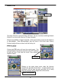
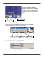
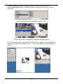
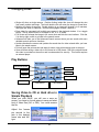
Full-Spectrum Unified Security Solutions
Product User Guide – Viewpoint Video System
Modular Digital Video System
DVR User Manual (Version 12)
10226 San Pedro Ave., Ste. 200
San Antonio, Texas 78216
Tel: 210-477-5400
Fax: 210-477-5401
Index
Touring Camera Set ............................ 31
Touring Schedule ................................ 32
Daily/Weekly Schedule........................ 33
General ...................................................3
Communication .....................................4
Throttle Bandwidth ...............................5
Modem .................................................6
Hardware Watchdog ............................7
Web Client ...........................................8
Alarm Over IP ......................................8
Logical Diagrams .................................. 34
Input Devices ....................................... 35
Physical Input Properties..................... 35
Video Lost Properties .......................... 36
Virtual Timer Properties....................... 36
Video Motion Properties ...................... 36
Alarm Over IP Properties..................... 37
Arm-Disarm Input Properties ............... 37
Physical Output Properties .................. 37
Camera Output Properties................... 37
Delay Properties .................................. 38
Event Record Properties ..................... 38
Spot Monitor Properties....................... 38
Notify Properties .................................. 39
Logical Operators ................................ 39
2 Point Link .......................................... 39
Remote Sites…………………………….. 9
Record on Demand ...............................10
Camera…………………………………… 11
Utilities ...................................................13
Software Watchdog..............................13
Backup and Restore ............................14
Database
Playback Option...................................14
Simple Playback ..................................14
Access Rights ....................................... 40
Adding Groups..................................... 40
User Levels.......................................... 42
Adding Users ....................................... 42
GUI Setup ...............................................15
Lock/Unlock Desktop ...........................16
Video Multi-View…………………………17
User’s Guide.......................................... 45
Logging In ............................................ 45
Finding Your Way Around ................... 46
Alarm I/Os............................................ 47
PTZ Control ......................................... 47
Camera Panel...................................... 48
Record On Demand............................. 48
Log Files .............................................. 49
Open an Activity Log File..................... 51
Pan Tilt Zoom (PTZ)……………………. 18
Adding Presets, Setting Auto...............20
Pan and Adjusting Speed
Alarm I/O ................................................21
Event Record .........................................22
Events Tab...........................................22
Creating an Event ................................22
Searching Video.................................... 52
Simple Playback .................................. 52
Changing Views................................... 53
Play Buttons......................................... 53
Saving Video to CD in ......................... 53
Simple Playback
Advanced Playback ............................. 54
Search by Date/Time........................... 54
Searching by Camera.......................... 55
Searching Video Motion ...................... 55
Detection and Smart Search
Working with Search Results............... 56
Controlling the Playback Screen ......... 57
Saving a Video File to Disk or CD ....... 58
Video Motion Detection ........................23
Motion Setting ......................................24
Recording Sets ....................................25
Recording Schedules...........................25
Continuous Recording .........................26
Notify ......................................................27
Voice Over IP .........................................29
Spot Monitor ..........................................30
Setting a Default Camera ....................30
2
General
The General dialog provides information for language, configuration resources, and
recording directories. It also contains the transmitter’s site information. The site
information must be entered to identify the transmitter, and recorded video. The Site ID
can be any number that does not start with a zero. The Site Name can be any friendly
name using letters and or numbers. The database path cannot be changed and is
shown for reference only.
The first time setup is run, or whenever the Wizard is used, the On Screen Keyboard
may appear. If the DVR has a keyboard attached, you can close the On Screen
Keyboard.
• Enter a number for the Site ID; it cannot start with a zero.
• Enter any combination of letters and numbers for the Site Name.
• Recording Directories: This specifies where the video files will be stored. Ensure
you are not storing video files on the C: drive or any drives with a red circle with
word low in it.
Auto Adding All Hard Drives:
This option is only used with
removable hard drives.
Add All Drives:
Click this button to quickly add
all the available drives on the
system. Ensure you remove the
C: drive from the selected list.
Add:
Allows selecting individual drives
to add to the list.
Edit:
This option opens the Pick a
Directory dialog box. Use this to
change an entry from one drive
to another.
Delete:
This will delete the selected
entry from the list. It does not delete the video files from the hard drive.
• Click Save
After entries and changes have been made, click Next to move to the next setup area.
3
Communication
Communication setup is the hub for all devices that will transfer data between the DVR
system and other devices. These devices can range from modems to cash registers.
What you see in the communication window will depend on which modules were
purchased with your system. The picture below shows devices that may or may not be
available on your system.
Note: The PTZ
module will be
covered in the
PTZ section.
If a needed module is not present in
the Communications window during
setup, click Add to enable the
particular feature.
Network
If you need to have Viewpoint log in to a Domain Server, See Utilities, Lock/Unlock
Desktop.
IP addresses are configured under the Windows Network setup. A fixed IP address is
preferred for the DVR Transmitter.
4
Throttle Bandwidth, Limit Incoming Connections and
Change Port Address
Throttle Bandwidth:
* If you are using Voice Over IP or the Web Client, you should throttle down the
bandwidth by at least 56k.
Shared bandwidth means that the DVR will open a TCP/IP connection that will open
wide enough for 1.5Mb of data. Regardless of the number of connections, the DVR will
not exceed the bandwidth selected from, or entered in this list. If a value you wish to
use does not appear in the dropdown list, simply type it in the box. For example, if you
are using Voice Over IP, and you have a 768k DSL connection, type 712 into the box.
Changing the Port Address:
• Double-click on Network in the Communication Window
• Click in the Port Address box
• Directly type in the Port Address
• Click OK
Limit Incoming Connections:
Type a number between 1 and 256 directly into the Incoming Connections box, or
select Maximum or No Connections.
5
Modem
Note: The modem is disabled for RAS support.
modem to modem communications.
Clear the disabled box to enable
To install a modem in the DVR:
• Install the modem in Windows.
information.
Refer to the modem manufacturer’s manual for
• In DVR, go to Communications and click Add.
• Select Modem in the list.
• Name the connection Modem.
• Under Device Type, select your modem from the list. (Any device that can be
classified as a modem in Windows will appear in the list, including Direct Connect
and Serial Cables.)
• Select the Com Port that the modem is using.
• The default Init String should work with most modems.
• The default Baud Rate of 56700 will work for 56k modems. Use 115200 or higher
for ISDN modems.
• Click the dropdown for Volume and select none if you do not want to hear the
modem.
• Select the Dialing Prefix of ATDT for regular modems. Use ATD for ISDN modems.
• Select the number of Answer Rings if desired.
• Click OK.
6
Hardware Watchdog
The hardware Watchdog is a device that is integrated with the video capture card and
listens for a signal from the system. Viewpoint will tell it that it’s active. If the Watchdog
does not get a response from Viewpoint, it will force a hard restart to bring the DVR
back up and recording. If the Watchdog senses mouse movement, or if Viewpoint is not
running, it will disable itself so as not to reset the system during other operations. The
Watchdog will also clear any error message or dialog box while the DVR is running.
You may have to disable it or close Viewpoint while performing some tasks in Windows.
Note: The default setting for Watchdog is OFF. This will prevent the Watchdog from
resetting the system or clearing dialog boxes during initial setup. It is safe to enable it
now. To add the hardware watchdog or edit it’s properties:
• Click on Watchdog.
• Click Edit.
• Click on the Disabled checkbox to remove the check and enable this feature.
7
Web Client
To enable the Web Client:
• Click the Add button in the Communications Setup window.
• Click on the Web Client in the Connection Device list.
• Enter a Connection Name.
• Uncheck the Disable box to enable the Web Client.
• Click OK
Note: The web client Java applet works through port 80, however the video is
transmitted over port 7128 by default. If a firewall is between the Web Client and the
Transmitter, then both ports must be open.
Alarm Over IP
Alarm over IP provides a simple and effective means for developers to build an
application that can send data across a network and trigger an alarm state to the
Transmitter. The format for developers may be obtained by contacting MDI’s technical
support.
8
Remote Sites
The Remote Sites Database is a list of computers running Viewpoint Receiver Software
that can be accessed. This is primarily used for notify.
When setting up the DVR and Receiver, it is helpful to think of the Remote Site as the
location you are calling to. The Site ID and Site Name can be found in the Receiver’s
General Setup, if you need to find it to configure notify.
The Site ID, Site Name, Phone Number or IP Address are the only required fields that
must be filled for the Notify Module to work.
To configure Remote Sites for Notify:
• Click Add.
• Enter a Site ID. (numerical and cannot start with a zero)
• Enter a Site Name. (alpha numeric)
• Enter a Phone Number. If using a modem, you may need to precede the phone
number with a nine and a comma (9,) to access an outside line.
• Enter an IP Address.
• Click OK
Each site you enter will appear in the Site ID list. If you need to edit or delete entries,
you must first select it or you will delete or edit the first entry.
9
Record on Demand
Record on demand can be initiated by remote users or by operators at the local site.
Record on Demand will record at the highest frame rate possible, but will not stop other
recording that is going on in the system. If you are viewing a single camera when
Record on Demand is activated, it will record that camera until it is manually stopped. If
you are viewing four cameras at the time it is activated you will record all four cameras
until it is manually stopped.
Note: Because of the frame rate and the need to manually stop this type of recording, it
is possible to use up a lot of disk space without realizing it.
Frame Rate
Select the number of frames per second you wish to record at.
10
Camera
Camera setup allows the selection of camera attributes for how the video will be
recorded. Once selected, these settings apply to all cameras. Blue icons are disabled
cameras and yellow icons are enabled cameras. Audio selections will also be setup
here in the cameras setup next to each camera name.
Video Standard
Select from NTSC, PAL or SECAM.
Video Format
OVERLAY DIRECT is default for on-board VGA or low end VGA
OVERLAY INDIRECT might be use to improve image for High-end VGA
Recording Size
Select size: 360x240 / 360x288 (NTSC/PAL) or 720x480 / 720x576 (NTSC/PAL).
(720x480 / 720x576 NTSC/PAL wills effectively double the required disk space
needed for storage of video and/or also drop the frame rates on the board)
Compression Format
XPEG is a proprietary version of the MPEG4 compression format and uses key frames
for capture.
11
Analog Ports
Tells you have many Analog ports are available.
Virtural Ports
Tells you have many IP ports are available if licensed.
Quality
Select between 1 and 15. (The higher the number the larger the video storage
space required)
Total Boards
Displays the number of capture cards installed in the system.
Cameras
Cameras can be enabled or disabled. (It is advisable to disable any cameras that
don’t have a physical camera attached to it)
Audio Channels
Audio can be associated to each camera. The drop down allows selecting audio to be
associated with the camera beside it.
Brightness
Adjusting the sliders will allow you to obtain the best image possible from your camera.
Contrast,
Adjusting the sliders will allow you to obtain the best image possible from your camera.
Hue,
Adjusting the sliders will allow you to obtain the best image possible from your camera.
Saturation
Adjusting the sliders will allow you to obtain the best image possible from your camera.
Note: You could change the camera name by highlighting the camera you want and
click on the change name button. Type in the name you want and press enter key on
your keyboard or you can double-click on it in the list or select it and. (Only used
alphabet letters A-Z and numbers 0-9 only, no special symbol)
12
Utilities
Utilities allow setting your Watchdog, Backup and Restore of the database, the playback
option, GUI Setup and Lock/Unlock Desktop
Software Watchdog
The Software Watchdog will reset the system to refresh system memory and verify that
the file system is in good condition as scheduled. (Optional)
Weekly: will allow you to choose any day of the
week and at any time you desire to reset your
DVR
Daily: will automatic set all the days of the week
to reset your DVR.
13
Backup and Restore Database
The database referred to here is the machine’s configuration settings. It contains all the
cameras, users, recording settings, etc. This is useful should you need to restore your
configuration.
Backup
• Click Backup.
• Select a folder and filename from the dialog box.
• When complete click Exit.
Restore
• Click Restore.
• Select the file to be restored from the dialog.
• When complete click Exit.
Playback Option
Viewpoint offers two ways of finding the video for playback. (Simple and Advanced)
Simple playback uses a line based time bar to allow selecting video for playback. While
limited in its functionality, it can be easier to use than advanced playback. Advanced
Playback allows for more detailed searching criteria and additional options for searching
and replaying video.
Simple Playback
When checked the playback button in the main interface will
open the simple playback screen when you search for video.
If using simple playback, select the default recorded format
you wish to view. Motion Detection, Continuous or Events
are available to choose from. If unchecked, the advanced
search will open.
14
GUI Setup
The icons available on the main GUI can be added or removed to suit your needs.
Simply dragging an icon onto or off of the GUI will add or remove it.
To align icons on the GUI, click the dropdown arrow on the box and select the
appropriate alignment for you. Click the X at the top right of the screen to exit the GUI
setup screen.
You could also change the picture icon to word icon: right click on the picture you want
to change to word icon and choose text.
15
Lock/Unlock Desktop
The desktop can be locked to keep users from accessing anything other than the DVR.
Applications other than Viewpoint can run at startup. Click the Add button and browse
to the programs folder and select the executable file for the program.
To enable this feature check the Lock Desktop checkbox.
If the DVR is on a network, and is made part of the domain,
• Select Log on automatically at system startup.
• Enter the User’s Name and Password and the Domain name.
• Click Apply.
Note: After configuring Lock/Unlock Desktop the system will reboot to apply setting
changed after exiting setup.
16
Video Multi-View
This setup allows you to configure the cameras you want to see in each view.
By clicking on the dropdown button in the top right corner of each camera box, you can
select which camera you want in that area.
Clicking on the checkered boxes at the bottom will change between views. The last
view you select before closing this setup window will be the default view when the
system starts.
17
Pan Tilt Zoom (PTZ)
Numerous popular PTZ camera protocols have been included in the DVR software.
Some features displayed on the screens may not be available with all cameras. Check
your manufacturer’s directions for details.
Begin by attaching the PTZ camera(s) to the system per the camera manufacturer’s
instructions. Keep the following in mind when hooking up the cameras:
• Address the camera as described by the manufacturer.
• If at all possible, plug the BNC connector into the camera that matches the
address.
• Make sure you are using the correct protocol for your dome. (only one protocol can
be utilized)
The camera’s address is how Viewpoint knows which camera to send instructions to.
The data connection will require a RS232 to RS485 adapter connected to the Com port.
Once you have made the physical connections:
• Double-click on the Communications icon in Setup. Either selects the PTZ entry
or clicks Add and adds it to the list.
• Enter a Name for the connection
• Select the appropriate Com Port
• Set the appropriate baud rate, parity, data bits and stop bits per your camera
manufacturer’s instruction.
• Click OK and Close the Communications window.
18
Setup PTZ in PTZ setup icon
• Double-click the PTZ icon in Setup and select the PTZ camera from the list.
• Check the PTZ Enable box at the bottom right
• Select the PTZ Type by using the dropdown and picking from the list.
• If required, click Change PTZ ID and change the address used.
• Click to the right or left of the joystick and check for camera movement.
• It should now move right or left at your commands.
• Click OK
19
Adding Presets, Setting Auto Pan, and Adjusting Speed
To add a preset:
• Position the camera where you want it to move to.
• Click Add
• Name the preset and press Enter on the keyboard
• Click OK
To set up Auto Pan:
• Position the dome to the left and click Set Left.
• Position the dome to the right and click Set Right.
• Click Auto to start.
Note: Not all PTZ cameras support Auto Pan and now all PTZ setup the auto pan the
same way (please refer to ptz manuals)
To adjust the Pan and Tilt Speed:
• Check the box next to Pan Speed Setting
• Adjust the settings for Low Medium and High
• Click the Save button
• Uncheck the Pan Speed Setting box
• Use the same procedure to set Tilt Speed
20
Alarm I/O
The I/O setup display panel is divided into two sections: Inputs and Outputs.
The tabs across the top allow moving between groups of I/O if your machine
is so configured.
***NOTE (BEFORE TESTING I/O, PLEASE GO TO CAMERAS SETUP FIRST) ***
Inputs
Inputs are yellow by default meaning they are enabled. You can left click on each one
to disable it. It will be blue when disabled. When testing an active input it will turn red.
Outputs
Outputs are yellow by default meaning they are enabled. If an output is locked it will be
blue. It cannot be manually triggered in the Main GUI. It can however be tripped by an
input that has been assigned to it in the Logical Diagram. In that case the output will
remain active until the timer on the output has elapsed. This prevents anyone from
turning off the output either from a Receiver or Transmitter.
Activated outputs are green and can be triggered from the Main GUI.
Clicking the Testing toggle button will put the I/O interface in testing mode. When an
input is tripped successfully, the button indicator will turn red. When an output is
successfully triggered it will turn green.
For more detailed information about I/O, see Logical Diagram.
21
Event Record
Event Record is used when an activity or Input triggers the recording of an event.
Events can be searched separately from other types of recordings.
Events Tab
• To add an event click Add
• To modify an existing event click Edit
• To remove an existing event click Delete
• To enable or disable an existing event click the appropriate entry
Creating an Event
• Click Add.
• Select the event duration from the drop
downs.
• Select the required frame rate.
• Choose the camera to associate this event
with.
• If a preset position is to be used, select it.
• If Pre-Event recording is required set the
duration and check the Active box.
• If Post-Event recording is required set the
duration and check the Active box.
• If you want to overwrite older events, check
the Overwrite box. If this box is not checked
the event recordings will remain indefinitely.
• Click OK
22
Video Motion Detection Recording
Video motion detection allows recording only when movement is detected in the
configured camera(s). This will provide high quality recordings and also save disk
space by only saving video when triggered.
Camera Selection
• Select cameras from the Available Camera window.
• Click the right arrow to move the camera to the Selected Cameras window.
• Click on the Motion Setting tab to move to the next step.
23
Motion Setting
• Select the camera to configure from the right window.
• You could click the area in the picture where you want to detect motion or re-click
on the selected area to erase the selected detect motion.
• Click the Mask All button to mark all the available areas.
• Click the UnMask All button to remove all selected areas.
• The quadrants will flash red when movement is detected in the image.
• Select the Object Size based on the approximate size of objects you want to
detect within the image.
• Select the Number of differences required to trigger motion. The lower the
number the more sensitive the detection will be.
• Snapshot button is for creating a picture for smart search, recommended pressing
after each camera is masked.
• Click on the Recording Sets tab to continue to the next step.
24
Recording Sets
• To add a Recording Set, click the Add button
• Select the cameras from the Available Cameras window and use the right arrow
to move them to the Selected Cameras window.
• Set the recording duration using the boxes above the Selected Cameras list. This
determines how long after motion is triggered that the recording will continue. If
set for 30 seconds, motion is triggered and after 20 seconds another motion is
detected, the time will start over for the 30 seconds. Each camera can be set
independently.
• Set the required Frame rate for
each camera or you could click
the first camera and hold down
the shift key and click the last
cameras and set the frame rate
(will applies to all cameras
selected) Each camera can be
set independently
• If Pre-Event recording is required,
set the duration and check the
Active box.
• Select the camera associated
with this Pre recording.
• If
Post-Event
recording
is
required, set the duration and
check the Active box.
• Select the camera associated
with this Post recording.
• Click Save.
Recording Schedules
• Select Daily, Custom or Weekly under Schedule.
• Adjust the times for the set.
• Click OK
To add a recording
schedule: Click Add.
25
Continuous Recording
Continuous recording allows cameras to record continuously at lower frame rates.
Add a Recording Set
• Click the Add button.
• Select the cameras from the Available Cameras window and use the right arrow
• To move them to the Selected Cameras window.
• If Audio recording is required, enable it for the appropriate camera(s)
• Adjust the frame rate for each camera.
• Click Save.
• Click on the Recording Schedules tab to move to the next step.
Recording Schedules
• Select Daily, Custom or
Weekly under Schedule.
• Adjust the times for the set.
• Click OK
To add a recording
schedule: Click Add.
26
Notify
Notify can be triggered by any physical input that has been enabled in the Input/Output
Module. It will start an event recording and send either a picture or message to the
client configured for notification.
In order for notify to work, you must have the client being notified entered into the
Remote Sites in Setup. You must also configure a relationship in Logical Diagram in
Setup.
Adding Notify Entries:
• Click Add
• Enter a Notify Name.
• Select a Notified Priority from the dropdown list.
• Select an Option for connection.
27
Connection Option
o Broadcast Connection – Broadcasts the notification across the network and
any authorized client will receive the notification. This is not the ideal way of
configuring.
o Connect only to one site – If you have multiple clients and want only one to
receive the notification, this is your best choice.
o Sequence Connection – will notify each client in turn.
• If at some point you want to stop notifications from going to a specific client, click
the Disabled block.
• Select the number of frames of video to send to the client.
• Use the Right arrow to move the entry over to the right window.
• When the entry moves over the following menu appears.
Configure Properties:
• Redial – how many times the notification will try to connect to the client.
• Set the time between redials.
• Kiss Off – This will determine how long the Transmitter will stay connected to the
receiver. If unchecked the two will remain connected as long as possible.
• Username – Select the user to be notified if User Profiles are being used.
28
Voice Over IP
Voice over IP is used to remotely listen in, announce, or have a two way conversation
between the transmitter and receiver. It is possible to configure this module to place a
microphone and speaker at a camera location, but will require additional equipment. All
you have to do is have the Enable Voice Over IP check.
To enable Voice over IP
check the box.
29
Spot Monitor
Spot monitors can be used to display a single camera on each monitor and to rotate
through specific cameras on different schedules.
Setting a Default Camera
If you only want to see a particular camera on a spot monitor, this step is all that is
required.
• Click on Edit and select a spot monitor and rename it if required.
• Choose a camera from the dropdown list.
• Click Save.
If you want to assign multiple cameras to run through a programmed routine on the spot
monitor:
• Click on the Touring Camera Set to move to the next step.
30
Touring Camera Set
• Click Add.
• Select the cameras to move into the Selected Cameras window. Cameras can be
added more than once.
• Adjust the Cycle Time for each camera.
• One set will control all three spot monitor output.
• Click Save.
• Click Touring Schedule tab to move to the next step.
31
Touring Schedule
• Click Add at the bottom left.
• Rename the Schedule if required.
• Click the Add button under the Set Name.
• Click in the box for the spot monitor you want to activate.
• Change the time values to meet your needs.
• Click Save.
• Repeat these steps for additional spot monitors if required.
• Click on Daily/Weekly Schedule to move to the next step.
32
Daily/Weekly Schedule
• Select Daily or Weekly. Default turns off scheduling and sends camera one to
spot monitor one. (select Daily for touring
• Select the Schedule Name you want to schedule.
• If Weekly is selected, choose the days to run the schedule.
• Click Save
• Click Close
33
Logical Diagrams
Logical diagrams work by cause and effect to provide automation for I/O, Notify, and
Events.
Input devices are bound to a relationship that relays the signal to one or more output
devices.
Inputs can be physical dry contact triggers, Video Motion Detection, Video Loss
Detection, Alarm Over IP, or a Virtual Timer.
Outputs can be Physical Outputs, Lights, Sirens, Event recording, Notify or a Camera.
To use multiple Inputs, you must first connect to a Logical Operator, then to a
Relationship.
Multiple Outputs connect directly from the Relationship.
The Logical Diagram Toolbar
Create New
Relationship
Input
Devices
2 Point
Links
Output Devices
Edit Relationship
Name
Logical
Delete
Operators
Relationship
Always create relationships in the following order:
• Relationship
• Input
• Output
• Logical Operators
• Links
The design grid has relationship 1 on the screen by default. To change the name either
right click on the name or click on the Edit Relationship Name.
34
Input Devices
Physical inputs, Virtual Timers, Alarm Over IP and Video Motion Detection qualify as
Input Devices. You can place up to 68 Physical Inputs on the Design Grid.
Physical Input Properties
The physical Input properties page includes a
Disabled checkbox to disable the device. This
allows you to deactivate the device through
software rather than physically disconnecting it.
The Edge Trigger is for devices that will complete
or open a circuit. These are devices such as
buttons or door/window contacts.
A Level Trigger is for devices such as the Spot Monitor. If the input is a toggle switch
that the operator would flip for an indefinite period, select Level Trigger. If it is a push
button that will release when the operators stops pushing down, use Edge Trigger.
You can set a delay on these triggers to allow for something else to occur before it
triggers.
35
Video Lost Properties
• Select Disable if required later.
• Select All or any cameras.
• Click OK
Virtual Timer Properties
• Select Disabled if required later
• Timer can be set to repeat at set intervals
• Selecting Schedule will open additional
options to configure.
• Virtual timer is not limited to Event
Recording. It can be configured to turn on a
light at 7 pm and turn off 12 hours later.
• Select the appropriate days of the week as
needed.
Video Motion Properties
• Select Disabled if required.
• Select the required camera.
• Click OK
36
Alarm Over IP Properties
• Select Disabled if required
• Select the camera associated with the alarm.
Arm-Disarm Input Properties
This function works with a keypad to
Activate - deactivate a device.
• Select Disabled if required
• Select the Keypad Input
• Set the Delay if required
• Select the Zone if required
• Click OK
Physical Output Properties
Physical outputs are latched and set on by default.
Set On can be used to disable the output without
disconnecting it or removing it from the Logical
Diagram.
• Remove the check from latch to set the timer
for how long an output will stay on before
automatically turning off.
• With latch checked, the output will remain
active until it is physically turned off in the
Transmitter window.
• If using Notify with an output, do not lock it in I/O setup. That way a remote user
can turn it off from the Receiver.
Camera Output Properties
• Select the camera to display on the screen
37
Delay Properties
If you need to delay an output device, such as
closing a gate or lock a door, place a delay
between the relationship and the output device.
• Select the time for the delay.
• Name the delay if required.
Event Record Properties
• Click Disabled if required.
• Click Select Event and another window will
open for selection.
• Select the Event from the event list.
• Click OK
Spot Monitor Properties
• Click Disabled if required.
• Select the appropriate Spot monitor.
• Select the camera to display.
• Click OK.
38
Notify Properties
• Click Disabled if required.
• Select video from an event.
• Select video from a camera.
• Select video from a preset.
• Select to transmit a message.
• Select a camera to display.
• Click OK.
If selecting a message, this dialog will open to allow
creating the message.
Logical Operators
Logical operators allow flexibility in working with the inputs and outputs.
• Select And to require multiple inputs be present to activate an output.
• Select Or to require that one or the other be present to activate an
output.
Logical operators go between the Input and the Relationship
2 Point Link
2 point links connect the relationship together.
• Click on the 2 point link and drag it to the Input device
• Drag it to the relationship
• Click on the 2 point link and drag it to the relationship
• Drag it to the Output device
39
Access Rights
The access rights module prevents users from accessing setup, cameras, playback,
etc. Users are assigned to groups that have specific access rights to any part of the
program or setup. Users can be limited by hours or days.
Individual users can connect only one at a time. That is, if user Joe is connected
another user cannot use his user profile from another receiver station to connect to the
transmitter Joe is connected to.
Access Rights includes a default user named Admin with the password of mdi for initial
system access. The Admin account cannot be deleted, but it is highly recommended
that the password be changed right away and kept in a safe place. Installing dealers
should create an admin account in case the customer loses their password.
It is advisable to setup users in the following order:
• Create Groups (click the Access Rights icon first)
• Assign rights to groups
• Create users
• Assign users to the groups.
Adding Groups
• Double click the Access Rights icon
40
• Click Add Group.
• Enter the name for the group.
• Press Enter.
• Select the group
• Move through all Access Rights tabs selecting privileges for that group.
A check mark allows that privilege, uncheck denies the privilege. Some privileges have
dependencies and you will be prompted when selecting a feature that relies on another
to work. Each tab requires saving when finished before moving to the next tab.
Most privileges are self explanatory. One that is not is the Command Time Out under
PTZs. When checked and set to the required seconds the Command Time Out
prevents users from walking on each other when moving PTZ cameras. If Joe moves a
PTZ camera with the settings below, Jane would have to wait 10 seconds after Joe
finishes before she can move the PTZ.
41
User Levels
User levels determine how much control and priority a particular group of users has. In
the example below, Admin is user level 1. Supervisors are set to 2 and Guards are set
to 3. This affects who has a higher priority when using PTZs and Notifications.
Adding Users
You must create a user account for each user accessing the system. Double click on
users’ icon.
To create a new user:
Click Add
42
• The account can be disabled by un-checking the Enabled box.
• Enter the user’s information and assign a username and password.
• If you require an Expiration Date another window will open
• Select the expiration date from the calendar
• If you require a Time Restriction another window will open.
43
• If you required a Time Restriction another window will
open
• Select the From and To times from the dropdowns.
• Select the days of the week.
• Click Save.
After all information is entered for this
user click Save and click Close.
• Click Assign to assign this user to
a group.
• Select the group(s) from the left
and use the right arrow to assign
them.
• Click Save and then Close.
44
User’s Guide
Logging In
The main screen can be closed to hide live video and require users log in with their user
profile.
Click here
to log out
When logged out your screen will appear as below.
45
• To log in, click the Log In button. A login dialog box will appear.
• If required, change to your user name and enter your password.
• Click OK.
Finding Your Way Around
The right side of the screen is your main control area. The buttons available allow you
to change between various functions easily and graphically.
Remember that you can change the way the GUI looks in setup and that some functions
may not be available depending on what modules were purchased.
46
Alarm I/Os
Alarm I/Os
The alarm I/O button opens the Alarm I/O Panel. The top row allows switching between
Outputs if you have more than one I/O board installed.
Outputs are available to trigger if required. Active Inputs show up and can be clicked on
to acknowledge. Once acknowledged, they will move to the Active Input History.
Double clicking will remove them from the History list.
PTZ Control
Clicking the PTZ button will open the control panel. The
panel provides all movement controls for the PTZ cameras
as well as Zoom, Focus and Iris control if the camera is
capable of each.
PTZ control
Clicking on the green down arrow under the direction
controls will open the Preset Panel. If preset positions are
configured, the will show up here and allow you to easily
move the cameras using a single click of the mouse.
Preset Touring Button
47
Clicking on the Preset Touring button will open
the Preset Touring Panel. If presets are available,
you can select and schedule them to run through
a cycle that you can establish in this screen.
Note: Once a touring cycle is configured the entire
machine must be restarted to activate it.
Add, Start & Stop
PTZ control can also be done using the mouse from within the image window. Just left
and right of center in the image you will see the mouse cursor turn into a minus or plus
sign inside a circle. This will zoom in or out. Around the edges of the image you will
see the cursor turn to an arrow pointing in the appropriate direction for movement.
Simply move the mouse to the point that provides the correct arrow and hold down and
release the left mouse button. This will move the camera in the direction of the arrow.
The camera will move as long as the mouse button is held down. Playing with how the
mouse moves the camera, you will soon master the different positions.
Camera Panel
Camera Panel
The Camera Panel button will open the camera panel and
allow you to select which camera is displayed in any viewing
area.
Record on Demand
Record on Demand
The Record on Demand Button will open the Record on
Demand Control Panel. Adjust the frames per second if
required, click record to begin and click Stop to end
recording.
48
Log Files
The View Log File Button opens two
selections. Notify and Activity Log buttons.
The Notify Log Button will open a window
that will cover the lower blue area of the
screen.
View Log Files
Notify & Activity
Logs
The Log File Panel provides a listing of events that were sent to Receivers.
All notifications sent can be viewed at the Transmitter.
Delete
Open File
Save to File
Select a log file by clicking on the Open File button
Choose the appropriate log file and click OK
49
Print Preview
To save a single notify event to a log file, select the event in the notify files list
Click the Save to File button. Choose the location to save the file and give it a name.
Click Save.
Play, Forward and Back are available for video control
The play image can be enlarged by clicking the magnifying glass.
The Print Preview button will open the window below. Images can be enhanced to
some degree using the available controls. You can also add text to the image to be
printed.
50
Open an Activity Log File
Click the View
Log File Button
Click the Activity
Log Button
This opens a separate window in which to view and search the Activity Log File.
Search by Time/Date, All Users or individual users.
Click the print button to generate a report of users’ activity if required.
51
Searching Video
Search Button
Depending on your Setup configuration this will either open the Simple Playback or
Advanced Playback.
Simple Playback
Current Date & Time
Change the viewing arrangement
Video Playback Controls
Date & Time of Video
Camera
Selector
Slider can move
to different times
The Seconds/Minutes
button will change
the state of the
Bars show Minutes and
Seconds of recorded video
• Black bars are Continuous Record Files
• Green bars are Event Record Files
• Blue bars are Motion Detection Files
• Bars with red line in it have audio
52
Changing Views
• Single will show a single camera. Double clicking inside this view will change the size
from small, medium and large. The fourth double click will return the image to normal size.
• Multiple will display 4 cameras. Double clicking in an image will change it to 9 cameras,
and again will show 16 cameras. Double clicking again will take it back to 4.
• Pano (short for panoramic) will multiply one camera in the playback window. It is a toggle
button. That is, when clicked, it will switch to a 4, 9, or 16 views.
• Full Screen will enlarge the image to full screen size and hide the user interface. Click the
X in the top right corner to go back to the search screen.
• Advanced will take you to the Advanced Search screen where you can search with more
detailed controls and more functions.
• Update refreshes the screen and updates the search bar for video missed while you have
been in the search screen.
• Print will open the print screen and allow for some video enhancement prior to the print.
• Save will allow saving a video clip in AVI format or in DBI format. DBI is the original format
the video is recorded on the server and is watermarked for security. This format requires
an external player.
Play Buttons
Adjust play speed
Stop
Reverse
Play
Pause
Go to Start
Go to End
Fast Rewind
Fast Forward
Saving Video to CD or Hard drive in
Simple Playback
When you click SAVE, you will see a save as
screen; you have to choose where to save and what
kind of video files (AVI or DBI). You could rename
the file.
Adjust the frames
per second to the
rate to the desired
frame rate and AVI
type.
53
Advanced Playback
The advanced search window provides numerous ways of searching for recorded video.
All selection boxes can be checked together, combining search methods to narrow your
search results.
• Searching Path allows searching for video files that has been saved to the local
hard drive or CD.
• By Date/Time provides searching a specific time frame.
• By Camera produces results from particular cameras.
• Record on Demand returns results for manually recorded files using the Record on
Demand button on the main GUI.
• Continuous Recording allows searching through recordings of this type.
• Video Motion Detection returns results recorded from motion triggers.
• Event searches through event recordings.
• If additional modules are purchased, you will see the options for searching in this
screen as well.
Search by Date/Time
You can directly enter the date and time into the boxes or click on the Calendars button
to open and select a date/time.
54
Searching by Camera
Clicking on the Camera button will open a Camera selection dialog box. Combined with
Date/Time, this can be very useful in narrowing down incidents.
Searching Video Motion Detection and Smart Search
When Smart Search is checked an additional area opens allowing selection of specific
areas to search for motion. This can be very useful in determining when an object was
moved and who moved it.
55
Working with Search Results
When search results are returned, you will see this dialog box
on the right side of the screen. Depending on your search
criteria, your results may look slightly different, but the same
operations apply here.
• Click on the plus sign beside of the recording type to
view available cameras.
• Click on the camera to view the recorded files below.
• Select a file by clicking on it. Left clicking on the first file
and then right clicking on three subsequent files will
allow selecting up to four video files to view at one time.
• Once selected, drag and drop the file(s) to the left of the
dialog box.
• Each file will open and is available for viewing.
• All open files can be played simultaneously by clicking
on the play button at the bottom right of the Playback
Dialog Box.
• Click the Pause button to stop play.
• Click the Stop button to close all the open files.
• This icon indicates a recording with Pre and Post recording available.
56
Controlling the Playback Screen
From left to right, the control buttons are:
• Go to the first frame
• Jumps backwards
• Jumps forward
• Go to the last frame
• Play/Pause
• Jump to the previous clip
• Jump to the next clip
• Copy video to file or CD as AVI or BFI (original format)
• Disregard this button
• Print a still image
• View in full screen
• View Pre-Event video
• View Post-Event video
• View transaction data from cash register or ATM machine (Software modules
required)
• View information about the video file. Frame count, record start and stop date and
time, etc.
57
• Playback controls. Adjust speed, repeat, audio, frame by frame.
Slider can move
between frames
Right clicking on
the slider will allow
entering frame #
to go to
Drag these sliders to
restrict the playback
to a range of frames
Saving a Video File to Disk or CD
Click the Copy to Disk button on the playback window. The Download Options window
will open.
• Select between Original Format or AVI Format.
• There are two formats for AVI: Default DVR codec (needed ffshow installed to
playback) or Microsoft MPEG-4 (window media standard)
• Click the Browse to choose when to save the video file to. You could copy both AVI
and Original at the same time (just have both checked)
• Rename the file name if desired.
• Use the sliders to adjust how much of the file you wish to save if needed.
• Click the ok button to start saving
• Click close after the file is completed
58
Recommended System Requirements
(16-cameras systems) Petamotion
Intel Core 2 Duo CPU 2.4 or higher
2GB RAM or more
Motherboard with Intel Chipsets
1024x768 SVGA Screen Resolutions
VGA if used w/ 512GB of memory
Windows: XP (To install you must be logged with administrator rights)
(32-cameras systems) Especially Petamotion 480 & 240
Intel Core 2 Quad CPU 2.4 or higher
2GB RAM or more
***NOTES***
- DVR will reboot itself if system continuously ran 24 straight days without restarting.
- Naming camera: only used alphabet letters A-Z and numbers 0-9 only, no special symbol
- After the first initial setup for new version, the DVR will reboot
- Java version for Web Client: Java version 6 update 1 is recommended for fast log-in
- I/O Testing: Have to go to cameras setup first, before testing I/O.
- Recommend putting the installation files in C: Drive before installing the software, so if
software files get corrupted or missing, it could automatically go to install files when it first
install to reinstall the missing or corrupted files.
- If hard drive is bad or remove from system without removing from record partition setup, DVR
software will reinstall itself from installation files where it first installs from. Bad hard drive
could caused the system to stop recording
Petamotion 120 board:
Real-Time display: 480/400 (NTSC/PAL)
Board Frame Rates: CIF 120/100 (NTSC/PAL) D1 60/50 (NTSC/PAL)
Resolution: CIF 360x240 / 360x288 (NTSC/PAL) D1 720x480 / 720x576 (NTSC/PAL)
Petamotion 240 board:
Real-Time display: 480/400 (NTSC/PAL)
Board Frame Rate: CIF 240/200 (NTSC/PAL) D1 120/100 (NTSC/PAL)
Resolution: 360x240 / 360x288 (NTSC/PAL) 720x480 / 720x576 (NTSC/PAL)
Petamotion 480 board:
Real-Time display: 480/400 (NTSC/PAL)
Board Frame Rate: CIF 480/400 (NTSC/PAL) D1 120/100 (NTSC/PAL)
Resolution: 360x240 / 360x288 (NTSC/PAL) 720x480 / 720x576 (NTSC/PAL)
Hardware Compression board:
Real-Time display: 480/400 (NTSC/PAL)
Board Frame Rate: CIF 480/400 (NTSC/PAL) D1 480/400 (NTSC/PAL)
Resolution: 360x240 / 360x288 (NTSC/PAL) 720x480 / 720x576 (NTSC/PAL)
59
Full-Spectrum Unified Security Solutions
10226 San Antonio Ste. 200
San Antonio, Texas 78216
Tel: 210-477-5400
Fax: 210-477-5401
www.mdisecure.com
60