1
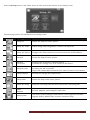
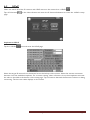
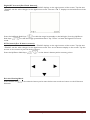
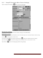
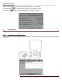
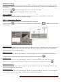
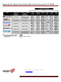
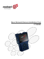
Open Network Camera Installation Tool IT5000 Table of Contents SAFETY WARNING................................................................................................................................................. 1 TABLE OF CONTENTS.......................................................................................................................................... 2 1. INTRODUCTION........................................................................................................................................ 3 1.1 1.2 1.3 1.4 1.5 1.6 1.7 2. 3. 4. TOUCH PANEL CALIBRATION ......................................................................................................... 10 SCREEN LAYOUT .................................................................................................................................... 11 AV IN (ANALOG VIDEO LIVE VIEW) ............................................................................................... 13 4.1 5. 6. 4.2 4.3 4.4 6.1 6.2 6.3 6.4 DOME CAMERA LIVE VIEW .................................................................................................... 13 4.1.1 4.1.2 Enable PTZ Control Function ................................................................................................ 13 Implementing PTZ Control .................................................................................................... 14 FIXED CAMERA LIVE VIEW ..................................................................................................... 15 AV VIDEO SETUP .................................................................................................................... 15 AV DOME SETUP .................................................................................................................... 16 CABLE TEST (CAT5)................................................................................................................................ 17 IP CAMERA LIVE VIEW ........................................................................................................................... 18 CONNECT IP CAMERA (DIRECT CONNECTION)............................................................... 18 DEVICE SEARCH ...................................................................................................................... 19 UPNP ....................................................................................................................................... 21 IP CAMERA SETUP ................................................................................................................... 23 6.4.1 Setup-IP Connection (Alter Camera Settings) .................................................................. 24 6.4.2 Setup-IP Camera (Load the Network Settings) ................................................................ 25 6.4.3 Setup- IP Script (IP Camera API Commands) ................................................................... 25 POWER OVER ETHERNET (POE) ...................................................................................................... 26 7. 7.1 7.2 8. 9. FEATURES ................................................................................................................................... 3 PACKAGE CONTENTS .............................................................................................................. 3 DIMENSIONS .............................................................................................................................. 3 FUNCTIONALITY ....................................................................................................................... 4 PORTABILITY .............................................................................................................................. 6 POWER ON/OFF ....................................................................................................................... 8 BATTERY CHARGE .................................................................................................................... 9 ENABLE POE ............................................................................................................................ 26 POE SETUP ............................................................................................................................... 26 SNAPSHOT ................................................................................................................................................. 28 8.1 8.2 9.1 9.2 IMPLEMENT SNAPSHOT ........................................................................................................... 28 SNAPSHOT SETUP.................................................................................................................... 29 VIDEO RECORDING............................................................................................................................... 30 IMPLEMENT VIDEO RECORDING............................................................................................ 30 VIDEO PLAYBACK ................................................................................................................... 31 10. SYSTEM SETUP .......................................................................................................................................... 32 APPENDIX A ........................................................................................................................................................... 34 APPENDIX B: QUICK START GUIDE..........................................................................................................35 Razberi Technologies Page 2 1. Introduction The IT 5000 Installation Tool is a battery-powered handheld device that greatly simplifies the field installation of network and analog cameras. It connects directly to a camera or network to provide power, discover cameras, and display live video to adjust camera viewing angles and focus. The tool offers a user-friendly touch screen for zooming and programming functions. The IT 5000 is an “open” tool supporting multiple camera manufacturers. 1.1 Features 1.2 Supports multiple camera manufacturers Simplifies camera angle & focus adjustments Powers cameras with PoE (Power over Ethernet) Controls IP and analog PTZs Records snapshots and video clips Capable of field upgrades with new firmware Package Contents (Need images and full list of products) Ensure that the package contains the items listed below. 1.3 Dimensions See the following diagrams for the product dimensions. Razberi Technologies Page 3 1.4 Functionality The product includes the following functions. No. Item Description 1 LAN / PoE Port Connect the LAN cable from the IP camera that is PoE enabled to this port. 2 Power Bank Port The Power Bank provides DC 48V power for the IP camera that is PoE enabled. Before connecting the Power Bank to this port, please set the Power Bank Slide Switch to “On” position. 3 Micro SD Slot Insert the Micro SD card into the slot for data storage. 4 USB Slot Connect the USB storage devices to the slot for firmware upgrade or data storage. 5 Video In Connect the BNC cable to the Video In from the camera. 6 Stylus Touch Pen Slot Use the embedded stylus touch pen for touch screen operation. 7 Power Indicator LED Light LED indicates the power is on. 8 Data TX/RX Indicator LED The LED flashes when the device is under operation. Razberi Technologies Page 4 9 Light Sensor The light sensor on the right above the screen can detect environmental brightness to automatically adjust the LCD screen brightness. 10 3.5” LCD Screen The 3.5” LCD screen displays video and various setup menus. 11 Shift/PTZ Control Keys Press the left/right/up/down arrow keys to navigate among the icons or move through the items within a menu. When viewing the PTZ Camera, users can control PTZ by these keys. 12 ESC Key Press this key to exit without saving or returning to the previous page. 13 Start/Enter/ Snapshot Key Start Function: Turn on the Main Power Slide Switch, and then press this key for about 3 seconds to start up the device. Enter Function: Press this key to enter the sub-menu or to save setup. Snapshot Function: When viewing IP camera video, press this key for image snap shot. Pressing the key and the snapshot setup menu will come out within 5 seconds. Click the “Enter” icon to save the settings of the snapshot image. 14 Main Power Slide Switch Turn on the slide switch before pressing the Start key. 15 Audio Out Plug the headset into the phone jack. 16 Audio In Connect the microphone to the audio input jack. 17 Charging Indicator Light The light will stay on while the device’s battery is charging. 18 UTP Cable For UTP cable test, connect one end of the network cable to this port and the other end to the CAT5 UTP terminator for detecting wiring types (Straight/Cross) or errors (Open, Short, Miss Wired) from the displayed wire map on the screen. 19 DC 12V Power Adapter Connector Connect the supplied DC adapter cord to this DC input jack. 20 RS-485 Terminal Block Connect the RS-485 lines to the terminal block correctly for the Dome Camera’s PTZ control. 21 Loudspeaker For audio output. Razberi Technologies Page 5 1.5 Portability Users can safely carry the IT5000 with the supplied carrying case. Follow the instructions below to use the IT5000 as a portable device. 1. Unzip the carrying case and feed the outward Velcro strap through the inside of the slot located at the bottom of the device. 2. Pull the strap through and stick it securely to the self-adhesive Velcro surface inside the carrying case. 3. Thread the Velcro strap on the edge joint through the inside of the slot located on the top of the device. 4. Pull the strap through and fasten it tightly across the case joint to the Velcro on the opposite side. Razberi Technologies Page 6 5. Lift the front part of the device up and put the sunshade’s short wing into the space between the device and the self-adhesive Velcro surface. Align the wing’s left edge with the left edge of the device. Fasten the short wing to the Velcro surface tightly. 6. Fold one wing around the edge of the device, and insert the tail of the wing into the space between the device and the Velcro surface. Fasten the tail to the Velcro tightly. 7. Repeat steps 5 and 6 using the other wing. Note: Fold the sunshade down to close the case. 8. Hook the carrying case to the neck strap. Slide the clip along the strap to adjust its length. Razberi Technologies Page 7 1.6 Power On/Off To power on the IT5000, set the Main Power Slide Switch to the “ON” position. Press and hold the Start Key for three seconds to turn on the Power Indicator LED. The device begins powering and a loading bar displays on the screen for ten seconds. Note: The Data TX/RX Indicator LED begins blinking. The Home Screen appears within 50 seconds. Razberi Technologies Page 8 1.7 Battery Charge The IT5000 uses a rechargeable Li-ion battery pack. The batter pack charges in approximately four hours and provides the IT5000 with up to three hours of operating life. To open the battery compartment cover, press and push it outward. When installing the battery, ensure that the positioning is correct. The charging indicator light is on during the charging process. The light turns off when charging is complete. Razberi Technologies Page 9 2. Touch Panel Calibration The device is in the Touch Panel Calibration mode for the initial access to the system or when a system reset occurs. Use the following steps to calibrate the system prior to viewing the Home Screen. 1. 2. 3. Tap the flashing cross on the left top of the screen. Hit the flashing cross on the opposite diagonal corner. Touch each flashing box as instructed. The Home Screen displays after completing the calibration. Razberi Technologies Page 10 3. Screen Layout The following icons provide status information. Icon Type Description Battery Status Indicates the battery level and charging status. PSE When the device is connected to an IP camera that is PoE enabled with the device’s PoE function on, the PSE button will be lightened up, and the Camera will drain power from the device’s internal battery. The following buttons are available from the Home Screen. Icon Type Description Home Screen Return to the Home Screen Return Return to the previous page Enter/Save Enter the submenu of a function or to save settings AV In View the video display on the LCD screen via the video output of the BNC supported camera Connect Directly connect to the IP camera with one touch IP camera Access the IP camera menu options Device Search Ideal for testing multiple IP cameras Tap this icon to find all the IP cameras in the network. Select a specific IP camera by IP or MAC from the address list UPnP Tap this icon to find all the IP cameras with UPnP names in the network Select a specific IP camera from the address list Cable Test Detects the CAT5 Cable for wiring types (Straight/ Cross) or errors (Short/ Open/ Miss Wired) Power Over Ethernet Tap this icon to enable Power over Ethernet (PoE) output for IP cameras that are PoE/ PoE Plus enabled PoE Setup Select for PoE setups including Power Level, Power over Ethernet (PoE) measurement, PoE measurement display, Enable PoE when booting, and PoE auto-shutdown time Setup Configure various setups for cameras and the IT5000 Razberi Technologies Page 11 Press the Setup button in the Home Screen to view and use the buttons on the Setup screen. The following buttons are available from the Setup screen. Icon Type Description Setup-AV Access the Setup AV menu options Setup- AV Video Adjust analog video’s brightness, contrast, and sharpness Setup- AV Dome Configure the Dome Camera’s protocol, baud rate, and ID address Setup-IP Access the Setup IP menu options Setup-IP connection Configure the IP camera’s network settings Load relevant settings from an IP camera to the device Setup-IP script Adjust IP camera video’s brightness, color level, contrast, and sharpness by editing the API commands Import the relevant API commands from other IP camera to the device Setup-Snapshot Preview and manage the snapshot files Setup-Video Access the Setup Video menu options Video-Rec Setup Setup the recording video file name, description, and saving path VideoPlayback Preview, playback, and manage the video files Setup-System The device system settings include volume, LCD brightness, firmware upgrade, factory default reset, and auto shutdown setup Razberi Technologies Page 12 4. AV In (Analog Video Live View) View analog video through the BNC IN connector on the top of the device. Connect the BNC cable from the video output connector of the camera to the BNC IN port on the device. Tap the <AV In> button on the Home Screen to view live video on the LCD screen. To view live video from an IP camera which supports BNC via AV In function, confirm the IP camera streaming is set as “BNC Out.” 4.1 Dome Camera Live View Implement a dome camera’s PTZ control in the live view mode. NOTE: Confirm the dome camera’s RS-485 lines are correctly connected to the device’s RS-485 terminal block. 4.1.1 Enable PTZ Control Function Tap the <Setup> button on the Home Screen and then tap <AV In> Razberi Technologies to enter it. Page 13 Tap <Setup-AV Dome> and enter its settings. Select <Enable> from the <Dome type> drop-down list. Tap <Enter/Save> system automatically returns to the previous screen. Tap <Return> 4.1.2 to save the settings, and the to return to the Second Screen. Implementing PTZ Control Tap <AV In> screen. button in the Home Screen to enter the live view mode. Four arrow buttons display on the Tap the arrows on the screen to pan and tilt the camera. Press the Up/Down Shift Keys ( device’s button pad for zooming in/out. ) on the Adjust video brightness, contrast, or sharpness for different live viewing quality in the <Setup-AV Video> function which can be accessed by the following path: Setup> Setup-AV> Setup-AV Video. Razberi Technologies Page 14 4.2 Fixed Camera Live View In the Fixed Camera’s live view mode, the TV System (NTSC/PAL) of the camera displays on the left bottom of the screen. Adjust video brightness, contrast, or sharpness for different live viewing quality in the <Setup-AV Video> function, which can be accessed by the following path: Setup> Setup-AV> Setup-AV Video. 4.3 AV Video Setup The <Setup-AV Video> can be accessed by the following path: Setup> Setup-AV> Setup-AV Video. In the <Setup-AV Video> menu, adjust analog video’s brightness, contrast, or sharpness. Access <Step- AV Video> Tap <Setup> on the Home Screen. Tap <Setup-AV> Video> to enter the settings page. to enter the AV Setup Screen. Tap <Setup-AV In the <Setup-AV Video> setting page, the live video displays on the upper screen. Adjust Brightness/Sharpness/Contrast Value Move the slider bar by touching the screen or using the device’s Left/Right Shift Keys ( Razberi Technologies ). Page 15 Switch to another Item Tap the <AV Mode> icon next to the slider bar or press the device’s Up/Down Shift Keys to switch among Brightness, Sharpness, and Contrast settings. Tap <Enter/Save> automatically return to the previous page. Tap <Return> 4.4 to save all the settings and to exit the settings page without saving settings. AV Dome Setup In the <Setup-AV DOME> menu, enable/disable PTZ controls and configure the dome camera’s protocol, baud rate, and ID address. Access <Step- AV Dome> Tap <Setup> on the Home Screen. Tap <Setup- AV> AV Dome> to enter the settings page. to enter the AV Setup Screen. Tap <Setup- Set the Dome Type Select <Enable> or <Disable> from the drop-down list of the <Dome Type>. <Enable> activates PTZ control on the device; <Disable> indicates disabling PTZ controls on the device. Set the Protocol Select the protocol for the dome camera from the drop-down list. Set the Baud Rate Select the baud rate for the dome camera from the drop-down list. Set the ID Address Enter the three-digit ID address. Tap <Enter/Save> to save all the settings and return to the previous screen. Tap <Return> the settings page without saving settings. Razberi Technologies to exit Page 16 5. Cable Test (CAT5) Check the RJ-45 cable wiring with the supplied UTP Terminal Block. Setup for Testing Connect one end of the RJ-45 connector to the UTP Terminal Block and the other end to the CAT5 port at the side of the device. Cable Testing Tap the <CAT5> Tap <Test> icon on the Home Screen. and wait for wiring detection. The cable’s wire map displays on the screen. Check the RJ-45 cable for its wiring type (Straight/Crossover) and error connection (Shorts/ Open/ Miss Wired). Tap <Return> to return to the Home Screen. Razberi Technologies Page 17 6. IP Camera Live View The device automatically detects and recognizes the IP camera that is connected to it. Connect the IP camera to the device’s LAN port; plug in the IP camera if not using PoE. Automatically Chang the Device’s IP Address After turning on the IP camera, the device automatically detects the IP address and displays it on the screen. 6.1 Connect IP Camera (Direct Connection) Setup for Direct Connecting Tap the <IP Camera> icon on the Home Screen to enter the submenu. Check the IP Camera Profile in the field under the <Connect> icon. The IP camera’s profile details include IP address, camera type, username, and password. The device connects immediately to the camera and provides live video. Information appears after connecting the device to the camera. To alter any of the settings, access the Setup-IP menu. Access the Camera Tap the <Connect> icon on the IP Camera Submenu. The live video displays on the LCD screen. Digital PT Control (For Fixed Camera) In the IP camera’s live view mode, the text “ZOOM” displays on the right bottom of the screen. Tap the text “ZOOM” and the video changes to the digital zoom mode. The text “P & T” displays on the left bottom of the screen. Razberi Technologies Page 18 Press the Left/Right Shift Keys ( ), to horizontally shift the image to the left/right. Press the Up/Down Shift Keys ( ), to shift the image upward/downward. Tap “ZOOM” or “Esc” to leave the Digital PT Control mode. Exit the Viewing Mode Press the ESC Key Submenu. 6.2 on the device’s button pad to exit the live view mode and return to the IP Camera Device Search If there are multiple IP cameras in the network, use the <Device Search> function to search for cameras. Access <Device Search> in the IP Camera Submenu. Implement Device Search Tap the <Device Search> icon to enter the Device Search page. Select the target IP camera from the device list on the left top of the screen. Select the camera connection duration from the available dropdown. For a custom setting, select <Custom> from the dropdown and enter the value in the field at the bottom of the setup page. Tap <Connect> beneath the Password column to being connecting. The live view video displays on the screen. Razberi Technologies Page 19 Digital PT Control (For Fixed Camera) In the IP camera’s live view mode, the text “ZOOM” displays on the right bottom of the screen. Tap the text “ZOOM” and the video changes to the digital zoom mode. The text “P & T” displays on the left bottom of the screen. Press the Left/Right Shift Keys ( ) to shift the image horizontally to the left/right. Press the Up/Down Shift Keys ( ) to shift the image upward/downward. Tap “Zoom” to leave the Digital PT Control mode. PTZ Control (For IP dome camera) In the IP camera’s live view mode, the text “ZOOM” displays on the right bottom of the screen. Tap the text “ZOOM” and the video changes to the digital zoom mode. Four arrow buttons display on the screen. Tap the arrows on the screen to pan and tilt the camera. Press the Up/Down Shift Keys ( ) on the device’s button pad for zooming in/out. Exit the Viewing Mode Press the ESC Key Submenu. on the device’s button pad to exit the live view mode and return to the IP Camera Razberi Technologies Page 20 6.3 UPnP Users can search all of the IP cameras with UPnP names in the network via <UPnP> Tap <IP Camera> page. . on the Home Screen and enter the IP Camera Submenu to access the <UPnP> setup Implement UPnP Tap the <UPnP> icon and enter the UPnP page. Select the target IP camera from the device list on the left top of the screen. Select the camera connection duration from the available dropdown. For a custom setting, select <Custom> from the dropdown and enter the value in the field at the bottom of the setup page. Tap <Connect> beneath the Password column to being connecting. The live view video displays on the screen. Razberi Technologies Page 21 Digital PT Control (For Fixed Camera) In the IP camera’s live view mode, the text “ZOOM” displays on the right bottom of the screen. Tap the text “ZOOM” and the video changes to the digital zoom mode. The text “P & T” displays on the left bottom of the screen. Press the Left/Right Shift Keys ( ) to shift the image horizontally to the left/right. Press the Up/Down Shift Keys ( ) to shift the image upward/downward. Tap “Zoom” to leave the Digital PT Control mode. PTZ Control (For IP dome camera) In the IP camera’s live view mode, the text “ZOOM” displays on the right bottom of the screen. Tap the text “ZOOM” and the video changes to the digital zoom mode. Four arrow buttons display on the screen. Tap the arrows on the screen to pan and tilt the camera. Press the Up/Down Shift Keys ( ) on the device’s button pad for zooming in/out. Exit the Viewing Mode Press the ESC Key Submenu. on the device’s button pad to exit the live view mode and return to the IP Camera Razberi Technologies Page 22 6.4 IP Camera Setup Access the Setup-IP Submenu to change the IP camera’s settings. Access <Setup- IP Connection> and <Setup- IP camera> Tap the <Setup> Tap <Setup-IP> icon on the Home Screen. to enter the IP Setup Submenu. The <Setup-IP Connection> icon and <Setup-IP Camera> Razberi Technologies icon are in the IP Setup Submenu. Page 23 6.4.1 Setup-IP Connection (Alter Camera Settings) Tap the <Setup-IP Connection> icon to enter the setup page. Specify Camera Settings Specify the necessary information for the camera’s settings in the available fields. Add a Camera to List To add a camera to the Camera Profile list, enter the model name in the <Camera Profile> column and tap the icon on the right side of the column. To cancel a camera, select the camera and tap the icon Tap <Enter/Save> Tap <Return> . Assign up to 128 IP cameras for testing. to save all the settings and automatically return to the previous screen. to exit the settings page without saving settings. Razberi Technologies Page 24 6.4.2 Setup-IP Camera (Load the Network Settings) Access the Setup-IP Camera> Tap the <Setup-IP Camera> page to check or alter the IP camera’s network settings. icon and enter its setup page. Load Settings from the IP Camera Tap the <Load from Camera> button on the top of the menu and the IP camera’s network settings display in the blank field. NOTE: Confirm the target camera’s settings are correctly configured. To alter the camera settings, tap the <Return> the camera settings. button and enter the <Setup-IP Connection> to change Reload the Settings to the IP Camera After making network setting changes, tap the <Set to Camera> button on the top of the setup page to reload the network settings to the camera. Tap <Enter/Save> Tap <Return> 6.4.3 to save all the settings and return to the previous screen. to exit the settings page without saving settings. Setup- IP Script (IP Camera API Commands) Tap the <Setup- IP Script> icon to enter the setup screen. This script tool can be used to set any of the API commands supported by the IP camera. The unit is supplied with a default set of commands already loaded, but these can be replaced or added to as required. It is also possible to create/edit a script on a PC and then tap the <Import> button to load it via a USB stick (name the file script.txt). Tap the <Save> button to save the settings. Tap <Enter/Save> Tap <Return> to save and return to the previous screen. to exit the settings page without saving the settings. Razberi Technologies Page 25 7. Power over Ethernet (PoE) The IT5000 functions as the power sourcing equipment (PSE) and provides power to IP cameras that are PoE/ PoE Plus enabled. 7.1 Enable PoE Connect the Ethernet cable from the IP camera to the LAN/PoE OUT Port on the side of the device. The power switch located next to the LAN/PoE port must be “OFF.” Tap the <PoE ON> icon on the Home Screen to enable the PSE. The PSE indicator light comes on when the device provides power to the IP camera. The <PoE ON> icon turns into <PoE OFF> the PoE function. 7.2 when the PoE is enabled. Tap <PoE OFF> to turn off PoE Setup Tap the <PoE Setup> icon on the Home Screen. Razberi Technologies Page 26 Power Level Set the output Power Consumption Level range according to specific requirements. NOTE: Confirm the PoE function is off prior to adjusting the Power Level settings. PoE Measurement Select from the <PoE Measurement> dropdown to display the PoE Measurement information. PoE Measurement Display Select from the <PoE Measurement Display> dropdown to display PoE Measurement information. Enable PoE after device Bootup Select <ON> from the <Enable PoE when booting> dropdown to configure the device to provide power to the IP camera after system startup. Razberi Technologies Page 27 PoE Auto-shutdown Select the PoE auto-shutdown interval. Setting the device to an automatic shutdown interval attributes to battery conservation. A reminder displays five seconds prior to shut down. Tap <Enter/Save> Tap <Return> 8. to save the settings and return to the Home Screen. to exit the settings page without saving the settings. Snapshot The Snapshot function facilitates saving images in the assigned path when necessary. 8.1 Implement Snapshot In the IP camera’s live view mode, press the <Snapshot> key on the device’s button pad to enter the Snapshot setup page. Razberi Technologies Page 28 Snapshot File Setup Assign a storage location from the three options (Tester / USB/ SD) located at the very top of the snapshot setup page by tapping the round button on the left side of the option. Enter the file name and description for the snapshot. Tap <Enter/Save> Tap <Return> to save the settings and return to the live view mode to exit the setting page without saving settings. Files in USB/SD Files saved to the USB drive or Micro SD card automatically save in the “IMAGE-DATA” folder. Each snapshot’s description is located in the attached .txt file. 8.2 Snapshot Setup Preview, copy, and delete images on the <Setup-Snapshot> setup page. Tap the <Setup> managing page. icon on the Home Screen and tap on <Setup-Snapshot> to enter the snapshot file Image Preview On the <Setup-Snapshot> page, select the snapshot storage path (Tester / USB/ SD) where the saved files are located. The files appear in a list in the <File List> field. To view a snapshot, tap the file name in the list and the image appears in an <Image Preview>. Single File Copy Tap the file name in the list to copy a single file. Tap the <Copy> icon in the <File Manager> section below <Image Preview>. Select the copy location in the window and tap <Enter/Save> . All Files Copy Tap the <Select All> icon in the <File Manager> section to select all the files in the <File List>. Tap the <Copy> icon to copy all the files. Select the copy location in the window, and tap <Enter/Save> . Single File Deletion Tap the file name in the list to delete a single file. Tap the <Delete> icon in the <File Manager> section. Tap <OK> in the window to delete the file. All Files Deletion Tap the <Select All> icon in the <File Manager> section to select all the files in <File List>. Tap the <Delete> icon to delete all the files. Tap <OK> in the window to delete all selected files. Razberi Technologies Page 29 9. Video Recording The device supports Video Recording, Video Setup, Video File Managing and Video Playback functions for IP camera live views. 9.1 Implement Video Recording In the IP camera’s live view mode, tap the white text “REC” on the right top corner of the live view screen to start Video Recording. During the recording process, the text appears in red. Tap the text “REC” one more time to stop Video Recording and the returns to white. Video Recording Setup (Video- Rec Setup) Tap the <Setup> icon on the Home Screen. Enter <Setup- Video> by tapping the icon. Tap <Video- Rec Setup> on the Video Setup Screen to access the video recording setup page. Assign a storage location by tapping the round button on the left side of the available options. The three options (device/ USB/ SD). Enter the file name and description for the snapshot. Tap <Enter/Save> to save all the settings and return to the live view mode. Tap <Return> settings page without saving. Razberi Technologies to exit the Page 30 9.2 Video Playback Users can preview, copy, and delete the video on the <Video- Playback> page. Tap the <Setup> icon on the Home Screen and tap <Setup- Video> Tap <Video- Playback> to access video play back page. to enter the Video Setup Screen. Video Playback On the <Setup-Snapshot> page, select the recording video storage path (Tester / USB/ SD). The list of video files appears in the <File List> field. To view a video, tap the file name in the list and tap the <Playback> button on the bottom. The video appears as full screen. In the Video Playback mode, press <ESC> to stop playback and return to the video playback page. Single File Copy Tap the file name in the list to copy the file. Tap the <Copy> icon in <File Manager> section. Select the copy location in the window and tap <Enter/Save> . All Files Copy Tap <Select All> in the <File Manager> section to select all the files in <File List>. Tap <Copy> to copy all files. Select the copy location in the window and tap <Enter/Save> . Single File Deletion Tap the file name in the list to delete the file. Tap the <Delete> icon in the <File Manager> section. Tap <OK> in the window to allow file deletion. All Files Deletion Tap <Select All> icon in the <File Manager> section to select all the files in <File List>. Tap <Delete> to delete all the files. Tap <OK> in the window to confirm. Razberi Technologies Page 31 10. System Setup Use the system setup page to adjust the volume or brightness of the LCD screen, implement firmware upgrades, restore system settings to factory defaults, and select an auto shutdown time. Access <Setup- System> Tap the <Setup> icon on the Home Screen. Tap the <Setup-System> icon to enter the system setup page. Adjust device Screen Brightness (Backlight) Move the slider bar to adjust the <Backlight>. Tap the <Auto Control> box to lock the level on the slider bar. Tap the <Auto Control> box again to cancel the selection. Razberi Technologies Page 32 Upgrading Firmware Before proceeding with the upgrade, download both upgrade files from http://www.razberi.net/products/accessories/it-5000/. Then place the upgrade files within the following folder structure E:\upgrade\upd_razberis on a USB thumb drive. Note: For units being upgraded from version 476 and above, the files can be stored at the root (E:\) directory of the thumb drive. Access <Setup- System> Tap the <Setup> icon on the Home Screen. Tap <Setup-System> Select <Upgrade> Tap <USB> The firmware details will display in the blank field of the file selection menu. Check the <Complete upgrade> box and tap <Enter/Save> the upgrade and continue. to start the upgrade. Tap <OK> to confirm Reset to Factory Defaults Users can restore the device to factory defaults if necessary. Tap the <Default> button. Tap <OK> in confirmation prompt to continue. Tap <OK> to reboot the system. The device shuts down and restarts. The device must be calibrated upon reset. Auto Shutdown The system automatically shuts down after a pre-determined time range when idle. Select the specific time interval from the dropdown for auto shutdown. To disable the <Auto Shutdown> function, select <OFF>. Razberi Technologies Page 33 Appendix A Display Color LCD Field Display Resolutions 3.5”, automatic aspect ratio adjustment 320x240 Connectors Video Input BNC Video In, RJ-45, RS-485, CAT-5, USB 2.0, PoE 10BASE-T/100BASE-TX PoE IEEE 802.3at Video Image Settings PTZ Control Autosensing Brightness, Color Level, Contrast RS-485 RS-485 Ports PTZ Camera Settings R+, R-, T+, TPan, Tilt, Zoom, Manual Focus, Auto Focus AD422, DSCP, Dynacolor, Fastrax 2, JVC, Molynx, Optix, Panasonic_C, Panasonic_N, Pelco D, Pelco P, Sensormatic Signal Format NTSC / PAL Video Level IVpp, 140IRE Supported PTZ Protocols Video IP Camera LAN In 10/100 Mbps, 48VDC In, Power Bank In LAN Out 10/100 Mbps, 802.3at standard IP Camera Settings IP Address setting, Image Setting ACTi, AMTK, autoIP, Axis, Arecont Vision, D-Link, DVTel, Dynacolor, eVidence, HikVision, IQinVision, ONVIF, Optix, Panasonic, Planet, razberi™, Sanyo, Siqura, Sony, SPECO, Vivotek, XVISION, ZAVIO Camera Support Operation Weight (Battery included) 0.99 lb (450 g) Dimensions (LxWxH) 170x99x38 mm Battery Type 2 x 3.7 V Li-Ion, 2000mAh Charging Cycles/Time 80% capacity after 300 charge cycles / 3.5 hours Operating Time 3 hours with PoE off / 2 hours with PoE on Temperature: 32° F to 122° F Humidity: 20-80% RH (non-condensing) Operating Conditions Network IP Setting Application Programming Interface DHCP, Static IP address Open API for software integration General Specifications Casing Included Accessories Regulatory Memory Input Voltage Storage Input Audio Output Bypass / Power Bank PoE Device ABS Plastic, Color: Blue Carrying case w/sunshield, protective rubber sleeve, stylus pen, UTP terminal block, Ethernet cable, BNC cable, car charger, 12V DC power supply CE, FCC 128 MB RAM (16 MB available for snapshots) DC12V, 5A MicroSD Card supported (card not included) Line In Built-In Speaker, Phone Jack Φ3.5 PoE/PoE Plus LAN In Internal Battery Razberi Technologies Page 34 Appendix B: Quick Start Guide (Directly Connected To IT-5000) © 2012 razberi™ Technologies; v3.08.12 www.razberi.net Razberi Technologies Page 35