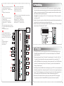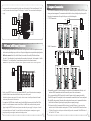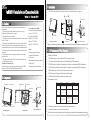
1
3.Installation
inBIO26 0 Installation and Connection Guide
After the following installation, fix the panel to the track first, and then install other components.
Version: 1.3 Date: Jan. 2014
Screws
Control Panel
1.Cautions
Please note the follo wing cautio ns. Mis-operatio n may lead to personal injury or
equipment failu re:
1)Do not energize the system before installa tio n is complete; never carry out
installa tio n activ itie s when the system is energized.
2)All perip heral devices must be grounded.
3)The conduits of wire s under relay must be matched with metaled conduits , other wire s
can use PVC conduits .
4)It is stro ngly recommended that the length of exposed part of any connectio n cable
should not be longer than 4 mm. Professional clamping tools may be used to avoid
unintentio nal contact of exposed wire s to avoid short- circ uit or communicatio n failu re.
5)It is recommended that card readers and butto ns be installe d at height of 1.4m-1.5m
above ground.
6)It is recommended to use the power supply for contro l panel, and external power
supply for each lock.
7)The applia nce shall be installe d and wire d in accordance with natio nal electric al
code and by qualifie d personnel only
Descriptio n of normal working state:
Connect the system to the power supply. If the system works properly, the POWER
indicator (red) is lit constantly and the RUN indicator (green) fla shes.
Valve regulated lea d-ac id battery :
Constan t voltage charge voltage reg ulati on
Cycle use : 14.5V ~14.9V (25 )
Initial curren t: less tha n 2.88 A
Stan dby use: 13.6V ~13.8V (25 )
Capacity: 12V, 7.2A h/20 hr,
Battery Type: LC-RA127R2T1
Panel Track
2
Thread holes
1) Get through the thread hole
Box Lock Hole
1) Meaning of LED indicators:
LINK indicator (green): Constant light indicates TCP/IP communication is normal.
ACT indicator (yellow): Flashing indicates data is transmitting through TCP/IP communication.
EXT RS485 indicator (yellow&green): Flashing indicates it is sending or receiving data through RS485 communication.
PC RS485 indicator (yellow&green): Flashing indicates it is sending or receiving data through RS485 communication.
POWER indicator (red): Light always indicates the control panel is power on.
Backup Battery
Interface
Power (A)
Control Panel
Wiegand (B)
Control Panel
Electric Lock (C)
1
Button (D)
Air Switch
EXT485 (E)
2
Heat
Dissipation Hole
Panel Box Appearance
3) Install other components
RUN indicator (green): Flashing indicates that system is working normally.
CARD indicator (yellow): Flashing indicates card is punched on reader.
2) Recommended use of wires:
Temper Switch
Thread Hole
2) Fix the box
4.LED Indicators and Wire Illustration
Caution :
Do not charge in a gas tight containe r.
Do not short the battery term ina ls.
Do not inc ine rate
Flush with water at once if contact is made with
elec trolyte (Acid )
Do not attem pt to disasse mble the battery .
2.Components
State Indicator
1
Panel Track
Power Supply
Panel Box Inside
Wire Specification
18AWG*2PIN
24AWG*6PIN
(6PIN, 8PIN, 10PIN for different
readers)
18AWG*2PIN+24AWG*2PIN,
18AWG*2PIN for lock connection,
24AWG*2PIN for door sensor
connection.
24AWG*2PIN
Network cable
Maximum length
/
1.5M
CAT-5 or above network cable, one
way DC impedance is less than 100Ω 100M
/KM
/
/
CAT-5 or above network cable, one
20AWG*2PIN+24AWG*2PIN,
way DC impedance less than 100 Ω
20AWG*2PIN for reader power
/KM. In wire connection, +12V and
supply, 24AWG*2PIN for RS485
GND of power supply need to be
communication
parallel and use double wires.
50M
100M
Share power with control panel: 100M
Use independence power supply
(connect RS485 signal interface only):
1000M
3) The auxiliary input may be connected to infrared body detectors, alarm switches, etc.
4) The auxiliary output may be connected to door bells, alarms, etc.
5) State Indicators are connected to the panel box, which is power indicator, run status indicator and communication status indicator.
Get the Panel off the track
1
2
1
AUX Output (1-2) connect to alarm, door bell and so on;
Port (NO,COM,NC) Electrical Parameters:
MAX Voltage: 36V(DC)
MAX Current: 1.25A
Note:
AUX Output (1-2) connect way is same.
6
2
Lock (1-2):
Port (SEN)connect to door sensor single with
dry contact (no voltage);
Port (NO, COM, NC) Electrical Parameters:
MAX Voltage: 36V(DC)
MAX Current: 2A
Note:
When you select Wet mode, the power is Lock power,
Lock (1-2) total load don’t more than Lock power Rated
current (2A).
Lock (1-2) connect way is same.
7
Exit button for Lock (1-2) connect to Exit button with dry contact.(no voltage);
Reader (1-2) connect to WG Reader;
Port (+12V)Output Electrical Parameters:
Rated Voltage: 12V(DC)
Rated Current: 0.5A
Port (BEEP GLED) Output Electrical Parameters:
Rated Voltage: 5V(DC)
Raged Current: 0.5mA
SD Card Interface.
Function:
Backup Access
Control Logs
4
O
N
LINK
2
3
4
5
6
7
8
SGN D
EXT
RS485
32
16
8
4
2
1
5
SWITCH
RS485
Reader
PWR
STATE
RS485
Converter
EXT
RS485
Reader for B
7
Lock 1
PC
RS485
2 C Lock 2
Power
3 A Lock
Input
Restore Factory Settings
6.Lock Connection
Reader for B
7
Lock 1
1) The control panel provides lock control output interfaces. For NO lock, it is normal open when power is on, so
COM and NO terminals should be used. For NC lock, it is normal closed when power is on, so COM and NC
terminals should be used.
2) The control panel supports “dry mode” and “wet mode” by using the jumper. For “wet mode”, short 2-3 and
4-5 terminals. The control panel and the lock use separate power supplies: One is connected with +12V
and GND of POWER interface (for the control panel), the other is connected with V+ and V- of LOCK interface
1 D AUX Output 2
2 C Lock 1
RS485 Terminal Resistance
State Indicator
Exit Button for D
6
Lock 1
SGND
1 D AUX Output 1
E
PC
RS485
AUX Input 2
DIP Switch
PC
1
AUX Input 1 D 5
PC Network
Interface
ACT
Note:
Output Electrical Parameters:
Rated Voltage: 12V(DC)
Rated Current: 0.5A
PWR
STATE
Lock Power Input Electrical Parameters:
Rated Voltage: 36V(DC) Rated Current: 2A
Device Power Input Electrical Parameters:
Rated Voltage: 12V(DC) Rated Current: 2A
1) Switches 1-6 are used to set the control panel number in RS485 communication: It is adopted binary coding and
little endian, the address number setting by placing these 6 switches as shown in the figure below. Before setting
the address, please keep the system powered off. Place the corresponding switches to the desired status, and the
address number should not be repeated in the network.
For example: Set the device number as 39 (39=1+2+4+32), the switches status are 111001, that is set number 1, 2,
3 and 6 switches at “ON”.
2) Number 7 switch is used to restore factory defaults: Switch it for three times within 10 seconds and restart the device,
then all data will be cleared and the system restored factory default setting.
3) Number 8 switch is used to set terminal resistance in RS485 communication: Switch it to“ON” status, for adding a
terminal resistance of 120 ohm between 485+ and 485-.
SWITCH
3
5.DIP Switch Settings
5
AUX Input (1-2) connect to the infrared human
body induction, wireless exit button, windows
sensor with dry contact (no voltage).
AUX Input (1-2) connect way is same.
Exit Button for D
6
Lock 2
(for the lock). For detailed settings of “dry mode” and “wet mode” , please refer to the Installation Guide.
The factory default is dry mode.
3) For the Wiegand reader and the inBIO reader, t he standard power supply is 12V/3A. So we do not recommend that
lock and the control panel share a common power supply. If it is necessary to do so we suggest using a larger one
such as 12V/5A.Not including the power reserved, there are 2A current for the lock. For the common electrical
lock (the standby current is 300mA, the max current is 500mA), the maximum connected lock is 4.
4) When electrical lock is connected with access control system, you need to parallel a Fr107 diode (equipped
in the package) to prevent the self-inductance EMF affecting the system, do not reverse the polarities.
Reader for B
7
Lock 2
4 A Power Input
Reader for B 7
Lock 2
3
4
8.Equipment Communication
Insert a screw driver to the rectangular hole in the four corner of the panel back. Push it in until hearing the "click"
sound. Then remove the case from the panel. The following is “wet mode” lock connection with external power
supply.
The PC software can communicate with the panel according to the communication protocols (RS485 and TCP/IP) for data
exchange and remote management. The communication cable should be as far away from high-voltage lines as possible.
Do not keep the communication cable in parallel with power cords or bind them together.
1. TCP/IP Communication
Switch
FR 107
LOCK
+
-
Enlarged diagram
of lock terminals
Diode
-
SEN
+
LED
GND
NO Lock
NO
1
PWR
SGND
SGND
EXT
RS485
EXT
RS485
EXT
RS485
PC
RS485
PC
RS485
PC
RS485
-
7.485 Reader (inBIO Reader) Connection
PWR
STATE
SGND
NC Lock
PC
SWITCH
PWR
STATE
-
SWITCH
Jumper
terminal
+
8# Control Panel
2# Control Panel
STATE
Lock Power
FR107
SWITCH
+
NC
+
LOCK
-
1# Control Panel
2
3
4
5
COM
Diode
2. RS485 Communication
The control panel supports inBIO biometric verification reader and Wiegand reader. All inBIO reader operations are executed
from the control panel including storage, verification, etc. Re-register the fingerprints is not required when replacing the reader.
inBIO reader connection: First of all, set the 485 address (device number) of the reader by DIP switch and software.
For reader 1, 2 (the odd number is for entered reader, and the even number is for exit reader), the door number is 1. And the
485 address is 1, 2, as in the figure below. For more information, please refer to the software user manual.
GND
485-
485+
Serial Bus
485+
Attention: DIP switch configuration for FR1200, KR500E&M-RS; Software configuration for unnormalized F11,MA300 and other fingerprint readers.
485+
485+
485-
485-
485-
GND
GND
GND
2# Control Panel
1# Control Panel
PC
8# Control Panel
N 1
PWR
PWR
STATE
STATE
2
SWITCH
SWITCH
PWR
STATE
STATE
GND
+12V(Separate power supplies)
SWITCH
GND
+12V(Separate power supplies)
O
SWITCH
GND
485485+
PWR
485
Converter
3
EXT
RS485
SGND
SGND
SGND
EXT
RS485
PC
RS485
PC
RS485
PC
RS485
5
EXT
RS485
PC
RS485
4
EXT
RS485
PC
6
7
8
DIP Switch
#1 Reader
#2 Reader
#3 Reader
#4 Reader
1) Internationally accepted RVVP (shielded twisted-pair) wires should be used for communication to effectively avoid
interference. RS485 communication wires should be connected by means of bus cascade connection.
2) It is recommended that the RS485 bus should be less than 600 meters to help aid communication stability.
3) One RS485 bus may hold 63 control panels, but it is not recommended to connect with less than 32 access control panels.
4)For the inBIO reader connection, if the reader and the control panel use the same power, it is recommended that the wire
should be less than 100 meters. If greater length is required, please use a separate power supply.
5) To enhance the stability of communication When the wire is longer than 300 meters, i t is necessary to keep
number 8 switch of the first and the last control panel at “ON” status. That adds the RS485 terminal resistance
(120 ohm) of the two devices to the system. As shown in the figure above, turn number 8 of the DIP switches of
the 1# and 8# at "ON” status.
Besides, a single EXT485 interface can supply maximum500mA(12V) current . So the entire cuttent consumption
should be less than this max value when the readers share power with the panel.
In calculation, please use max current of the reader, and start current is usually more than twice of normal
work current, please consider of this situation.
For example, use the FR1200 reader , the standby current is less than 100mA, the max current is less than 120mA, When
the device is start, Instantaneous current can reach 240 mA. As inBIO reader, consider the starting current is
bigger, through the EXT485 interface can only c onnect two readers for power supply. So the power of control
panel connect only nearest 2 readers. For some of the devices with much greater consumption, we suggest to
using the separately power supplies, to make sure the steady operation.
5
6