1
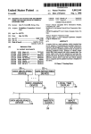
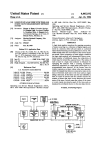
15180057988 I 8A 1
United States Patent [19]
[11] Patent Number:
[45] Date of Patent:
Derderian et a].
5,798,818
Aug. 25, 1998
[54]
CONFIGURABLE CINEMA SOUND SYSTEM
5.386.255
1/1995 Beard et a1. .............................. .. 352/5
[75]
Inventors: Ara J. Derderian. Alta Lorna; Daniel
5-450J4'5
5.386.256
9/
1/1995
1995 Taylor
Chedevine
et a].e‘ 31
5.617.158
5.550.603
8/1996 Miyamori
4/1997
Yoshimuraetet a1.a1.
J_
Embree
lv?near~Irving
Westminster.
James Paul
1“ems
M_
Huntington Beach all of Calif_
‘
Primary Examiner—Safet Metjahic
.
_
Assistant Examiner—John Chizmar
i731 Asslgnccs- at; rizlérlf?lqn- T311206 ‘fffgnbistiymy
Atmme); Agent, or Firm—Jerry A. Miller
Calif.
[57]
_
ABSTRACT
A theater sound processing system that provides preset
[2]] Appl' N0" 940’7'47
con?gurations including parameters that can be modi?ed by
[22] Film;
a user. Other setup parameters are modi?able by the manu
Sep' 30, 1997
facturer or a third party such as a sound technician who
Related US. Application Data
[63]
[51]
52
[
]
provides such parameters at installation time. The param
eters allow control of equalization settings. gain. noise
Continuation of Ser. No. 544353, Oct. 17, 1995. abandoned.
Int C16
G03B 31/04
U S Ci ................................................. 3.52/31. 352/11
‘..
. ............................................... ..
of Search .................................... ..
,
[56]
reduction processing. surround sound processing. and other
audio characteristics. The designation of user modi?able
Parameters and nomuscr modi?able param?tcrs insures that
,
the user is given Safe control Over nec?ssary pans of the
system- US€[_modi?able para-‘Haters ar? changed via a “S61.
interface. Other parameters can be transferred to the sound
11.
References Clmd
US‘ PAIENT DOCUMENTS
processing system via a portable computer or by commu
nications link. In a digital sound processing embodiment of
the invention the entire sound processing ability of the
system can be updated by downloading new signal process
15221525582031!‘ """""""""""""" "
4,3s5:s14
5,155,510
5,280,314
5/1983
Elliot . . . . . . . . . . . .
. . . . ..
10/1992 Beard
352/92
mg 50mm‘
.... .. 352/27
1/1994 Hymes
352/129
26 Claims, 10 Drawing Sheets
v/ 100
Projector
(
Pro}. 1
)
19A
CD Player
PTO].\2
_
Digital Cinema
Sound Processor
m
i
L
C
SL
F1
SR
SW
US. Patent
Aug. 25, 1998
Sheet 1 0f 10
5,798,818
FIG. 1
f 100
Audio Signal
m
Digital Cinema
Sound Processor
125
L
c
SL
n
SRI
SW
U.S. Patent
Aug. 25, 1998
Sheet 2 0f 10
5,798,818
JTBTQTETKHETZI
4J ‘aQ tug‘5221q8m%2.5
if4J.5
mmgAlm.A%EOEI‘wid.
4%.‘Elm .5‘
‘Elm
638052
3@986w5 %
GI
N
29.
M
64
8%92 m3
0mm295 3A
Em
U.S. Patent
Aug. 25, 1998
588-.w-.0m8
“2:2
.825:2B Wm,“
Sheet 3 of 10
5,798,818
U.S. Patent
Aug. 25, 1998
-|FLm.
Sheet 5 0f 10
5,798,818
i1
"
_
§Q3.
_
gm3H“
TT
"I
n
m
_
_
_
n_2N95m5252:538mag:20
M
.New
EN
2m
_
_n2N0.35252:985:20
_"
gm
_
@m
_2Nn‘LI.625o<a92:58#82:2.0?‘
n
>
n08:25 n
u
g
Il2E_
—lm
"Igor:0 a: wlwig
_6=€<nA2mN|m956aEck:25m_co50um|
_
n
n
Il‘-u'
US. Patent
Aug. 25, 1998
5,798,818
Sheet 8 0f 10
62%
wow
AV)
“m8212:.3?
6E
w
631NENS-we‘
2$05m8;
.wEms_<mz
685
N-
w
Emmi- 6.85
v
m- 685
Emmiw
l
Noovmcohm
US. Patent
Aug. 25, 1998
Sheet 9 of 10
5,798,818
62%
omw\
.QE
@
2%E.w
\ $m
_l|
US. Patent
Aug. 25, 1998
Sheet 10 0f 10
5%
mmw
.GEor
5u2.m“:5.8
05m0528m5%
520E039m5»9m,2$8
0mm
0
#
$3 :6
5,798,818
5.798.818
l
2
CONFIGURABLE CINEMA SOUND SYSTEM
standards are Dolby Type A and Dolby Spectral Recording
(“SR”). Systems that implement these noise reduction stan
This is a continuation of application Ser. No. 08/544353
?led on Oct. 17. 1995 now abandoned which is hereby
dards modify the sound before it is recorded
(“compression'”) and reverse modify the sound before it is
incorporated by reference.
played through the speakers so that only the original sounds
are heard (“decompression”).
SOURCE CODE APPENDIX
Aproblem faced by theater sound system operators is that
sound playback modes often differ from movie to movie. For
A micro?che appendix of computer language source code
for a preferred embodiment (@ 1995 Sony Corporation) is
?led herewith. A portion of the disclosure of this patent
document contains material which is subject to copyright
protection. The copyright owner has no objection to the
facsimile reproduction by anyone of the patent document or
the patent disclosure as it appears in the Patent and Trade
mark Office patent ?le or records. but otherwise reserves all
example. one movie may be in stereo while another is in a
surround sound playback mode. Further. the playback mode
may be coupled with a noise reduction standard so that the
appropriate sound decompression circuitry must be selected
for proper sound reproduction. Another important aspect in
a listener’s perception of the quality of the soundtrack is the
15
copyright rights whatsoever.
FIELD OF THE INVENTION
This invention relates generally to sound processing sys
tems and speci?cally to a con?gurable cinema sound pro
20
speci?c theater’s acoustics and placement of speakers. That
is. the distance of stereo separation. the degree of imple
mentation of the surround sound speaker array. balance and
equalization within the theater. etc.. may di?er from theater
to theater. Since an operator may have to deal with showing
several different movies on any given day the number of
permutations of sound modes. noise reduction standards and
theater acoustics can be daunting. The operator’s task is
cessing system for use in theaters.
further complicated when multiple projectors. providing
BACKGROUND OF THE INVENTION
multiple signal sources. are used to show a single movie.
25
Thus. it is desirable to provide a cinema sound system that
The cinema sound systems found in today‘s theaters have
is easily con?gurable and provides a degree of automation in
evolved to include several sound formats and playback
matching the proper audio system characteristics with a
modes. The sound formats are de?ned by the manner in
particular movie sound track.
which the sound signals are recorded on the playback
medium Typically the playback medium is an optical or
magnetic track on the ?lm itself. However. the sound signals
SUMMARY OF THE INVENTION
The present invention provides a cinema sound system
that allows a theater sound operator. special technician.
may come from a source other than the ?lm as where a
compact disk (“CD”) or magnetic tape is synchronized to the
?lm. The sound signal is traditionally passed through a
cinema sound circuit to derive signals for one or more
channels. Each channel signal is unique and is used to drive
manufacturer. or other source to program con?gurations of
35
one or more speakers. The characteristics of the channels.
such as the number of channels and relationship of one
channel to another. determines the “mode” of sound play
back of the cinema sound system.
Older ?lms used a simple monaural (“mono”) sound
playback mode where all of the sound is present on a single
sound modes. noise reduction formats and other parameters
and store the con?gurations in the form of presets. The
system uses a single device to digitally process and imple
ment the various sound modes. noise reduction formats and
other audio processing required in a cinema sound system.
The system allows multiple signal sources to be selected and
calibrated and to be incorporated into the presets.
In a preferred embodiment a method for reproducing
sound from an audiovisual production is disclosed The
electrical channel for playback over one or more speakers.
In mono sound even if more than one speaker is used each
audiovisual production is played back using a playback
of the speakers plays the same sound signal. Stereo mode 45 device located in a theatre. The method utilizes a digital
cinema sound system including a digital processor coupled
allows left and right channels to have diiferent signals. thus
to a memory. the playback device and at least one speaker.
providing more realistic “separation” of sound resulting in
The method further utilizes a digital transfer system for
simulated spatial placement of sound sources during play
transferring data and comprises the following steps: creating
back. While stereo playback modes allow two channels.
a program de?nition including at least one parameter speci
other multi-channel modes allow even more channels.
50
fying the playback of the sound portion of the audiovisual
A popular multi-channel mode is known as “surround
production; storing the program de?nition in the memory of
sound.” Surround sound uses up to eight channels whose
the digital cinema sound system; and using the processor to
signals are derived from a pair of signals on the ?lm or other
play back the sound portion of the audiovisual production
medium. Typically. a theater equipped with a surround
sound system uses left. right. center. left-center. right-center. 55 according to the at least one parameter of the program
de?nition so that the signals generated by the playback
surround-left. surround-right and sub-woofer channels. The
left. right and center speakers are positioned toward the front
of the theater. the left-center and right-center speakers are
device are used to drive the speaker to create audible sound.
BRIEF DESCRIPTION OF THE DRAWINGS
between the left/center and right/center speaker pairs.
respectively. The surround left and surround right speakers
FIG. 1 is a diagram illustrating the inputs and outputs of
the digital cinema sound processing system of the present
are positioned at the left and right sides of the theater.
invention;
FIG. 2 shows the general path of signals through the
digital cinema sound processing system:
respectively. The sub-woofer channel may be powered by
several large low frequency speakers located around the
theater. especially towards the back of the theater.
In addition to the sound modes. cinema sound systems
include noise reduction ability which is used to improve the
sound quality in any of the modes. Popular noise reduction
65
FIG. 3 shows details of a photoelectric cell input board;
FIG. 4 shows details of the digital signal processor signal
path;
5.798.818
4
3
surround sound capability. In the surround sound
FIG. 5 shows details of an analog output board;
FIG. 6 shows the front panel of the digital cinema
arrangement. speaker 110 is the left speaker. speaker 112 is
the center speaker. speaker 114 is the right speaker. speaker
116 is the left surround speaker. speaker 118 is the right
surround speaker and speaker 120 is the sub-woofer. The
speaker arrangement. and the number of speakers. may vary
processor:
FIG. 7 is a diagram of a processor in the digital cinema
processor;
FIG. 8 shows a ?rst screen display along with cursor
buttons and a select button;
FIG. 9 shows a screen display generated when a ?rst
widely from that shown in FIG. 1. Also. various additional
equipment may be used with the arrangement shown in FIG.
1. For example. external ampli?ers and sound processing
equipment may be placed between the outputs of the DCP
and the speakers.
FIG. 2 shows the general path of signals through the DCP.
preset is selected; and
FIG. 10 shows a calibration screen for the photoelectric
cell board.
Signals enter the DCP from an external source such as a
projector (not shown) through the PEC board 140. Typically
DETAILED DESCRIPTION OF A PREFERRED
EMBODIMENT
there will be dual left/right signals from the signal source.
PEC board 140 includes analog to digital (“A/D”) converters
to convert the left/right inputs to PEC board 140 to digital
data. In the preferred embodiment the signals are assumed to
be analog signals but provision can also be made for direct
“digital in” signals in which case the A/D conversion may be
FIG. 1 is a diagram illustrating the inputs and outputs of
the digital cinema sound processing system of the present
invention. In FIG. 1. system 100 is shown having digital
cinema processor (“DCP”) 108 with inputs from Projector 1.
skipped. Time division multiplex (“TDM”) interface 142 is
Projector 2. compact disc (“CD") player 102. projector 104
a serial data bus interface including associated controller and
and audio signal source 106. A preferred embodiment of the
arbitration circuitry that accepts the digital data and distrib
utes it to processors in digital signal processor (“DSP”)
present invention uses a digital cinema processor known as
the DCP-1000 developed by Sony Corporation.
DCP 108 accepts inputs from photoelectric cells com
board 144.
25
monly used as transducers in movie projectors such as
DSP board 144 performs the digital signal processing
Projector 1. Projector 2 and Projector 104. Photoelectric
necessary to implement the sound modes. noise reduction
and other signal processing to achieve the desired cinema
cells in the projectors are used to convert an optical track on
sound. The outputs of DSP board 144 are shown as digital
the ?lm into electrical analog sound signals. The DCP then
converts the analog sound signals to digital signals and
performs digital signal processing to implement various
30
sound modes and noise reduction formats along with per
forming other audio processing as discussed below.
Although the DCP-1000 uses digital technology to accom
plish the sound processing functions. other. traditional forms
of signal processing. such as analog circuitry. may be used
with the present invention to perform the signal processing.
In order for the system to be con?gurable according to the
present invention certain of the components controlling key
35
and SW signals is under software control. as discussed
below.
The outputs of DSP board 144 are output to a TDM data
parameters. as discussed below. must be under electrical. as
opposed to manual. control so that the parameters may be set
automatically and the parameter values saved. In general.
this application deals with the con?gurability of the cinema
processing system and does not concern the actual signal
processing aspects of the cinema sound processor. which
may be implemented by any suitable means known in the
surround sound signals L. LC. C. RC. R. SI... SR and SW
corresponding to left. left center. center. right center. right.
surround left. surround right and sub-woofer speaker sig
nals. In the surround sound environment additional signals
are derived from the left/right signals by adding and sub
tracting the phase of the left/right signals. Note that not all
of these signals need be output. For example. if the sound
mode is simply stereo then only L and R signals need to be
output with a sub-woofer signal. if desired. Any combination
of signals may be automatically selected and precon?gured
since the routing and selection of L. LC. C. RC. R. SL. SR
bus for input to analog output (“Aout") board 148. Aout
board 148 includes digital to analog converters to convert
the digital data output from the DSP into corresponding
art.
analog signals for the speakers. Naturally. where analog
circuitry. rather than digital processing. is used to perform
the signal processing functions. circuitry associated with
DCP 108 can be adapted to handle up to eight inputs from
eight different sources. DCP 108 uses input cards. known as
digital processing. such as the A/D converters and data buses
of the TDMs. can be omitted from the design.
photoelectric cell (“PEC”) cards in the preferred
embodiment. that allow input signals from projectors or
PEC Board 140. DSP Board 144 and Aout Board 148.
45
General Purpose Microcomputer 149 communicates with
other sources to be applied to the DCP. Each PEC card
allows one input that can be of two possible types. The input
may be via a standard 4 conductor input compatible with a
Microcomputer 149 may be any suitable microprocessor
system including memory. 110. etc. In the preferred
projector’s photoelectric output signals. or the input may be
puter which performs rudimentary control and con?guration
embodiment. microcomputer 149 is an 80286 based com
a common non- synchronized signal input through a standard
operations and executes the user interface of the present
Radio Corporation of America (“RCA”) plug. Thus. the
invention along with processing performed by DSP board
DCP allows inputs from various devices such as CD player
102 or general audio signal source 106. This is useful in
144. The distribution of tasks. such as the user interface.
among the processors in the system is not critical so long as
cases where alternative sound signal sources are used as. for
the digital signal processing is not unduly hampered. As
example. where a CD player is synchronized to an external
mentioned. many other processor architectures are possible
such as a single general purpose computer controlling tra
ditional analog. or a mix of analog and digital. sound
projector. Also. this allows the theater sound operator to play
audio not intended to be synchronized with a film. such as
processing circuitry.
music played before the ?lm begins.
The outputs of DCP 108 are provided to speakers such as
speakers 110-120 shown in FIG. 1. FIG. 1 shows a six
speaker arrangement that is common to theaters having
65
FIG. 3 shows more details of PEC board 140 of FIG. 2.
in general. where the same reference number is used in two
different Figures it designates the same item.
5.798.818
5
6
In FIG. 3. PEC board 140 is shown with two input blocks
152 and 154 corresponding to a projector input or RCA
input. Only one of the inputs at a time is selectable according
parameters. or a subset of the parameters. for all of the
processing functions discussed herein is capable of being set
and stored by a user of the digital cinema processing system.
the manufacturer of the DCP or another party.
Some parameters are “global” parameters that are set by
the manufacturer. The user is able to modify “local” param
eters to adapt the system to a particular theater environment.
For example. some parameters that are complex to
to software controlled switch 158. The projector input signal
passes through gain adjust block 156 which allows the
con?guration software in the DCP to set the gain at 0. —6 or
—12 decibels (“dB”). as desired Analog to digital converter
(“ADC") 160 performs a 16-bit A/D conversion on which
ever of the Projector or RCA input signals is selected by
switch 158. The converted signal is passed to TDM interface
142.
FIG. 4 shows details of the DSP signal path. In FIG. 4.
10
mine the parameters by experimentation. Other parameters.
functions performed by the digital signal processing of the
such as for Slit Loss EQ are known depending upon the
DSP are shown as blocks. The processing is further shown
characteristics of known signal sources and can be accu
as consisting of two major functional blocks labeled DSP 1
rately set by the manufacturer. The global parameters set by
and DSP 2. In actuality. the processing is performed in the
the manufacturer or third party are referred to as part of the
digital domain among four processors as discussed below.
“setup” of the DCP. The local parameters that may be set by
Because the processing is performed digitally. there is no
speci?c circuitry associated with any of the functional
blocks shown in FIG. 4 and there is no corresponding
“signal ?ow.” Rather. the operations performed by the DSP
a sound system operator at the theater are referred to as
“preset” parameters. This approach provides ?exibility with
20
for purposes of illustration and ease of discussion. However.
25
ment shown in FIG. 4.
In FIG. 4. DSP 2 processing includes Slit Loss Equaliza
tion (“EQ”) processing 180. Calibrate Gain Adjust process
ing 182 and Noise Reduction processing 184. Slit Loss EQ
processing 180 attenuates and ampli?es predetermined fre
quencies in the input signal to compensate for signal deg
radation due to photoelectric transduction (assuming the
signal source is from a projector) and other imperfections in
the signal source and associated electronics. Calibrate Gain
Adjust processing 182 adjusts the signal strength according
35
to parameters set by the theater sound operator. Optionally,
default parameters can be used for Calibrate Gain Adjust
Dolby Spectral Recording noise reduction standards pro
adjust functions is discussed in detail below. However. these
functions can also be performed with more traditional ana
45
analog ?lters in series with electrically controlled attenua
tors can be used to achieve a con?gurable EQ with the
user adjustable.
50
After noise reduction processing the signals are processed
according to Surround Decoding 186 and Bass EXT EQ
processing 188. Surround Decoding 186 splits the L and R
signals into up to 8 surround signals. The surround decoding
also complies with speci?cations determined by Dolby
1988. Blair. Benson; published by McGraw Hill. may be
55
Laboratories. For a discussion of the surround decoding
standard see. e.g.. “Sound Recording." Ch. 4. by John
Eargle. published by Van Nostrand Rheinhold Co.
Bass EXT EQ processing deals with sub-woofer equal
ization and level and are presets that are adjustable by the
technician who installs the digital cinema processing sys
tern.
modes.
Note that a feature of the present invention is that all of
the processing functions are capable of automatic con?gu
ration and presetting. Thus. for example. the gain of L and
R signals in Calibrate Gain Adjust processing 182 are stored
parameters. as are parameters for frequency strength adjust
ments for Slit Loss EQ processing 180. The entire array of
35. no. 3. March 1987; for the Type A and SR standards.
respectively. However. any type of noise reduction may be
implemented in the present invention. The noise reduction
parameters are determined by the manufacturer and are not
reference manual such as “Audio Engineering Handbook.”
consulted. Also. commercially available products can be
used to perform the noise reduction and surround decoding
of processes 184 and 186. respectively. For example. a
product called “Pro~Logic” from Dolby Laboratories can be
used to perform surround decoding while Dolby’s Model
365 noise reduction system is available in SR and Type A
signals have been subjected to Slit Loss EQ processing and
Calibrate Gain Adjust processing. In the preferred
mulgated by Dolby Laboratories. These standards are
described. for example. in papers by Ray M. Dolby pub
lished in the Journal of Audio Engineering Society as “An
Audio Noise Reduction System.” vol 15. pp. 383-88.
October. 1967 and ‘The Spectral Recording Process." vol
ization and con?guration of these functions is easily
achieved. The software to accomplish the EQ and gain
parameters being the value of each attenuator setting for
each ?lter frequency. Also. commercially available control
lable ?lters. both digital and analog. may be employed. For
a general discussion of engineering techniques to achieve
signal processing functions used in the present invention a
wrong inputs to sensitive parameters from which recovery
may be di?'lcult.
In the preferred embodiment. Slit Loss EQ parameters are
part of the setup parameters determined by the manufacturer
while the Calibrate Gain Adjust parameters are user
de?nable presets. as discussed below. Other embodiments
may regard setup parameters described here as presets and
vice versa. It should be apparent that additional parameters
can be employed depending on the circuitry used and that
some parameters used in the preferred embodiment need not
be used in all embodiments.
Noise Reduction processing 184 is performed after the
embodiment. Noise Reduction processing 184 includes pro
cessing compatible with Dolby ‘Type A noise reduction and
processing 182.
In the preferred embodiment. EQ and gain adjust func
tions are performed digitally by software so that parameter
log circuitry. or alternative digital circuitry. For example.
out putting an undue burden on the theater sound system
operator. Further. the operator is protected from making
are shown in terms of signal ?ow and functional blocks only
an analog implementation of the sound signal processing
would use the general signal ?ow and functional arrange
determine. such as theater room EQ. can be set by the
manufacturer of the DCP system or by a technician that
comes to the speci?c theater with test equipment to deter
Outputs of Surround Decoding processing are surround
sound signals L. C. R. SL and SR.
65
These signals are sent to separate EQ functions. Note that
signals L and R are split into Wide Left/Narrow Left and
Wide Right/Narrow Right signals. respectively. This is a
provision for theaters that have more or less stereo separa
5.798.818
7
8
tion corresponding to wide or narrow left and right channels.
in the applications library to perform functions such as.
respectively. accessing data memory and performing a sec
Again. since all of the processing is performed in hardware.
the application of output signals to the channels designated
ond order ?lter calculation. These functions are explained in
detail in the references.
as Wide Left. Narrow Left. Center. Narrow Right. Wide
Right. Surround Left. Surround Right and SubWoofer are
highly con?gurable. That is. some or all of the signals can
Referring to Appendix A. inputs from surround decoding
processing (block 186 of FIG. 4) are obtained at lines 502.
At lines 504. these values are subjected to equalization and
be muted as might be desired where a theater does not have
all of the surround sound channels. The signals can be
re-assigned to provide for other sound formats such as the
high/low pass ?ltering to implement the processing of block
190. The coe?icients used by the ~cascaded__biquad routine
are prestored as dictated by the _cascaded__biquad calling
parameters speci?ed in the references.
Other processing performed by the source code of Appen
dix A includes left and right channel signal scaling prior to
sending the inputs to noise reduction processing. That is. the
Sony Dynamic Digital Sound (‘*SDDS") format standard
which uses eight channels that are different from the sur
round sound channels. Another example is where the sound
mode is simple stereo.
Depending on whether the theater left and right speakers
are close together or farther apart. wide or narrow stereo
the user.
processing of block 182 is performed at lines 506 and 508
where parameters de?ned by the user (see discussion below
in connection with FIG. 10) are used to adjust the signal
In the preferred embodiment. the room EQ parameters of
Room EQ & LP HP ?lter processing (“EQ and Filter
strength by multiplying the signal values by a predetermined
gain factor.
equipment to determine the optimum EQ settings for a
particular theater. The technician downloads the parameters
cinema processor. The front panel includes display 250 and
into the DCP unit via a device such as a portable computer.
select button 254. preset recall buttons 256 and additional
controls at 258 including Input A select button 272. Input B
select button 274 (for selecting the input assigned as either
Input A or Input B). remote enable button 276 to allow the
modes can be selected as part of the preset con?giration by
processing") 190 are set by a technician who uses special 20
Manufacturer setup parameters may also be loaded in this
manner. Other ways to load the DCP unit with parameters
can be via telecommunication linlcs such as telephone wire.
FIG. 6 shows the front panel of the DCP-1000 digital
several groups of controls such as cursor buttons at 252.
25
radio. infrared. laser/?ber optic. etc. Networks such as the
unit to be operated from an external. remote controller; mute
Internet can be used to provide automatic updating of
button 278 to mute the entire output of the DCP and dial 280
parameters. both global and local. and of processing soft
ware. Because the system performs all of the signi?cant
audio signal processing in software. the system has the
ability to implement entirely new sound standards without
any change of hardware.
EQ and Filter processing 190 includes low pass (“LP”)
for setting numeric values as displayed in meter display 270.
While the DCP-1000 provides the user with many basic
and high pass (“HP”) ?lters that are selectable by the user as
presets. Channel and Master Gain processing is settable by
FIG. 7 is a diagram of processor 300 in the DCP. In the
preferred embodiment. the DCP uses two processors such as
the user to control the gain of each channel individually. and
to provide a master volume control for all channels collec
Inc. of Norwood Mass. The processors are part number
control functions. the discussion below focuses on the
ability of the DCP-1000 to be con?gured by the user for
di?erent sound modes. noise reduction formats and other
sound playback characteristics.
the one shown in FIG. 7 manufactured by Analog Devices.
tively.
FIG. 5 shows details of the Aout board 148 and TDM data
bus 146 of FIG. 2. In FIG. 5. signals that are output from
DSP 144 are input to TDM data bus 146. The data is
distributed among DACs 200. 202. 204. and 206. For ease
of illustration each IJR pair of signals is shown as a single
ADSP-2106. For more information on this processor refer to
the ADSP-2l06x user’s manual and ADSP-21060/62 Data
Sheet for timing. electrical and package speci?cations. The
two processors in the DCP communicate via the multipro
cessor interface 302 so that a multiprocessor system is
45
line. DACs 200. 202. 204 and 2706 convert the signals to
analog signals and send the analog signals to gain adjusters
208. 210. 212 and 214. These gain adjusters are analog
circuits which are not under software control but which may
be set manually. Line drivers 216. 218. 220 and 222 are used
to convert the IJR signals to balanced signals for transmis
achieved. This allows some operations to be performed
concurrently as discussed above in connection with the
source code Appendix A.
Logic and arithmetic functions of each processor are
performed by Core Processor 304 in each of the processors.
Dual-Ported static random access memory (“SRAM”) 306
stores program code that directs the core processor to
sion to speaker ampli?ers.
perform the digital sound processing functions of the DCP.
Appendix A includes source code in the “C” computer
Also. the user interface and other functions of the DCP are
language as de?ned by manuals published by Analog
Devices. including the “Programrner’s Reference Manual”
for the ADSP-2l06x based systems manufactured by Analog
performed by appropriate software executed from the
55
Devices. This language uses the standard “C" syntax and
constructs as described. for example. in “Programming in
SRAM. Data used by the core processor. and generated by
the core processor. is also stored in the SRAM. Input/Output
C." by Kernighan. Ritchie. but provides for parallel pro
(“I/O") functions are achieved by 1/0 processor 308. The
architecture of processor 300 is described in detail in the
references. Other processor architectures are possible. For
cessing in a multiprocessor environment.
The source code module “llEQSETLASM” is the code
example. while the multiprocessor architecture discussed in
connection with FIG. 7 is especially well-suited for digital
that performs EQ processing and high and low pass ?ltering.
signal processing. any general purpose central processing
This module executes on one of the two signal processors in
unit (“CPU”) such as the 80x86 line of CPUs is capable of
executing the user interface functions of the present inven
tion. In the preferred embodiment. execution of program
instructions to implement the user interface and con?gura
tion of the DCP is handled by both the signal processing core
the system of the present invention. Include ?les such as
“defZ 1060b.” and “asm_sprt.h” are provided as part of the 65
applications library and are de?ned in the references. Func
tions such as “dm” and “_cascaded_biquad” are provided
5.798.818
9
10
processors and by an 80286 CPU and associated hardware
(such as memory. I/O. etc).
tion of a ?rst type. The right column of names includes those
modules with noise reduction of a second type.
The ADSP chip of FIG. 7 receives user input signals from
the control panel of FIG. 6 via I/O processor 308. The ADSP
TABLE I
chip also sends signals to display 250 of FIG. 6 through 1/0
processor 308. The 1/0 of the present invention. with respect
Module Name (No NR)
NR 1
NR 2
to the user interface. can be accomplished by means well
known in the art.
FIG. 8 shows a ?rst screen display 400 along with cursor
Mono
Stereo Wide
Stereo Narrow
Surround ‘Wide
Mono NR I
Stereo “ride NR I
Stereo Narrow NR 1
Surround Wide NR I
Mono NR H
Stereo Wide NR ll
Stereo Narrow NR H
Surround Wide NR 11
buttons 252 and select button 254. Screen display 400
Surround Narrow
Surround Nm'row NR I Surromxi Narrow NR
11
includes a list of preset names with default names of “Preset
1" through “Preset 8”. A user is able to select a preset by
using up and down arrow buttons 402 and 406. respectively.
In the preferred embodiment. the user can cycle through.
and select. a module by using the left and right arrow buttons
to move highlight bar 410 up and down the list. When the
user depresses select button 254 the highlighted preset name
is displayed on the display screen.
FIG. 9 shows screen display 420 which is generated when
Preset 1 has been selected from the screen display of FIG.
8. Screen display 420 is the preset de?nition screen showing
the de?nition of Preset 1. Preset l’s de?nition includes the
(buttons 404 and 408 in FIG. 8) after moving the highlight
bar to highlight the “Module” ?eld by using the up and down
arrow buttons (buttons 402 and 406 in FIG. 8). Each module
includes parameters to set the routing and con?guration of
the DCP system as discussed above in FIGS. 1-5 to achieve
the desired sound mode.
preset name. module. preset number. Input A assignment.
Input A address. Input B assignment and Input B address.
For example. selection of the Mono module causes the
The user is able to change the preset name in the preset
de?nition screen by using the arrow buttons. The module 25 sum of the left and right input signals to be processed to
name is selectable from a list of prede?ned modules as
result in the same signal on each of the L. LC. C. RC. R. SL.
described below. The preset number is a ?xed number from
SR and SW signals In the preferred embodiment. the gain
1 to 8 indicating that up to 8 different presets can be de?ned
adjust. bass ext EQ. low pass and high pass ?lters. channel
by the user. Inputs A and B can each be assigned to di?erent
and master gain are all set by a technician when the DCP
PEC boards (discussed above). In the preferred embodiment.
Inputs A and B are usually assigned to two different pro
30
system is installed in the theater.
jectors used to project a ?lm. By using a predesignated
FIG. 10 shows PEC Board Calibration screen 450. PEC
button in control area 258 of FIG. 6. the user can instantly
switch between Input A and B.
Thus. the user is able to switch from one projector to
another when it is necessary to change reels. The A and B
addresses correspond to PEC board addresses so that any
PEC board (and its associated input) that is connected to the
DCP can be assigned to either of Inputs A or B. In FIG. 9.
screen display 420 has a PEC board with address 0 assigned
to Input A. The “Non Sync” input to PEC board 0 is being
used which means that whatever input signal is connected to
the RCA connector on the PEC board will be processed by
the DCP.
Board Calibration screen 450 is used to allow the user to set
The 8 presets can be recalled instantly by using preset
the signal level inputs to the noise reduction processing.
35
Referring to FIG. 4. the PEC Board Calibration screen 450
is used to set the gain adjust parameters for signals L and R.
That is. the Calibrate Gain Adjust processing 182 of FIG. 4
uses the parameters set by the user from screen 450 to ensure
that the inputs to the noise reduction processing 184 are at
the proper level. As shown in FIG. 10. the user pressed the
up and down arrow buttons to move the highlight bar over
the desired signal to scale (either left. LF. or right. RT).
Then. by using the right and left buttons the user adjusts the
45
buttons 256 on the front panel shown in FIG. 6. There are
enough presets so that a user can program several different
?lms as presets. if needed. as where the ?lms have different
sound modes or noise reduction formats.
Of interest in screen display 420 is the selection of a
module called “Mono" in the “Module” ?eld. In the pre
ferred embodiment. the user is able to select from 15
prede?ned modules. Table I. below. shows the different
prede?ned module names. The left column of names corre
vertical line (452 or 454) until it is substantially centered
The numerical value of the adjustment is shown at the left
of the each meter. If the user saves the parameters they
become associated with the current preset.
Thus. the invention has been described in connection with
the included Figures. While a speci?c embodiment of the
invention has been presented is should be understood that
the scope of the invention is determined solely by the
appended claims.
sponds to modules with no noise reduction. The middle 55
column of names includes those modules with noise reduc
APPENDIX A
III
PME - serial port 1 interupt service routine for eq 1-5-95
PME - addedosc and fraud forroom EQ 3-1-95
PME - changed to used PEC input only 4-3-95
LM - adtbd lowpass and highpass ?lters 5-3-95
LM - single coef dline bu?’er structure 5-10-95
PME - changed to receive IRQl only 5-15-95
LM - dual processor support
LM - production eqsetup code SHARC 1
.n.
Iii.‘
5.798.818
16
15
-continued
/* generate pink noise output if input-:2 “I
if eq call _fra.nd:
rl4~=drn(_inmsource); /* O = audio input */
r14 : PASS r14;
if ne JUMP skip_input (db);
F1 : F8;
/* read serial port *I
skip_input:
I" Cleanup and return */
BIT SET MODE2 CAFRZ;
1* Freeze cache ‘I
KIT (db);
/‘ pass inputs to SHARC 2 for left center,right center, and subwoof eq "/
dtn(I.EFI‘_lIN2) : F8;
dm(RIGHT_IN2) = P1;
25
7. The method of claim 2. wherein the digital transfer
system includes nonvolatile memory.
8. The method of claim 2. wherein the digital transfer
system includes a recordable magnetic medium. the method
We claim:
1. A method for reproducing sound from an audiovisual
production having a sound portion. wherein the audiovisual
production is played back using a playback device located in
a theater. wherein the method utilizes a digital cinema sound
30
system including a digital processor coupled to a memory.
the playback device and a plurality of speakers. the method
further comprising the step of
transferring the program de?nition to the memory of the
digital cinema sound system via the digital transfer
system.
comprising the following steps:
9. The method of claim 1. wherein the speci?ed sound
creating a program de?nition including at least one
parameter specifying a sound distribution among the 35 distribution is for surround sound playback.
10. The method of claim 1. wherein the speci?ed sound
distribution is for stereo playback.
11. The method of claim 1. wherein the speci?ed sound
distribution is for mono playback.
12. A digital cinema sound system for playing back an
plurality of speakers during the playback of the sound
portion of the audiovisual production. wherein the
speci?ed sound distribution creates a characteristic
sound quality of the sound portion of the audiovisual
production;
storing the program de?nition in the memory of the digital
cinema sound system; and
using the processor to play back the sound portion of the
audiovisual production according to the sound distri
bution speci?ed by at least one parameter of the pro
gram de?nition. whereby the played back sound has the
characteristic sound quality.
2. The method of claim 1. wherein the step of creating a
audio visual production according to one or more stored
parameters. the digital; cinema sound system comprising:
a playback device for playing back prerecorded sounds
according to the audiovisual production;
45
a parameter stored in the memory for specifying a char
program de?nition is performed in a ?rst location remote 50
from the theatre. wherein the processor is further coupled to
a data port for receiving data. wherein the method uses a
digital transfer system to move data between the ?rst loca
tion and the theatre. wherein the step of storing the program
de?nition includes the substeps of
a memory;
at least one speaker coupled to the playback device;
acteristic sound quality of the playback of the prere
corded sounds;
input means coupled to the processor and memory for
modifying the parameter to change the speci?cation of
the characteristic sound quality of the playback of the
prerecorded sounds; and
55
coupling the digital transfer system to the digital cinema
sound system via the data port; and
downloading the program de?nition into the memory of
the digital cinema sound system.
a digital processor coupled to the memory and the play
back device for controlling the playback of the prere
corded sounds with the characteristic sound quality
according to the stored parameter.
13. The digital cinema sound processor of claim 12.
wherein the parameter speci?es playback of the prerecorded
3. The method of claim 2. wherein the digital transfer
system includes a portable computer.
4. The method of claim 2. wherein the digital transfer
sounds in a surround sound mode.
system includes a data network.
wherein the parameter speci?es playback of the prerecorded
5. The method of claim 2. wherein the digital transfer
system includes a telephone line.
6. The method of claim 2. wherein the digital transfer
system includes a radio link.
14. The digital cinema sound processor of claim 12.
sounds in a stereo mode.
65
15. The digital cinema sound processor of claim 12.
wherein the parameter speci?es playback of the prerecorded
sounds in a mono mode.
5.798.818
18
17
input means coupled to the processor and memory for
16. The digital cinema sound processor of claim 12.
further comprising noise reduction means coupled to the
modifying the parameters to change the speci?cation of
playback of the prerecorded sounds to modify the
characteristic sound quality:
processor for performing one or more noise reduction modes
on the prerecorded sounds.
17. The digital cinema sound processor of claim 16.
a digital processor coupled to the memory and the play
wherein the parameter speci?es playback of the prerecorded
back device for controlling the playback of the prere
corded sounds according to the stored parameters;
sounds in a Type A noise reduction mode.
18. The digital cinema sound processor of claim 16.
wherein the parameter speci?es playback of the prerecorded
sounds in an SR noise reduction mode.
sound distribution processing responsive to one or more
10
19. The digital cinema sound processor of claim 12.
of the stored parameters for playback of the prere
corded sounds in a sound distribution mode;
noise reduction processing responsive to one or more of
further comprising equalization means for equalizing the
prerecorded sounds. wherein the parameter speci?es an
equalization setting for playback of the prerecorded sounds.
the stored parameters for playback of the prerecorded
20. The digital cinema sound system of claim 12. further
sounds in a noise reduction mode; and
equalization processing responsive to one or more of the
comprising:
a data port coupled to the processor. wherein the data port
stored parameters for playback of the prerecorded
receives data from a data source. wherein the data
includes a new parameter to be stored in the memory to
sounds in an equalization mode. wherein the sound
distribution mode. the noise reduction mode and the
equalization mode are all components of the charac
replace any given previously stored parameter.
21. The digital cinema sound system of claim 20. wherein
the data port is coupled to an external computer for down
loading the new parameter from the external computer into
the memory.
22. The digital cinema sound system of claim 21). wherein
the data port is coupled to a data network for loading the new
parameter from the data network to the memory.
teristic sound quality.
26. A method for reproducing sound from an audiovisual
25
system including a digital processor coupled to a memory.
one of a plurality of noise reduction modes and at least one
speaker. wherein the method further utilizes a digital transfer
system for transferring data. the method comprising the
new parameter from a communication sent over the tele
phone line.
following steps:
24. The digital cinema sound system of claim 20. wherein
creating a program de?nition including at least one
the data port is coupled to a radio link for loading the new
parameter from a communication sent over the radio link.
audiovisual production according to one or more stored
parameters. the digital cinema sound system comprising:
a playback device for playing back prerecorded sounds
according to the audiovisual production;
a memory;
at least one speaker coupled to the playback device;
parameters stored in the memory for specifying the play
a theater. wherein the method utilizes a digital cinema sound
the playback device. noise reduction processing for applying
23. The digital cinema sound system of claim 20. wherein
the data port is coupled to a telephone line for loading the
25. A digital cinema sound system for playing back an
production having a sound portion. wherein the audiovisual
production is played back using a playback device located in
35
parameter specifying one of the plurality of noise
reduction mode to be used during the playback of the
sound portion of the audiovisual production;
storing the program definition in the memory of the digital
cinema sound system; and
using the processor to play back the sound portion of the
audiovisual production according to the noise reduction
mode specified by the at least one parameter of the
program de?nition.
back of the prerecorded sounds to create a character
istic sound quality;
*****