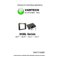
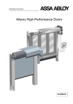
1
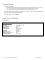
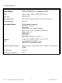
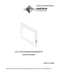
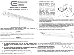
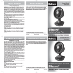
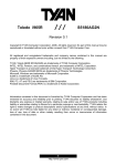
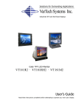
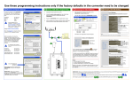
Solutions for Demanding Applications VARTECH S Y S T E M S I N C. 15.0” Class 1-Division 2 Compliant Panel Mount PC Model VTPC500PSS User’s Guide Read these instructions completely before attempting to operate your new Panel Mount PC Revision History Date 10/12/09 02/12/10 Rev No 00 01 Summary Page First Issue Added French Language 15.0” C1-D2 Compliant Panel Mount PC 2 486-0030-00-00 Safety Instructions PLEASE NOTE - This equipment is suitable for use in Class I, Division 2 or non-hazardous locations only. WARNING - EXPLOSION HAZARD - DO NOT DISCONNECT EQUIPMENT UNLESS POWER HAS BEEN SWITCHED OFF OR THE AREA IS KNOWN TO BE NON-HAZARDOUS. AVERTISSEMENT - RISQE D'EXPLOSION - AVANT DE DECONNECTER L'EQUIPMENT, COUPER LE COURANT OU S'ASSURER QUE L'EMPLACEMENT EST DESIGNE NON DANGEREUX. Read the Safety Instructions carefully and keep it for use later. The chassis metalwork of the module must be installed properly to the main earthing termination for Class 1 equipment. Care must be exercised in the application of the system to prevent overheating. Ensure that the ambient temperature around the system does not exceed 60°C and provide adequate means of ventilation to achieve this. When cleaning cut off the electrical supply at all times. Never use liquid or aerosol detergent, use a soft damp cloth instead. Never insert anything metallic into the chassis openings. This may create an electric shock hazard or hazard from rotating fan blades. To avoid electric shock, never touch the inside of the system. There are no user adjustable components inside, only a qualified technician should open the system’s case. Openings in the system enclosure are to allow for ventilation. To prevent overheating, these openings should not be blocked or covered. If the system does not operate normally – in particular, if there are any unusual sounds or smells coming from it – disconnect it immediately. Do not put pressure on the LCD panel screen because it is very fragile. Always handle the system with care when moving it. Take care that the system is disposed of correctly at the end of its life. If in doubt refer to your local ordinances or regulations for proper disposal. User to supply appropriate lockable type plug and power disconnecting switch. The end user must either supply a switch to their power outlet suitable for Class 1, Division 2 use (if adjacent to the power outlet), or locate the said switch outside the hazardous area. This equipment is suitable for use in a Class 1, Division 2, Groups A, B, C, and D or nonhazardous location only. 15.0” C1-D2 Compliant Panel Mount PC 3 486-0030-00-00 Explosion Hazard - Substitution of components may impair suitability for hazardous locations. Any Equipment or associated cabling connected to this device must be non-incendive and/or suitable for the Class 1, Division 2 area in which it is to be installed. Hazardous Locations: This equipment is suitable only for the locations specified on the product nameplate, specifically: Class I, Division 2 Groups A, B, C, D Non-hazardous locations The following statement applies to use in hazardous locations: WARNING! Explosion Hazard Substitution of components may impair suitability for hazardous locations. Do not disconnect equipment unless power has been switched off and area is known to be non-hazardous. Do not connect or disconnect components unless power has been switched off. All wiring must comply with N.E.C. articles 501-4(b), 502-4(b), 503-4(b) as appropriate. Peripheral equipment must be suitable for the location in which it is used. All hazardous-location equipment must be mounted in an enclosure that is suitably designed or rated for those specific environmental conditions that will be present, and designed to prevent personal injury resulting from accessibility to live parts. This equipment has an operating temperature code of T4 when operating in a 60`C (140`F) ambient environment. Do not install this product in environments where atmospheric gases have an ignition temperature of less than 135`C (275`F). 15.0” C1-D2 Compliant Panel Mount PC 4 486-0030-00-00 Environment and Enclosure Information: Review this information on enclosures before installing the product: ATTENTION: Environment and Enclosure This equipment is intended for use in a Pollution Class 2 industrial environment, in overvoltage Category II applications (as defined in IEC publication 60664-1), at altitudes up to 2000 meters (6561 feet). This equipment is supplied as open-type equipment. UL recognized and hazardous location equipment must be mounted in an enclosure that is suitably designed or rated for those specific environmental conditions that will be present, and designed to prevent personal injury resulting from accesibility to live parts. These units are shipped with a gasketed bezel to meet specified NEMA and IEC ratings if and only if mounted in a flat panel or enclosure with an equivalent rating. Peripheral equipment must be suitable for the location in which it is used. See NEMA Standards publication 250 and IEC publication 60529, as applicable, for explanations of the degrees of protection provided by different types of enclosures. The user may also reference the Industrial Automation Wiring and Grounding Guidelines, publication 1770-4.1, for additional installation requirements pertaining to this equipment. 15.0” C1-D2 Compliant Panel Mount PC 5 486-0030-00-00 Cleaning the LCD monitor To clean the LCD panel: Wipe the screen gently with a clean lens brush made of camel hair, or a soft, clean, lint free cloth. This is to remove dust and other particles without scratching the LCD panel. If it is still not clean, then wipe with a damp lint free cloth and blow on it to dry. Do not clean the panel with a keton-type material (e.g. acetone), or ethyl toluene, ethyl acid, methyl or chloride. These may damage the LCD panel. Do not apply pressure to the LCD panel. Standard Technical Specifications: LCD Monitor: STANDARD VERSION: Size / Type Native Resolution Contrast Ratio Viewing Angles Pixel Pitch Brightness (typical) Response Time (typical) Colors Supported: 15.0” XGA TFT LCD 1024 x 768 600:1 Horizontal: 140° Vertical: 120° 0.294mm 400 cd/m² 7ms 16.7 million 15.0” C1-D2 Compliant Panel Mount PC 6 486-0030-00-00 Computer System: Processor Intel Pentium Dual Core Processor T4500 2.30 GHz 800MHz FSB System Memory DDR2 533 DIMM 2 GB x 1 (expandable to 4GB) BIOS Phoenix-Award 16Mbit with RPL/PXE LAN Boot Hard Drive 320 GB SATA Operating System Microsoft XP Professional (SP3) for Embedded Systems Expansion Slots Dual PCI Back Panel I/O Ports PS/2 Keyboard Connector x 1 PS/2 Mouse Connector x 1 Power Inlet x 1 RS-232 Port x 3 (x1 422/485 Optional) USB 2.0 Port x 6 (x4 on Stainless Steel Models) RJ45 LAN Port x 2 VGA Port x 1 IEEE1394a x 2 Audio Jacks: Line Out x 1 / Line In x 1 Graphics LAN Integrated Intel GME965 GMCH Gen 4 Graphics Intel 82566DM 10/100/1000 (1st port) Intel 82573V 10/100/1000 (2nd port) DVD Drive (E-IDE / ATAPI) DVD-R, DVD+R, DVD-RW, DVD+RW, DVD-R DL, DVD+R9 CD-R, CD-RW, Touch Screen Resistive Touch Screen Interface USB 15.0” C1-D2 Compliant Panel Mount PC 7 486-0030-00-00 Power & Operational Specifications: Power Input 100 - 240 VAC 1.5A 50/60 Hz 12 - 24 VDC 6.0A max (optional); SELV source required if used Power Consumption 42W Temperature Operational: -32°F to 140°F Humidity Storage: -4°F to 149°F Operational: 20 to 40°C, 90% RH NC Storage: 0°C to 60°C -20°C to 65°C 5 to 65°C, 28% RH NC Installation of Your Panel PC Packaged with each carton will be: 1 – VTPC500PSS 1 - #10-32 Mounting Hardware 1 - Users Guide (Printed or on CD) 15.0” C1-D2 Compliant Panel Mount PC 8 486-0030-00-00 BEFORE MAKING ANY CONNECTIONS OR APPLYING POWER, FIRST READ THROUGH THE ENTIRE MANUAL Panel Mount Procedure Panel Mounting Procedure: 1- Cut and drill the panel (refer to the panel mount drawing, Figure A). Measurements are provided in inches and millimeters. Panel Mounting Cutout: 1- If access to the bottom of the enclosure is not available following installation, attach the power and all necessary cables to the bottom side of the enclosure at this time. 2- Install the enclosure in the prepared cutout. 3- Secure the enclosure using the lock nuts and washers, supplied with the unit, behind the holes running along the sides and the top and bottom of the cutout in the panel. Extra lock nuts and washers are provided. 4- Tighten all mounting hardware to a torque of 24 inch-pounds. ATTENTION: Mounting nuts must be tightened to a torque of 24 inch-pounds to provide a proper panel seal and avoid potential damage. Vartech Systems assumes no responsibility for water or chemical damage to the monitor or other equipment within the enclosure due to improper installation. NOTE: An easily accessible 15A fused or breaker protected outlet must be provided for installation of the unit. 5- Attach the power, video and system cables to the bottom side of the enclosure if you have not already done so. 15.0” C1-D2 Compliant Panel Mount PC 9 486-0030-00-00 Panel Mount Drawing: Detail –A– Connections to the Panel Mount PC Bottom Rear View (AC unit shown) - Connector Panel - 15.0” C1-D2 Compliant Panel Mount PC 10 486-0030-00-00 PLEASE NOTE – ANY EQUIPMENT OR ASSOCIATED CABLING CONNECTED TO THIS DEVICE MUST BE NON-INCENDIVE AND/OR SUITABLE FOR THE CLASS I DIVISION 2 AREA IN WHICH IT IS TO BE INSTALLED. Power Connection (Power In) AC models - The AC version of the Panel Mount PC includes an AC line cord which is 3ft long with stripped wires at the connection end. The user must supply a lockable industrial-type power supply plug to mate with their power outlet. Also, the end user must either supply a switch to their power outlet suitable for Class I, Division 2 use (if adjacent to the power outlet), or locate the said switch outside the hazardous area. DC models - The DC version of the Panel Mount PC has a lockable DC plug and socket supplied to which the user’s DC source must be connected. If the DC source (power brick or otherwise) is plugged into an AC socket within the hazardous area, the end user must supply a lockable industrial-type power supply plug to their power outlet. Also, the end user must either supply a switch to their power outlet suitable for Class I, Division 2 use (if adjacent to the power outlet), or locate the said switch outside the hazardous area. Serial Connections (COM 1-3) The Panel Mount PC is supplied with three serial connectors configured for RS-232. The connector is a 9 pin female connectors and can be set up for any baud rate from 300 to 19.2 baud. The connector is located on the bottom rear panel of the system. Ethernet Connections (LAN 1-2) The Panel Mount PC is supplied with two integrated Ethernet connectors. The interface will support 10/100/1000 BaseT connection to a local area network (LAN). The Panel Mount PC is supplied with two RJ-45 female connectors located on the bottom rear panel of the system. USB Connections (USB 1-4) The Panel Mount PC is supplied with four USB 2.0 connectors located on the bottom rear panel of the system. VGA Port The 15-pin female VGA connector can be used to connect to any analog VGA monitor. IEEE1394a (Firewire) The Panel PC is supplied with two IEEE1394a ports which feature high speed, high bandwidth which are hot pluggable to connect with IEEE1394 devices and peripherals. 15.0” C1-D2 Compliant Panel Mount PC 11 486-0030-00-00 Turning the system On and Off Before connecting the Panel Mount PC to power, connect any peripheral devices. As a general rule, any peripheral device should only be connected or disconnected when the Panel Mount PC is off with the exception of any USB or 1394 peripheral. The Panel Mount PC may be turned on using the main On-Off switch which controls the power outlet to which the unit is plugged in. Once the Panel Mount PC is turned on, the computer power reset switch must be depressed for Windows to start. Windows must be properly shut down before the main power switch is turned off to prevent the chance of corrupting files in the operating system. The Panel Mount PC is rated for continuous duty. However, to extend the life of the various components and conserve power, it is highly recommended that the system be properly shut down and power turned off when the Panel Mount PC is not in use. LCD Monitor Warm-up Time All LCD monitors need time to become thermally stable the first time you turn them on. Therefore, to achieve more accurate adjustments for parameters, allow the LCD monitor to warm (be on) for at least 20 minutes before making any screen adjustments. Maintenance The Panel Mount PC is designed to provide optimum service and performance with minimal maintenance including the occasional external cleaning. For cleaning the Panel Mount PC enclosure follow the suggested guidelines. General – NEVER use abrasive cleaners or solvent-based cleaners. Use a clean soft cloth. The Panel Mount PC should only be opened and serviced by a qualified technician. Keep the area around the Panel Mount PC clear and free of excessive dirt or other contaminants. Do not use water or any liquids on the Panel Mount PC. For Additional Assistance Contact Your VarTech Sales Representative Vartech Systems, Inc. 11529 Sun Belt Ct. Baton Rouge, LA 70809 800-223-8050 Fax: 225-297-2440 www.vartechsystems.com 15.0” C1-D2 Compliant Panel Mount PC 12 486-0030-00-00