1
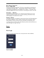
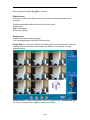
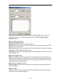
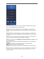
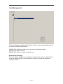
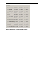
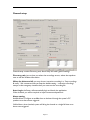
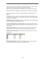
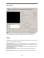
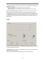
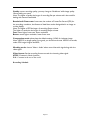
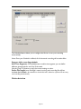
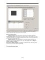
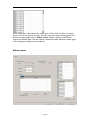
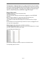
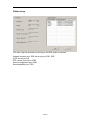
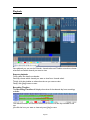
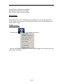
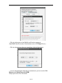
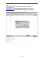
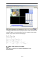
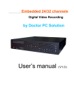
USER’S MANUAL
DIGITAL VIDEO
RECORDING SYSTEM
TechWell 6816 Series
Page 1
System requirements and Software installation
System requirements
Celeron D 2.66GHZ or higher
256MB System Memory or higher
ATI 64MB VGA Card or higher
Motherboard: Intel 915,945 or G series
Microsoft®Windows 2000/2003/XP/VISTA/WIN 7 Professional Operating system
Microsoft®Direct9.0
Software installation
a. Shutdown the computer, and plug the DVR card.
b. Install card driver.
As the picture above, click it will pop up a dialog
Then click [Install Driver] button, it will install card drivers automatically.
Note: when windows startup, it might pop up a warning – found new hardware, please
make sure click [cancel] button to cancel all windows auto-installation. Or DVR system
will fail because of the wrong drivers .
c. Restart operation system, and then run NVRec1600F.exe.
Software Introduction
Introduction
This DVR is real time video/audio monitoring and recording from multiple cameras. The
system supports up to 32 channels of video are simultaneously captured, compressed,
and recorded in real time. The corresponding 16 audio channels are captured,
compressed, and recorded as well. The system also includes a network client for
remote preview, recording, playback, and server management through the local area
network and Internet.
Basic Features
Page 2
·Server is capable of real time monitoring and recording of up to 32 video input
channels and up to 16 audio channels.
·Multiple record modes: manual, scheduled, or alarm event.
·Efficient file storage and network bandwidth utilization using advanced MPEG4/H.264
video compression technologies.
·Full featured remote network client capable of full remote administration, real-time
monitoring of and recording from multiple server systems.
·Local and remote playback of recorded video and audio files.
·Supports external alarm sensors and relays through an alarm control unit.
·Video recording and notification in the event of camera motion detection and/or
sensor inputs.
·Support for popular models of pan, tilt, and zoom (PTZ) cameras that can be operated
both locally and remotely.
·Support Mobile Monitoring.
·Support VNN(Virtual Native Network).
Page 3
Basic System Components
Server - NVRec1600F
The primary DVR Server Application. The Server is responsible for monitoring and
recording the video/audio inputs. It also provides a network service for real-time
video streaming and playback of recorded files over a network. The system can be
optionally equipped with an alarm controller for connecting alarm sensors and relays.
Web-Client - XNetPlay
The DVR Remote Client systems run on Windows Internet Explorer for remote
operation of the Server system, such as remote monitoring, remote Server state,
remote playback, and remote server control.
Playback - XPlayer
The Playback program is accessible from within both the Server and Client applications.
On the Server, Playback is used to review recordings made on the Server. On the
Client, Playback is used to connect to Servers and review recordings OR review
recordings made by the Client itself, locally. Playback provides many useful features to
make searching for the right video easy.
Server
First Login
There is one default administrative user in the system after a fresh installation:
Username: admin
Password: admin
Page 4
Enter the above and click [Log in] to continue.
Main Screen
The Server's main screen allows access to all of the commonly used features and
functions.
The following articles outline each area of the main screen:
Display area
Right control panel
Down control panel
Display Area
Display area shows monitoring images.
You may change display mode by the mouse action.
Single-Click on a channel to select it for further action; a thin red line will outline the
selected channel. Note that most functions only affect the red outlined, currently
selected channel.
Double-Click on a channel: Brings that channel to single full view. (Double-click again
to return to the previously configured multi-channel view.)
Page 5
Right-Click on any channel will show a multi-channel full view without any control
panels. (Right-click again to return to the previously view.)
Down control panel
Down control panel consists of Version Information, Function buttons, Information area,
Lock/Log off, Disk information, Exit.
Display mode: click the button, you may change display mode by mouse
selection.
System settings:
Click the button, you will see the menu below:
System settings contains most of the system configuration options. Please refer to the
System settings chapters.
Alarm output control is just for a test of alarm box.
Firstly, you must connect the alarm box correctly, and make sure it is on work(For
alarm box setting, please refer to Alarm sensor in System settings chapter).
Secondly, select the output port which you want to test, then click the [turn on] button.
If the alarm box is OK, its output LED will be on.
Preset position control allows you to program the PTZ camera to perform a series
of movements called a Tour. This system allows you to define a set of Presets, which
are numbered positions for the camera to point to. From there, you can program the
PTZ camera to go to a specified Preset in reaction to tour through the Presets in a
certain order.
Page 6
Firstly, make sure you may control the camera by using the PTZ camera control on
right control panel. (For camera setting, please refer to PTZ setting in System
settings chapter).
And then follow steps below:
Steps to Program Presets
Channel: Select the channel number to program.
Preset: Select a Preset number, and then use the PTZ camera control to aim the PTZ
Camera to a certain position.
Set Preset: Once the camera is pointed at the desired position, click [Set] to associate
that position with the selected Preset number.
Call Preset: If the Preset is already programmed, click [Call] to have the camera move
to that position now.
Steps to Program Tour
Add: Add the selected Preset to the Scan list. Set the Keep Time to have the Camera
stay at a certain location for a specified period of time. Note that the Keep Time must
include the time it takes the camera to move from the previous location to the desired
location, plus how long to stay there.
Save: Saves any changes to the Scan.
Scan Checkbox: Check this box at the top to start the Scan according to the list of
presets configured.
Photo browser
When you click this item, the system will show a dialog as below if you have snapshot
some photos by the [Snapshot] button:
Page 7
Steps to picture preview:
Choose D:\‘NVPhoto’ folder -> channel folder(such as ‘01’) -> bmp pictures.
Log management is a file that record System settings, Alarm information and so on.
Language select: there are two default choices: English and Chinese.
Playback
This button launches the Playback program. Please see the Playback chapter for
further details.
Snapshot
This button will take and store a snapshot of the current frame of the red highlighted,
currently selected channel. The snapshot image will be saved to D:\NVPhoto.
You can access the snapshots via the ‘[System settings] button -> Photo browser’.
Page 8
Information Area shows the Date, Time and current Server Uptime.
Lock
Click the [System Lock] button to lock the Server main screen, preventing further
user interaction until input username and password to login again.
Log off
Click the [Log off] button, and you will be required to enter a User and Password to
log in again.
Disk Information
It shows used and free disk space on the driver which is recording.
Exit
Click this button to exit the Server. You will be prompted to confirm the action.
Right control panel
Right control panel consists of Software Logo, Voice control, Channel control, PTZ
camera control.
Voice control
it is mute as default.
Click the loudhailer icon to turn on the voice.
Then go to ‘System settings - > Video settings -> Compress/Trans -> Working mode’
and select ‘Video + Audio’.
Page 9
Channel Control
The Channel Control bar has controls for 32 channels. The different option buttons
allow control of different features of each Channel.
Preview: Click on the numbered buttons to turn the different incoming channel
previews on and off. Click the [Open all] or [Close all] buttons to turn all cameras on
or off.
Record: Click on the numbered buttons to activate or deactivate recording for the
corresponding channel. Click the [Open all] or [Close all] buttons to turn all cameras
on or off.
NOTE: This is the manual Recording control. If Schedule is activated, you cannot activate or
deactivate recording. You will see the numbered buttons are disabled.
Color: The color panel has the Brightness, Contrast, Saturation, and Hue controls
for the channels show.
Select a channel on the left, and then adjust the different sliders so that the image is
most clear.
[Default] set all sliders to their default location for the selected channel.
[Same]: copy one channel’s settings to all others.
[Save]: save the changes. Or you will lose your configurations after reboot system.
Sensor: Click on the numbered buttons to activate or deactivate Alarm detection for
the corresponding channel. Click the [Open all] or [Close all] buttons to turn all
cameras on or off.
Page 10
NOTE: This is the manual Alarm control. If Schedule is activated, you cannot activate or
deactivate alarms. You will see the numbered buttons are disabled.
PTZ Camera Control
The PTZ Camera Control allows easy access to all PTZ Camera functions if you
configure the PTZ camera properly. (PTZ setting, please refer to ‘System settings ->
PTZ settings’.)
Zoom: The camera zooms in and out for tighter or wider view of the scene.
Focus: Adjusts the camera lens focus for the clearest image.
Iris: Opens and closes the camera iris, allowing more or less light into the lens.
Speed (green lights): Adjusts the speed of the directional movement in 5 ways.
Brush: Used to control auxiliary devices if so equipped, such as Light and Wiper.
Manual Control: The arrows in the PTZ ‘rosette’ allow manual control of the Pan and
Tilt movement of the camera, including diagonal movement.
Auto Control: Click on the center circular button to make the camera movement
automatically.
Setup
Setup contains User management, General setup, Video setup, Motion Detect, Alarm Sensor, PTZ
Camera and Others.
Buttons at the bottom are global for all Configurations:
[OK]: Saves changes and closes Local Setup.
[Cancel]: Closes Local Setup without saving any changes made since the last Save.
[Apply]: Applies changes without closing Local Setup. We recommend using this button often, every
time you move to a different Tab or Channel, to make sure that if you hit [Apply] you do not lose
changes you intended to keep.
Page 11
User Management
The User Management interface defines Users and their security authorization rights on
the Server and from Remote Clients.
[Modify]: Click Modify to change a user name and its authorization rights.
[Add]: Click to add a new user.
[Delete]: Click Delete to delete the selected user.
Authorization Settings
The authorization settings cover every feature of the product, down to which channels
a user can have access to for various functions. Check or uncheck the permissions
settings as needed.
Page 12
NOTE: Administrator account cannot be modified!
Page 13
General setup
General setup contains Directory path, Alarm setup and other general settings.
Directory path: just to show you where the recordings save to, where the snapshots
save to and the Website information.
When the drives are full: you may choose ‘overwrite recordings’ or ‘Stop recordings
& notify ’. We recommend that you keep the default setting – ‘overwrite recordings’,
except on the emergency situations that you must save the recording file.
Auto-Login: the Server will automatically login and launch the application.
When checked, you will be required to input username and password.
Alarm setting:
Audible Alarm: Configure an audible alarm to be heard through the system's PC
speakers once alarm event triggered.
Visible Alarm: when checked, system will bring the channel to a single full view once
alarm event triggered.
Page 14
Switch window when multi-channel alarm: when multi-channel alarm events occurred,
system will show the alarm channel to a single full view one by one.
Switch time: how long will the alarm channel show until next alarm channel coming.
Alarm output duration: Configure how long each Alarm event will last once triggered.
Alarm recording duration: Configure how long each Alarm recording will last once
triggered.
Output type: Alarm box output is a switch signal. When choose ‘High-voltage’, system
will output a ‘close’ signal. In the same way, system will send you a ‘open’ signal, when
your choice is ‘Low-voltage’.
Audible Alarm when no signal: Configure an audible alarm to be heard through the
system's PC speakers once video signal has lost.
Center has highest priority to alarm sensor: here center means Remote Client
System. When checked, client system will grab the control rights of alarm sensor from
Server System.
Switch automatically: when the numbers of shown channel is less than the total
channels, system will switch the shown channel automatically every switch time.
Enable Lock automatically: When checked, server system will turn to lock state
automatically.
Setup Storage Locations: Configure recording file storage locations on the local
hard drives. The Default only shows local drives other than C: .
Page 15
Video Profile
Note: In most of the video profile setting screens, you can use the [Copy To...]
button to copy the current Camera settings tab to other cameras. Use it carefully, as
you can easily replace one cameras settings with incorrect ones on accident.
Display
The Display screen shows you a current view of the Camera selected on the top, along
with several Camera configuration options.
Disposing OSD Text: The On-Screen Display text blocks can be moved anywhere on
the channel screen. Simply click on the camera name block or the date/time block and
set their coordinates to the desired locations.
Camera Name: You can enter a meaningful camera name, which will be shown on the
On-Screen Display (OSD).
Display Date and Time: If checked, you see the Server date/time on the OSD.
Preview mask: Enable you set a rectangle area to mask the screen display, but the
Page 16
recording will not do so. That means you also see a normal display without mask when
playback recording files.
X, Y: The coordinates of the top-left corner of the rectangle.
Width, Height: The coordinates of the bottom-right corner of the rectangle.
Alarm output channel when no signal: here ‘alarm output channel’ means alarm
box output port. So first of all, you have to connect alarm box to server system
correctly, and make sure alarm box is working good. (For alarm box setup, please refer
to ‘Alarm sensor’ chapter.) And then select output channel you desired. Now, once
the channel is no signal, system will send a switch signal to the output port which you
have selected.
Profile
The Video Profile settings allow you to configure the resolution, quality, and frame rate
for video recording on the Server.
Compression: just show you some information about local server compression, and
please keep the default settings.
Note: improper compression settings will make the recordings abnormal.
Page 17
Quality: means recording quality, you may change to ‘Excellence’ while image quality
cannot satisfy your need.
Note: The higher of quality the larger of recording files per minute and is also useful in
dealing with network bandwidth
Resolution & Frame rate: frame rate, the number of Frames Per Second (FPS) for
the recording; resolution, the fineness of detail that can be distinguished in an image on
a video display.
Note: The higher of FPS the larger of recording file per minute.
The higher of resolution the larger of recording file per minute.
Fast: means higher frame rate, lower resolution.
Better: means higher resolution, lower frame rate.
Compression mode: please keep the default settings ‘H.264’ for its better image.
Note: ‘MPEG4’, its image quality is not good, you should not choose ‘MPEG4’ to encode,
unless CPU usage is higher than 85%,.
Working mode: choose ‘Video + Audio’ when record the audio signal along with the
video signal.
Video format: Set the recording format to match the incoming video signal.
NTSC: Common in North America.
PAL: Common in the rest of the world.
Recording Schedule
Page 18
The Schedule feature allows you to configure the Server to carry out recording
automatically.
Note: Once your Schedule is defined, all of the manual recording will not take effect.
Steps to define recording schedule:
Add Time Segments: Click [Add] button to add a time segment; you can define
different time periods for each day of the week.
Use the [Copy To] button to copy the current settings to other.
Define File length: here ‘file length’ means how long each recording file will last.
Activate the Schedule: do remember to check this item; otherwise system will not carry
out recording automatically
Motion detection
Page 19
Once you set Motion detection, any motion on the entire channel screen will be
detected and notify user that an alarm event occurred.
Steps to motion detect:
Choose camera: select which camera you desire to set Motion Detection.
Create motion area: Click anywhere you want to detect in the channel screen and
you will see the pane turn to shadow. (Shadow means motion area.) Repeat elsewhere
on the screen to create other areas.
Define schedule: Click [Add] button to add a time segment, use [Copy to]
button to copy current day settings to other. (For detail, please refer to ‘Steps to
define recording schedule’)
Activate the alarm schedule: do remember to check this item; otherwise system
will not carry out motion detect automatically.
Corresponding output port:
Page 20
Here ‘output port’ means alarm box output port. So first of all, you have to connect
alarm box to server system correctly, and make sure alarm box is working good. (For
alarm box setup, please refer to ‘Alarm sensor’ chapter.) And then select alarm
output you desired. Now, once the motion is detected, system will send a switch signal
to the output port which you have selected.
Alarm sensor
Page 21
The Alarm Sensor configuration allows you to configure the Sensors that are attached
to the DVR Server. An I/O Alarm Box (purchased separately) is required for connecting
alarm sensors. A RS-232 to RS-485 converter may be needed to connect the alarm box
to the PC’s serial port (RS-232). The system can be configured to respond to sensor
inputs in a variety of ways (such as Audible alarm, trigger alarm output).
Steps to Alarm sensor:
Configure device: this is the most important step.
Type: type of alarm box.
Com port: Set which COM Port the Alarm Box is plugged into via the RS-232/485
converter.
Base chn: keep the defaults ‘8’, it means each alarm box has 8 input ports.
Total chn: means how many output ports the alarm box has.
(For example, one alarm box has 8 output ports; two alarm boxes have 16 output
ports)
As usual, please just choose the device type, select the com port you plugged into, and
then keep other settings default.
Choose sensor: select which sensor you desire to set alarm.
Corresponding output setup: here you may choose channel display alarm or output
port alarm response to the alarm sensor inputs.
Corresponding channel display alarm:
Just to click the channel you desired to response to the selected sensor.
Corresponding output port alarm:
Page 22
Just to click the alarm output you desired to response to the selected sensor.
Define schedule: Click [Add] button to add a time segment, use [Copy to] button to
copy current day settings to other. (For detail, please refer to ‘Steps to define
recording schedule’)
Activate the alarm schedule: do remember to check this item; otherwise system
will not carry out sensor alarm automatically.
PTZ setup
The PTZ configuration tab allows you to enter the configuration details for any PTZ
cameras connected to the Server. Be sure to reference your PTZ camera
manufacturer's documentation for the correct settings to enter here.
The Server supports the following PTZ camera protocols:
PELCO P series
PELCO D series
AB80 series
Panasonic series
I-node series
Philips series
Samsung series
YAAN series
ADR8060 series
If you have need for a specific protocol, please work with your sales representative to
discuss custom protocol programming.
COM Port: Select the COM port that the PTZ control is connected to.
PTZ Protocol: Select the correct protocol for use by this camera.
Baud Rate: Select the correct baud rate.
Address: Select the correct RS-485 address for the Camera.
Page 23
Other setup
The other setup tab describe you which port the DVR system is required.
Network transmit port: 5050 and its aux port 5051, 5052
HTTP service port: 80
PTZ remote control port: 6789
Remote configuration port: 5040
Remote playback port: 7050
Page 24
Playback
Start playback you can use the Calendar, channel select and Timeline controls to choose
what time and which channel you want to view.
Steps to playback:
Firstly, select the date from calendar.
Secondly, choose which channel you want to view from ‘channel select’.
Thirdly, click the timeline to select what time to you want to view.
Finally, click [play] button to start.
Recording Timeline
The Recording Timeline will display what times of the selected day have recordings
available:
The channel numbers are listed on the left, and the hours of the day are listed on the
top.
Just click the hour you want to view and press [play] to start.
Page 25
Green Timeline: means Auto recordings.
Red Timeline: means alarm recordings.
Blue Timeline: means manual recordings.
Web-Client
Web-Client system runs on Windows Internet Explorer for remote operation of the
Server system, such as remote monitoring, remote Server state, remote playback, and
remote server control.
DNNS setting
·Click the button
, you will see the menu below:
·click the VNN/DNNS configuration,and then click the register new account button,you
will see the menu below:
Page 26
·Fill in the information of the DNNS userID and the password
(Tips:DNNS UserID must be a E-mail address such as [email protected] )
·Fill in the domain name that you wanted,then click the Next button.
·you can own the domain name that you wanted,now ,you can use the VNN.
Steps to use Web-Client with VNN
Firstly, input server IP on IE browser.
Page 27
Note:
If you visit server system in LAN, please input IP directly (For example:
http://192.168.0.100).
If you visit server system through INTERNET, please input our server name
http://www.nvdvr.net or your DNS name. (For instance: http://nvrec.nvdvr.net).
Secondly, download and install ActiveX controls – ‘XWebplay.cab’ from server system.
Thirdly, login.
Domain name:147288.nvdvr.net
Port: 5050
Username: 1
Password: 1
Fourthly, double-click camera icon for remote monitoring.
Page 28
Double-click the camera icon which you want to view.
[Start]: means receive all camera images.
[Stop]: means stop receive image.
[Windows select]: here you may choose 1, 4, 9, 16 channels to view the images from
sever system.
Tips:
Double-click on the channel: Brings that channel to single full view. (Double-click again
to return to the previously view.)
Right-click on the channel image, you may stop the video by pop-up menu.
Fifthly, remote playback
Page 29
Click ‘Remote playback’, you may choose what time (date & time) and which channel,
recording type you want to view, then press [Search] button on the right control panel.
The system will pop up a file list according to your search condition. Double click the
listed file and you will see the remote recording image.
Mobile Monitoring
Access to mobile client
1.Instruction for Android__ monitor.
You can see the folder named “Android OS”
2. Instruction for iPhone__ monitor
You can see the folder named “Iphone imobileplayer”
3. Instruction for Symbian, Mobile and other OS__ monitor
You can see the folder named “Symbian and mobile OS”.
As Symbian, Mobile and other OS for example:
Method Ⅰ
Open the CD of this DVR Card . Clip the file XMobilePlay, and choose
XMobilePlay_En.jar.
Page 30
CD Root of DVR Card
Clients for mobile
Method Ⅱ
Download the software with your mobile. Input the site as follows: :
http://www.nvdvr.net/en.jar(English Version)
Demo based on normal mobile phone(MTK Platform)
Install mobile client
1,Download client from your mobile.
Input http://www.nvdvr.net/en.jar in Browser
2.Find the JAR file in your mobile(The client copied from CD named
XMobiePlay_EN.jar )
3.Install the client.
4.After the successful installation of client, we must Log in
our router to deploy NAT of the server(we suggest to use the HTTP service port of
8080)
5. Run this client.
Input your registered domain and port. You also can run our DEMO domain.
Page 31
Parameters of Demo
Server address:nv930x.nvdvr.net
Input port: 8081 (Can be user-defined, it is recommended to use 8080 or bigger than
8080)
User Name: 1 (This is the DVR server login user name)
Password: 1 (This is the DVR server login password)
Note: The above username and password are not the ones you registered the domain;
they are the ones you login the DVR sever
Page 32