1
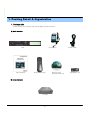
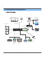
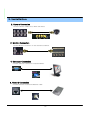
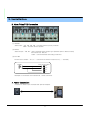
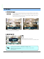
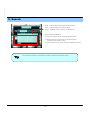
4 CH MPEG4 DVR
USER'S MANUAL
(VERSION 3.7.37.27)
This symbol is intended to alert the user to the presence of unprotected
“Dangerous voltage" within the product's enclosure that may be strong
enough to cause a risk of electric shock.
This symbol is intended to alert the user to the presence of important
operating and maintenance (servicing) instructions in the literature
accompanying the appliance.
WARNING
TO REDUCE THE RISK OF FIRE OR ELECTRIC SHOCK, DO NOT EXPOSE
THIS APPLIANCE TO RAIN OR MOISTURE.
NOTE: This equipment has been tested and found to comply with the limits for a class digital device,
pursuant to part 15 of the FCC Rules. These limits are designed to provide reasonable protection
against harmful interference when the equipment is operated in a commercial environment.
This equipment generates, uses, and can radiate radio frequency energy and, if not installed and
used in accordance with the instruction manual, may cause harmful interference to radio
communications. Operation of this equipment in a residential area is likely to cause harmful
interference in which case the user will be required to correct the interference at his own expense.
Disposal of Old Electrical & Electronic Equipment (Applicable in the European Union and other
European countries with separate collection systems).
This symbol on the product or on its packaging indicates that this product shall not be treated as
household waste. Instead it shall be handed over to the applicable collection point for the recycling
of electrical and electronic equipment. By ensuring this product is disposed of correctly, you will
help prevent potential negative consequences for the environment and human health, which could
otherwise be caused by inappropriate waste handling of this product. The recycling of materials will
help to conserve natural resources. For more detailed information about recycling of this product,
please contact your local city office , your household waste disposal service or the shop where you
purchased the product.
VER.: 1.0, P/N: 040147
PRECAUTION
All the safety and operating instructions must be read before the unit is operated.
• Make sure to switch the power off before you install the DVR.
• There is the danger of an electric shock if the DVR is opened by an unqualified service engineer or installer.
• Avoid using the DVR outside of the reference temperature and humidity indicated in the specification.
• Avoid exposing the DVR to violent movement or vibration.
• Do not use or store the DVR in direct sunlight or near to any source of heat.
• Do not place any object into the holes used for air circulation.
• Always use the DVR in a well ventilated location to prevent overheating.
• Risk of explosion if battery is replaced by an incorrect type.
• Dispose of used batteries according to the instructions.
• When the system is overheated, the below warning message will be displayed
at the monitor.
“ SYSTEM IS OVERHEATED, TURN THE POWER OFF AND CHECK COOLING FAN”
In this case, do the power off right away and check the cooling fan working.
• INDEX
• CHAPTER 1. Packing Detail & System organization
1. Product Contents List -------------------------------------------------------- 6
2. System Organization --------------------------------------------------------- 7
• CHAPTER 2. Description
1. Front Panel --------------------------------------------------------------- 8
2. Rear Panel --------------------------------------------------------------- 10
3. Remote Controller ---------------------------------------------------------- 11
• CHAPTER 3. Installation
1. Hard Disk Installation ------------------------------------------------------- 12
2. CD-RW & Hard Disk Installation ----------------------------------------------- 14
3. Camera Connection -------------------------------------------------------- 16
4. Monitor Connection -------------------------------------------------------- 16
5. Computer Connection ------------------------------------------------------- 16
6. Network Connection -------------------------------------------------------- 16
7. Alarm/Relay/PTZ Connection ------------------------------------------------- 17
8. Power Connection --------------------------------------------------------- 17
9. Finishing Installation -------------------------------------------------------- 18
※ Hard Disk Format ---------------------------------------------------------- 18
• CHAPTER 4. Display
1. System Power ON ---------------------------------------------------------- 19
2. Screen View Selection ------------------------------------------------------ 20
3. Screen Rotation Mode (SCR MODE) -------------------------------------------- 20
4. PTZ/FOCUS Control -------------------------------------------------------- 21
5. System Power OFF --------------------------------------------------------- 21
• CHAPTER 5. Search
⊙ Go to Search Mode --------------------------------------------------------- 22
1. Search by Date/Time ------------------------------------------------------- 22
2. Search by Event ----------------------------------------------------------- 23
• INDEX
• CHAPTER 6. MENU
⊙ Go to Menu -------------------------------------------------------------- 25
⊙ Go to System Setup -------------------------------------------------------- 25
1. Display --------------------------------------------------------------- 26
2. Camera -------------------------------------------------------------- 27
3. Audio ----------------------------------------------------------------- 30
4. System --------------------------------------------------------------- 30
5. Event/Sensor ---------------------------------------------------------- 36
6. Disk Management -------------------------------------------------------- 39
⊙ Go to Record Menu -------------------------------------------------------- 40
1. Recording Operation ------------------------------------------------------ 40
2. Continuous/Motion Record Schedule ----------------------------------------- 41
3. Alarm Record Schedule --------------------------------------------------- 42
⊙ Go to Archiving ----------------------------------------------------------- 43
1. CD-RW and USB Back up ------------------------------------------------- 43
• CHAPTER 7. CLIENT
⊙ Remote Program Install ----------------------------------------------------- 44
1. Function Introduction ----------------------------------------------------- 46
2. Setting ---------------------------------------------------------------- 47
3. Monitoring ------------------------------------------------------------- 54
4. Search ---------------------------------------------------------------- 58
5. Web Client ----------------------------------------------------------- 65
• CHAPTER 8. SPECIFICATION
1. Specification ------ ----------------------------------------------------- 66
1. Packing Detail & Organization
1. Package List
Please confirm the contents after the package has been opened.
① Basic Contents
DVR
User’s Manual
12V Adaptor
Remote Controller
② Option Contents
CD-RW
6
Remote Client
Program Install CD
Power Cable
AAA Battery X 2
1. Packing Detail & Organization
2. System Organization
Alarm Sensor #1-4
Camera #1-4
Image Printer
Remote Client PC
Relay Out
Alarm Input/Out
NETWORK
AVI Backup
TCP/IP
Video In
WEB Client
Video Out
Backup
Remote
Controller
USB
VCR
VGA
Monitor
CD-RW
AV Monitor
7
2. Description
1. Front Panel
①
④
②
⑤ ⑥ ⑦ ⑧ ⑨ ⑩
③
⑪
⑫
① Power : System Power On/Off
② Channel Select button : Select Channel or Input Password.
③ Led indicator : Indicate Present System Status information (POWER: System On/Off ,
RECORD: Record On/Off , NETWORK: Client Network Connection Status
ALARM: Alarm Sensor Detection Status)
④ USB PORT: USB port for use the USB memory stick and USB HDD Backup
⑤ MENU : Go to System Menu.
⑥ SEARCH : Go to Search Mode for Searching Recorded Data.
⑦ SPLIT : Select Screen Division Mode or Rotation Mode.
⑧ PTZ/FOCUS : Go to Camera PTZ/FOCUS Control.
⑨ EXIT : Cancel Setup or Return Previous Mode.
⑩ ENTER : Apply Changing Setup.
⑪ Search Controller : Searching Recorded Data or Control menu & PTZ/FOCUS.
⑫ Remote Controller Sensor Input.
• Power button (Soft key function) is designed to prevent system failure, due to
wrong operation.
Tip
• Channel selection button is prior to SPLIT.
• When remote controller sensor input is blocked by something, it cause
1 remote controller do NOT work properly.
• Press any Button and it will be followed by a beep sound.
8
2. Description
1-1. Front Panel
①
⑥
②
③
⑦ ⑧ ⑨ ⑩ ⑪ ⑫
④
⑤
⑬
①
②
③
④
Power : System Power On/Off.
⑧
⑨
⑩
⑪
⑫
⑬
SEARCH : Go to Search Mode for Searching Data.
Channel Selection Button : Select Channel or Input Password.
Search Controller : Searching Recorded Data or Control Menu & PTZ/FOCUS.
Led Indicator : Indicate Present System Status Information.
( POWER: System On/Off , RECORD: Record On/Off , NETWORK: Client Network Connection
Status, ALARM: Alarm Sensor Detection Status )
⑤ CD-RW : CD-RW Device for Backup.
⑥ USB Port: USB port for use the USB memory stick and USB HDD Backup
⑦ MENU : Go to System Menu.
SPLIT : Select Screen Division Mode or Rotation Mode.
PTZ/FOCUS : Go to Camera PTZ/FOCUS Control.
EXIT : Cancel Setup or Return to Previous Mode.
ENTER : Apply Changing Setup.
Remote Controller Sensor Input.
• Power button (Soft key function) is designed to prevent system failure, due to
wrong operation.
Tip
• Channel selection button is prior to SPLIT.
• When remote controller sensor input is blocked by something, it cause
1 remote controller do NOT work properly.
• Press any Button and it will be followed by a beep sound.
• In case of CD-RW, the real appearance will be differ from the above picture
1 depends on its model.
9
2. Description
2. Rear Panel
①
②
④
⑤ ⑥ ⑦ ⑧ ⑨
③
⑩
① Video In : BNC Port for Connection of DVR & Camera. (4 Camera Connectable)
② Monitor Out : Output DVR Video to AV Monitor.
③ Alarm/Relay/RS-485 : Connect Port for Sensor, Relay, & PTZ.
④ Loop Back : Output DVR Camera Video to Loop Back Port. (4 BNC Port)
⑤ Spot Out : Output Spot-out Video to AV Monitor.
⑥ NTSC/PAL : Select NTSC or PAL Type.
⑦ S-Video : Output Video by Connected SVIDEO.
⑧ Audio Out : Output Audio Data.
⑨ Audio In : Audio Input Terminal Related with #1~4 Camera.
⑩ Ethernet (TCP/IP) : Port for Cross cable. (Possible to Remote Surveillance.)
⑪ RS-232C : Connect Port for Program Debug.
⑫ DC Power Input : Power Supply by DC 12V Adaptor.
Tip
• It is important to use the specified power adaptor.
10
⑪ ⑫
2. Description
3. Remote Controller
POWER:
MENU: Open Menu
System
ON/OFF
Channel Selection Button
(4ch Available, #1~4 Button)
EXIT:
Cancel Setup
or Return to
Previous
ENTER: Apply Setup Change
Search Controller : Control Playback Option,
Menu Movement, PTZ/Focus Control
Change
Screen Mode
Open
Search Mode
PTZ/IRIS Mode
• Unused Button’s Description is Omitted.
• Every Button is Operated Same as Front Panel Button.
• Remote Controller can Operate when Remote Controller Sensor Input Part Reacted Each Other.
※ If there are many DVR at the same place, they are reacted together when press remote controller.
11
3. Installation
1. Hard Disk Installation
(1) Jumper Setup as Master or Slave
• Jumper Setup as master or Slave, Following the
` Direction of Surface of Hard Disk.
• Jumper Located at Hard Disk Data Cable or
1 Rear Side of Hard Disk.
• If One Hard Disk Installation, Setup as Master
If Two Hard Disk Installation, Second One Setup as
Slave.
“When Hard Disk Add or Exchange, Must System Off
Properly (System Off by Power Button). If not, it’s a
Cause of Fatal Hard Disk Error.”
※ Example of Samsung HDD Jumper Setup
• Refer to General Pin Setting in Jumper Pin Setting on HDD Surface.
• When One HDD Install, Setup Pin as Master and Connect Pin
1 at the Left End of Jumper.
• When Two HDD Install or Additional Install, First One Setup as
1 Master and the Other is for Slave. Slave Setup has No Pin.
• When More than Two HDD install, Setup as Master or Slave
1 to Connect One IDE Cable at the Same Method of Above.
“Please Use Hard Disk which Possible to Supply Higher than
UDMA66!”
(2) IDE Cable Connection to Main Board
• Confirm the IDE Cable Inside of Product
• Among the Three Connector, Indicated Blue Color
1 Connector Must be Connected with Main Board.
Other 1 Connectors Connected with HDD
12
3. Installation
(3) Connect IDE Cable to Hard Disk
• Insert Disk, Red Cable Head to Power Cable Plug
• Connect Power Cable to Hard Disk in the Same Way
※ If One HDD Install, Connect with End of Connector (Black)
Recommended.
If Add HDD, Connect with Middle Connector (Gray)
Recommended.
Two HDD Installation
Third HDD Installation
Bracket Installation
(4) After Finishing Cable Connection, Attach Hard Disk with Screw & Bracket
Tip
IDE2
IDE1
• When installing master HDD, please connect
to IDE1 Port (master cable).
• When 2 HDD are used, set the jumper of one
HDD to master and the other to the slave.
• IDE hard disk port can be connected by two
devices using one cable (port). To prevent
confusing, the device are named “Master” &
“Slave”. “Master” is one hard disk or the first
hard disk and ‘Slave’ is below second hard disk.
• Please remove the power adaptor before you
remove, add, or change the HDD.
13
3. Installation
1. CD-RW & Hard Disk Installation
(1) Jumper Setup as Master or Slave
• Jumper Setup as Master or Slave (Refer to CD-RW
1 Direction at the Surface).
• If Install One CD-RW at One IDE Cable, Setup as Master
If Install One CD-RW & HDD at One IDE Cable,
1CD-RW Setup as Slave.
“When CD-RW Install, Exchange, or Remove, Please
System Off Properly (System Off by Power Button)
and Disconnect DVR Power.”
14
3. Installation
(2) Connect by IDE Cable & Power Cable at the CD-RW
Tip
For Rear Panel
IDE2
IDE1
• When install master HDD, please connect
1 to IDE1 Port by cable.
• It means that the jumper of the HDD must
be set to master selection.
(3) After Assemble with HDD Bracket & Connect Cable (Refer to Previous page for HDD Setup)
<EX>When Two HDD Installation
(4) Example of Install CD RW & HDD
HDDx2+CDRW
HDDx3
15
3. Installation
2. Camera Connection
Connect Camera at BNC Port in Back Side Panel.
3. Monitor Connection
Connect Monitor Terminal or S-VHS Terminal to Monitor
4. Computer Connection
Connect VGA OUT Terminal to Computer Monitor
5. Network Connection
Connect Ethernet Terminal and Network Cable
16
3. Installation
6. Alarm/Relay/PTZ Connection
①
②
③
(1) ALARM
Alarm Input - ‘IN1, IN2, IN3, IN4’ : Connect Sensor Input by Channel
‘GND’ : Connect Ground System
(2) RELAY
Alarm Output – ‘NO, NC’ : After Checking Alarm Output Type (Normal Open or Normal Close)
and Connect to ‘NO, NC’
‘COM’ : Connect Remain Grounding Conductor
(3) RS-485
Connect PTZ Camera – ‘D+, D-’ : Connect PTZ Camera Control Line (+ , – Terminal)
RS485
D+
D-
PTZ 14 Pin Cable
⑨ R+
⑩ R⑪ T+
⑫ T-
Example of Connection PTZ Camera No. 14 Pin Connector
7. Power Connection
Connect DC Power Input Terminal and Specific Adaptor
17
3. Installation
8. Finishing Installation
System Start by Power Button after Finishing Installation
※ Hard Disk Format
- When the new HDD has not been formatted, system will not be able to recognize the HDD.
Therefore, the situation will be the same as when no HDD has been installed (Only display
possible, not work menu & search). Please format the HDD when a new HDD has been installed.
1. Power On
2. New HDD Format
(Select By Play , Backward Play Key)
When new discovery HDD are two, It ask about each
format. Then choose the Yes about all HDD. If you
Format the first HDD only, maybe second HDD don’t
Format.
※ When you are currently formatting the HDD. Do not turn
off! If turned off, fatal error may occur.
3. System Start (Initial Mode)
18
4. Display
1. System Power ON
• Press Power Button to Start System
• After Checking Hard Disk, Need input Password to
1 Operation
• Initial Screen View Mode is Quad Division Mode
1 and Recording Mode
CAMERA
2005/01/01
00:00:00
Picture for Power On
after Finishing Installation
• Each Channel Indicate Camera Name & Recording Status
• Present Time & Date Indicate at Monitor Central Lower Side
• Check System Condition at LED
Tip
POWER : Showing System On/Off
RECORD : Showing Record On/Off
NETWORK : Showing Client Connection Status
ALARM : Lighting when Sensor Alarm Activate
19
4. Display
When connected by the Remote Agent or Web Client,
Indicator appears.
• Network condition as indicated below:
Blue: Network is stable.
Green: Network is unstable.
Red: Network is very unstable.
2. Screen View Selection
• Select One Channel among 4 Channels
• Move to One Enlargement Watch Mode when Quad Screen Division Mode
• Move to One Enlargement Watch Mode when Rotation Mode
3. Screen Rotation Mode (SPLIT)
SPLIT
• User can Select 3 Kinds Watch Mode
① Quad (4CH) Division Watch Mode
② Selected 1CH Watch Mode
③ 4CH Rotation Watch Mode
• Quad (4CH) Watch Mode is Initial Mode when System Start
Quad (4CH) Division
Watch Mode
Selected 1CH
Watch Mode
20
4CH Rotation Mode
4. Display
4. PTZ/FOCUS Control
PTZ/FOCUS
• Control Camera PTZ (Pan/Tilt/Zoom) & Focus (Only Useable for Proper Camera)
• Press PTZ/FOCUS Button to Open PTZ Menu at Right-Under Side and Control by
1 Search Controller
• Press PTZ/FOCUS Button Second Time to Open PRESET, SWING .FOCUS, IRIS
Menu and Control by Search Controller
• Each icon mean the button of front keyboard.
• Control each function by front keyboard.
• F: Focus
I: IRIS
5. System Power Off
• Press Power Button to System Off
• Input Password and Press Enter to Shutdown System
Tip
• System Log-On Possible ID : ‘Administrator’, ‘Manager’, ‘User’
Administrator: All Function Access (System On, Shutdown, Setup, Search)
Manager: System On and Search
User: System On
21
5. Search
⊙ Go to Search Mode
SEARCH
• Press Search Button and Log-In
Administrator or Manager
• Use Direction Key to Move Menu
ENTER
• To Open Each Menu Press
Enter or Press Play Button
EXIT
• Return to Previous.
(Move to Previous Menu or Exit Search
1 Mode and Return to Watch Mode)
1. Search by Date/Time
- Possible to Search Recorded Date & Time
① Move Cursor to Selected Date in Calendar
(Recorded Date & Time Indicated by Gray Color)
② Press Enter to Open Selected Date
③ Recorded Time Appear to Under Side
④ Press Enter at Selected Time
(One Scale is 15 Minutes)
⑤ Menu Disappear and Output Recorded Video
• Showing Recorded Date & Time at Left-Upper Side
1 as Watch Mode.
1 Showing Playing Condition at Right-Under Side.
• Channel Selection Button in Watch Mode & SPLIT
Button are Apply the Same as Search Mode. 1
(But Menu, Search, and PTZ/Focus Buttons are Exception)
2004/01/01
00:00:00
22
>
5. Search
• Control Playing Video
①
: Basic Playing Mode (Normal Speed (1X) Forward Playing)
②
: Normal Speed Backward Playing
③
: Pause Video
④
: Fast Forward (2 ~ 64 Speed)
⑤
: Fast Backward (2 ~ 64 Speed)
⑥
: Same Function as # ④,⑤
※ Press Normal Forward/Backward Button in Pause, Move to Next/Previous Frame.
2. Search by Event
- Searching Video with Event Occurrence to Set up Period
Set up Period to Select Start Date & Finish Date
for Searching Event
Alarm : Searching Alarm Event during the Selected
1
Period
Motion : Searching Motion Detected Event during
1
the Selected period .
Timer : Searching Schedule Change or Recording
1
Setup Change Event
System : Searching Power On/Off Event (etc.)
1
Concerned System Event
Event List Showing at Below Output Window
Channel: Choose the channel for searching.
• Alarm, Motion, System can be Select plural by Check (V)-(ENTER)
Tip
• To Change Setup, Press Enter and Press Direction Key
After Changing Setup, Press Enter to Exit.
23
5. Search
• Date : Indicate Event Occurrence Order & Date
Time : Indicate Event Occurrence Time
Event : Indicate Event Contents & Camera No.
• Event Searching Method
① User can Search Event Using by Direction key
② Search Event to Press Enter at Selected Event
from Event Occurrence Time
③ Control Video is the same way as Time Mode Control
Tip
• The Search by Event is not Base on Video, but Event Occurrence Time.
24
6. Menu
⊙ Go to Menu
① Press Menu Button on Front Panel in Watch Mode
② Ask Password
③ Input Password Using by Channel Select Button
1 ([1][2][3][4])
④ After Input Password Press Enter to See Menu
• Initial administrator, manager, user password is 1234.
Tip
• Showing password as *
• Changing password (System setup->System -> User management )
• Only watch mode can enter setup.
(Search & PTZ/Focus mode can’t move to Menu)
⊙ Go to System setup
• Choose the “ setup”
25
6. Menu
1.Display
- Video Setup for Watch Mode
• Every System Setup can Change or Maintain
1 at Menu (6 Setup)
Move to Menu Using by Up
& Down Button
•
ENTER
•
To Open Detail Menu, press “the Enter”
•
EXIT
Return to Previous Menu or Return to Watch Mode.
1-1. OSD
• Status Bar : Record Condition Mark On/Off
(Recording: Red, Pre-recording : Green)
• Camera Title: Setup Camera Name to Show Left-Upper
Side
• Event Icon: Indicate the menu location by icon
• Border : Border Mark On/Off when 4CH Division Watch
Mode
• Border Color : Select Border Color
(White, Blue, Red, Yellow, Green, Gray)
• Alpha Blending: Choose the transparency(1~100)
1-2. MONITOR
• Sequence Dwell : Setup Rotation Cycle Time
(1~60 Sec.) when 4CH Rotation Mode at Watch Mode
• Spot-Out Dwell : Setup Spot-Out Time Cycle
(1~60 Sec.) to Transmit Video
• De-interlace Mode : Remove Screen Spread on High
Resolution , Low Frame
※Only Applying When D1(704X480)
• Alarm Pop-Up Mode: When alarm happen, Alarm happened
channel Pop-up
• Alarm Pop-Up Dwell: Alarm Pop-up Time(1~60Sec.)
Tip
• After changing the setup data, press the
26
button.
6. Menu
2.Camera
- Setup Camera
2-1. Camera Title
• Covert : Setup Covert On/Off
*What’s Covert?
When Covert On Watch Mode, Display Video is Hidden, but Recording is On.
• Title : Setup Camera Name by Virtual keyboard
• Input the title by “Enter” after
choose by button.
2-2. Color Setup
• Control the Monitor Bright, Contrast, Color, Tint
• All Setup Possible to Control 0~100
• Setup Channel by Channel
27
6. Menu
※ How to use the Virtual Keyboard
Tip
• Input the title by “Enter” after choose by
• Press the
button for shift then choose the other characters.
2-3. PTZ Setup
• PTZ Address : Select PTZ Camera Address
• Enter button and setup the detailed PTZ
• Baud Rate : Setup PTZ Communication Speed
(2400, 4800, 9600,19200, 38400 BPS)
• PTZ Protocol : Select Kind of PTZ Camera
※PTZ Supplied Protocol : Samsung(MRX-1000), Samsung(SCC641),Honeywell(SD1)
Honeywell (GMC),Lilin(Fastdome), Fastrax(Ⅱ), GC(655N),
D-MAX, Sunin DSC-230, Scan Dome-Ⅱ, Vicon,Philips8560-700
Sensormatic,Panasonic(WV-CS850), Panasonic(WV-CSR604),VRX-2101
Kalatel(KTD-312), PELCO-D, PELCO-P,Dynacolor(D7722)
28
6. Menu
2-4. Motion Sersor
• Choose the Partial Motion Region channel by
channel
• Sensitivity: 1~10
• Move Cursor by Direction Key and Press Enter at
Selected Region
•
•
•
•
Select All : Select Entire Region
Deselect All : Cancel Region Setup
Cancel : Cancel Change Setup & Exit
Save & Exit : Save the Changes & Exit
29
6. Menu
3. Audio
- Audio Setup
• Live Audio : Audio Output ON/OFF
Live Audio Output from Audio In Terminal
• Audio Monitoring Channel: Select Channel for Audio Output
1
Nr. 1~4 Audio In
• Network Audio TX: Choose the Audio transmission
• Network Audio RX: Choose the Audio receive
• Keypad Buzzer : Keypad Buzzer ON/OFF
•Remote Control : Remote Buzzer ON/OFF
4. System
- Basic Environment Setup
4-1. date/time
30
6. Menu
※ First of all, Time zone should be setup as your location.
• Date TIME: Setup Present Date
(If Time Setup to Past Date, Ask Delete Data for the Past Date.
NO->Date/Time No Change, YES->After Delete Past Data and Change Date/Time )
• Date Format : Select Date Output Type (Ex: 2005-00-00, 2005/00/00)
• Time Format : Setup Time Type as 12 Hour Base or 24 Hour Base
• Network Time Server: Setup Present Time by Time Server.
• D.S.T: Daylight Saving Function On/Off
• Time Zone: Choose the time by GMT standard.
Tip
※ How to setup Time
1. Setup the time zone according to your location.
2. Setup the network time server and press the “Sync” button.
3. When the date/time is unable to be produced automatically, setup the date/time manually.
4. When the above steps are not followed, time and recording data search error may occur.
31
6. Menu
4-2. Network
•
•
•
•
•
IP Address : Input IP Address
Gateway : Input Gateway IP for Internet Server
Subnet Mask : Input Subnet Mask IP
DNS Server: Input DNS Server IP
Network Speed : Setup Network Speed
(Network Speed from System, Depend on Network Status)
※ If the network setup has been changed, new changes will
be enabled, after rebooting.
• DHCP (Dynamic Host Configuration Protocol) : Indicate IP Address for the DVR Automatically.
1.
2.
3.
4.
5.
Enter to ‘System -> Network’ on the Menu.
Setup DHCP On/Off.
DHCP Off : User Input IP Address by Himself.
DHCP On : After DHCP On, Reboot the System.
Can see the setup IP automatically at the system information.
• DDNS (Dynamic DNS): You can connect the DVR by the fixed domain name(ex.00115f000001.dvrlink.net) at
client or Web without entering the IP address.
※ If you use the DDNS, there is no necessity to enter again the IP Address every connection.
1.
2.
3.
4.
5.
6.
Enter to ‘System -> Network' on the menu.
Setup DHCP On or Enter the IP address.
Setup DDNS ON and reboot.
Enter to ‘System -> System information’ on the menu.
Confirm the MAC address.
The domain name is "MAC address.dvrlink.net".
EX) If Mac Address is 00-11-5f-00-b5-a7, the domain name is "00115f00b5a7.dvrlink.net"
7. If you connect by "00115f00b5a7.dvrlink.net" at client program or Web, you can connect the DVR.
Tip
※ 1. If your network connected to the router, please port forwarding.
2. Please enter the exact IP address, DNS Server, Gateway, and Subnet Mask.
3. Please connect the DVR to the External Network.
If you do not follow step 1,2,and 3 , you will not receive the DDNS service.
32
6. Menu
4-3. Mail
•
•
•
•
Server: Setup the mail server
• Setup by Virtual Keyboard after press the “ENTER”
Port: mail server port
Security: On/Off
User & Password: input the DVR login user ID and Password.
33
6. Menu
4-4. User Management
User setup
• It is consisted 3 User Group as Administrator,
Manager, User.
• Total 7 user belong to 3 User Group can be made.
•
•
•
•
•
Input User ID, Password.
Choose the Group.
Input the E-mail Address.
It can edit User ID information.
E-mail notification On/Off : 1. ON:
2. OFF:
• Input the E-mail by Virtual Keyboard.
34
6. Menu
4-5. System Information
• S/W Version: Server Firmware Version
• Video Signal Type: NTSC or PAL
• Disk Capacity: used HDD capacity of the total HDD
capacity.
• IP Address: DVR’s IP Address
• MAC Address: Fixed MAC address of the DVR
35
6. Menu
4-6. Factory Default
• Press “Press” to Start Initialize.
• Showing Warning Message and Press OK to Run Initialize.
• If do Factory Default, Every Setup is Initialized, but Saving Image is Not Erase.
5. Sensor
5-1. HDD Event
•
•
•
•
•
36
Drive: HDD connected location
Threshold: Alarm setup temperature
Value: HDD Temperature
Smart Alarm: On/Off
Check interval: HDD checking Time
6. Menu
5-2. Alarm Output
• Operation: Setup Alarm Sensor Connection Status
(enable/disable)
• Type : Setup Alarm Sensor N/Open, N/Close Type
5-3. Alarm Output
※ Setup each channel when alarm, video loss, motion are
happened.
• HDD Event: Alarm On/Off when HDD has the problem.
• Operation: Setup Relay Connect with Alarm Sensor.
• Mode: Setup Reacted Relay as Latched/Transparent Mode.
• Type: Setup Relay Type N/Open or N/Close.
• Duration: Setup Reacted Relay Time.
(5sec~5min or Until key-in)
Tip
• Latched/Transparent
Latched – When Sensor Alarm Activated, Relay Reacted in Setup Duration
Transparent – Relay Reacted Temporary During Sensor Alarm Activate
37
6. Menu
5-4. Buzzer out
• Buzzer: On/Off
• Duration: Buzzer time(5sec~5min or Until key-in)
• setup each channel when alarm, videoloss, motion are
happened.
• HDD Event: Buzzer On/Off when HDD event is happened.
38
6. Menu
5-5. E-mail Notification
• If the alarm, videoloss, motion and HDD event are
happened, send the notification at the E-mail.
• Choose the function by
button.
6. Disk Management
• Disk Overwrite : Select Overwrite Permission when Hard Disk Full
ON : Overwrite Hard Disk from Oldest Data
OFF: When Hard Disk Full, Stop Recording and Buzzer Activate
• Format : Refreshment Hard Disk. All Recorded Data Deleted
39
6. Menu
⊙ Go to Record Menu
1. Recording Operations
• Schedule Mode: Choose the DAILY or WEEKLY.
• Pre-Event Recording Time :
Setup Pre-Event recording Time (1~5 sec).
• Post-Event Recording Time:
Setup Post-Event recording Time (1~5 sec)
40
6• Menu
2. Continuous/ Motion Record Schedule
2-1. DAILY
• Continuous record setup
• Setup each channel
• Put the choose area at here and press “Enter” button.
• Motion record setup
2-2. WEEKLY
• Continuous record setup
• Setup each channel
• Motion record setup
• Setup each day
41
6. Menu
3. Alarm Record Schedule
3-1. DAILY
• Alarm record setup
• Setup each channel
• Put the choose area at here and press “Enter” button.
3-2. WEEKLY
• Alarm record setup
• Setup each channel
• Setup each day
42
6. Menu
⊙ Go to Backup
①
②
③
⑤
⑦
④
⑥
① Device : Indicate CD-RW Model and USB MEMORY Model Automatically.
If you use the CD-RW and USB memory (or USB HDD) together,
it can choose the CD-RW and USB by
Button.
② Start Time : Select Start Backup Time.
③ End Time : Select End Backup Time.
④ Channel & Video/Audio Selection : Select Channel, Video, & Audio for Backup.
⑤ Title : Change the Title of Backup by virtual keyboard.
⑥ Event : Select Attach Event Text File in Backup.
⑦ Start : Start Backup.
Tip
• Compatible USB memory stick Models are LG(Royal,mobile,mirror), IMATION(iflash),Memorive
PRO+ and Compatible USB HDD is CUTIE(FHD-254).
• Inside of Backup CD,USB Including Necessary Codec for Playback (IMM4 Install File).
• In case of RW Possible CD, Please Delete Previous Data on PC for Recording Again.
43
7. Client
• System Requirement
① Main Board (CPU): Pentium-500(Minimum), Pentium 4 recommend
② OS: Higher than Windows 98,DirectX 7.0A
③ Memory (RAM): More than 128 M
④ VGA: Graphic card that support the DIRECT-X
※IMM4 Codec (When Playback Backup File)
• DVR Remote Agent Install
① Open CD-ROM Drive and Run DvrRemoteAgentSetup.exe and then Appear Setup Menu
② Close All Running Software and Press Next to Move Next Step
44
7. Client
③ Ask designate Folder to Install Dvr Remote Agent, Recommend Basic setup c:₩program files:₩CMSLite.
Click Next.
④ Showing Progress of Copy of Files
⑤ Finish DvrRemoteAgent Program Installation
45
7. Client
1. Function Introduction
③
①
④
⑤
⑥
⑦
⑧
⑨
⑩
⑪
⑭
⑫
⑬
①
②
③
④
⑤
⑥
⑦
Main Screen Image : Showing Present Surveillance Camera Image
Camera Selection Button : Indicate Connected Camera No. & Select Image to Click Camera No.
Hidden/Exit : Hide DVR Client Window or Exit Program
Time Output : Showing Present Time & Date
SEARCH : Move to Search Mode to Play Video
SETUP : Move to Setup to Change Network Setup or Option
DVR Selection : Select I/D to Connect Server
Connect : Connect DVR
Disconnect : Disconnect from DVR
Screen Division Selection : Change Screen Division Mode
Save by AVI file : Transmission Live Image Save by AVI File
⑧
⑨
⑩ Event Viewer: Showing Present Event in Server & Find Image
⑪
⑫
⑬
⑭
PTZ Control Button : Control Camera PTZ & Focus
Audio Button and Alarm : Control Two Way Audio & Mute and Alarm On/Off
Exit : Exit DVR Client
Connection Status: Showing the connected DVR.
46
7. Client
2. Setting
2-1. DVR List
①
②
①
②
③
④
③
DVR Status : Indicate Present Saving DVR & DVR Information.
Click to Input New DVR Information.
After Amend All DVR Information, Applying Change DVR Information
Selected DVR Delete at DVR Status.
• Click the “ADD” button.
⑤
⑥
⑦
⑧
⑨
⑤
⑥
⑦
⑧
⑨
④
Input Name to Add or Amend DVR.
Input DVR IP Address to Add or Amend.
Indicate Port No.
Input ID for Connecting DVR.
Input Password for Connecting DVR.
47
7. Client
2-2. Group List
②
①
③
①
②
③
④
⑤
④
⑤
Group list
DVR list belonging to the Group
Click to make the Group.
After Amend Group Information, Applying Change Group Information.
Selected Group Delete at Group Status.
• Click the “ADD” button.
①
④
②
③
①
②
③
④
Input the Group name.
selected Group members list. It can control Total 4 DVR at the same time.
Click the button after select the DVR. Then it is registered at the group.
Remove the selected DVR.
48
7. Client
2-3. Option
①
②
③
④
⑤
① Receive Event : Select Kinds of Event as Multiple. Remote Client Only Receive Selected Event.
(System, HDD, Alarm, Video, REC)
② OSD Display : Select Screen Information. (Name, Date, Resolution)
③ Screen Switching Interval (sec) : During the Monitoring, Select Screen Rotation Interval Time
(From 1 sec. to 300 sec.)
④ Live Audio Monitoring Channel : Select Channel for Listening Audio at Remote Among 4Ch Audio.
⑤ Saving Directory : Designate Remote PC Backup Image Saving Folder.
2-4. DVR Server Remote Setup
• Choose the DVR for setup and click the “Setup” button.
49
7. Client
• Click DVR System Setup Tap, Password Input Window Open After Input Password, Setup Window
Pop-up.
• DVR System Tap Indicated Only when Connect as Administrator.
• DVR System Setup Possible to Control Almost Every Setup at the Remote.
• When Activate Setup or Changing Setup at the DVR Server, It’s Impossible to Change Setup at the
Remote.
• During System Setup at the Remote, DVR Server Setup Start Make to Close Remote System Setup
Automatically.
① Record Setup
• Record Operations
- Schedule Mode: Weekly or Daily
- Sunday ~ Saturday
- Pre Event Recording Time: 0 ~ 5(Second)
- Post Event Recording Time: 5 ~ 180(Second)
• Alarm Recording Schedule
- Click the “Set: Button for Alarm Recording.
• Continuous/Motion record Schedule
- Click the “Set: Button for Continuous/ Motion
Record Schedule.
50
7. Client
② Camera Setup
• Status/Title Setup
Setup for Each Camera (Connection Status or
Camera Name).
• Color Setup
Setup Color for Each Screen.
• Covert/PTZ Setup
Setup Each Camera Covert Function & PTZ
Protocol.
- Click the “Properties” button.
- Setup about PTZ camera.
• Motion Area
- Click the “Camera” Button.
- Choose the area.
③ Audio Setup
• Live Audio Setup
- Live Audio & Two Way Audio Setup for Server.
51
7. Client
(4) Event/Sensor Setup
• Alarm Input
- Setup for Each Channel Alarm Connection & Type.
• Alarm Out
- Setup each channel when alarm, video loss, motion are happened.
- HDD Event: Alarm On/Off when HDD has the problem.
- Operation: Setup Relay Connect with Alarm Sensor
- Mode: Setup Reacted Relay as Latched/Transparent Mode
- Type: Setup Relay Type N/Open or N/Close
- Duration: Setup Reacted Relay Time (5sec~5min or Until key-in)
• Buzzer out
- Setup each channel when alarm, video loss, motion are happened.
- Buzzer: On/Off
- Duration: Buzzer time(5sec~5min or Until key-in)
- HDD Event: Buzzer On/Off when HDD event happen
- Keypad : Setup Key Input Sound
- Remocon: Setup remocon Input Sound
• HDD Event
- Drive ID: HDD Connected location
- Smart Alarm: On/Off
- Temperature: HDD Temperature
- Polling Time: HDD Checking Time
• E-mail Notification
- If happen the alarm, video loss, motion and HDD event, setup the notification at the E-mail.
- HDD Event: E-mail notification On/Off when HDD event is happened.
- Notification: On/Off
52
7. Client
⑤ System Setup
• System Info
- Possible to Watch DVR System Status.
• SMTP
- Setup the mail server and user’s E-mail.
• Users
- Setup the Users.
- Click the “Add” or “Modify” button.
• Disk Overwrite
Setup DVR HDD Overwrite On/Off.
• Network Speed
53
7. Client
3. Monitoring
3.1 Selection Network I/D
• Select I/D to Connect Server.
• I/D can be Add, Change, and Delete at Setup
3.2 Screen Division Selection
• 1*1 View : Showing One (1) Video which User Selected
(Selection Video by Camera Selection Button)
• 4*4 View : 4 Screen Division Mode
• 9*9 View : 9 Screen Division Mode
• 16*16 View : 16 Screen Division Mode
• Screen auto switching : One Large Screen Mode Showing One by One (1*1
View) Depend on User Selection Time (Not Work Screen
Division Mode)
• Full Screen View : Present Video Move to Full Screen Mode
Mouse Double Click when Return Previous
*Mouse Double Click Make the Same Function as Full Screen.
Tip
※ Multi DVR Client
• 4EA DVR can be control the live view, search the data, backup data and
setup about each channel at the same time.
• Refer to p48 about setup.
54
7. Client
• 9 Division Mode
• 16 Division Mode
3.3 P/T/Z Control
• Press the PTZ Button.
• P/T/Z Controller :
Camera P/T/Z Control by Direction
Keys.
• FOCUS/ZOOM Select Button :
Focus or Zoom Control by +,Button.
• +,- Control Button :
Focus or Zoom Control
55
7. Client
3.4 AVI File Conversion
• Click AVI Conversion Button to Start AVI File Conversion.
• During AVI Conversion Showing a Message and before
1 Click ‘Stop” Save AVI File continuously .
• ‘Press ‘Stop’ to Open Designate File Name
1 & Saving Location, and Save AVI File.
• Saved AVI File can Open Ordinary Moving
1 Picture Player or Backup Player.
• Moving Picture Player Codec Version Need
1 Higher than Divx 5.1 & IMM4 Codec.
56
7. Client
3.5 Event Viewer
①
②
③
④
⑤
⑥
⑦
① ②
③
④
⑤
⑥
⑦
57
Indicate Event Occurred Order No.
Indicate Event Occurred DVR No.
Indicate Event Occurred Camera No.
Indicate Event Occurred Time & Date
Indicate Event Detail Description
After Select Event, Move Search Bar in Search Mode
Return to Search Main to Play Selected Event Image
7. Client
4. Search
4.1 Function Introduction
①
③
④
⑤
⑥
⑦
②
⑧
① Search Screen : Playing Selected Video
② Search Bar : Search & Indicate Camera Recording Situation by Time Bar
③ LIVE : Return to Watch Mode
SETUP : Open Setup to Change Network Setup or Option
④ Screen Division Selection : Change Playing Screen Division Mode
⑤ SEARCH Option : Backup Video or Search Event
⑥ Camera Selection Button : Select Camera at the 1*1 View
⑦ Quick Search : Find Image to Designate Date & Time
⑧ Search Controller : Control Playing Video
58
7. Client
4.2 Search Method
①
②
⑦
③
①
②
③
④
⑤
⑥
⑦
④
⑤
⑥
Indicate 0~24 Hour
Audio volume control
Indicate Recording Situation (Blue : No Record, Yellow : Recorded Image at the Time)
Search Bar : Select Video to Drag Mouse Search Controller in Recorded Area
If Connected Channel is 5 or More, Another Channel will be Scroll.
Refreshment Recording Information Situation Window by Camera Channel
Indicate Camera Channel to Confirm Camera Recording Situation
Click Date Setup and
Select Date on Calendar
Search Bar will Move,
if Input Date & Time
Play Video as Normal
Speed(Forward and Backward)
Search speed control
64 Times(Forward and Backward)
Program Exit
59
7. Client
4.3 SEARCH Option
③Save Image
①Backup
⑤Log Search
②Backup Play
⑥Event Viewer
④Print Image
(1) Backup – Backup Image from Server to Remote PC
• Time Range
Designate Backup Image Data Length to
Input Start Time & End Time.
1
• Channel : Check Camera Channel for Backup
• Include Audio : Check Audio Including when Backup
• Select All
Deselect All
• Press OK to Open Backup Status & Start Backup.
• When Finish Backup, Back Status Window Disappear & Backup Data Save at Hard Disk Root Folder in
Remote PC.
60
7. Client
(2) Backup Play (DVR Player) – Transfer to DVR Player
①
②
④
③
⑤
① Showing Image (Possible to Only 1*1View Mode)
② Backup File Open to Play First Video
Ex. : ch02_04131730_04131735.rec ( Backup File for # 2 ch. Apr.13, 17H30M ~17H35M )
③ Indicate Present Playing Video Camera Channel No.
④ Indicate Present Time & Date and Possible to Search Time & Date
⑤ Search Controller, the Same Way of Previous Search
Tip
• Backup Play Setup in Search Mode is the Same as DVR Player,
1 so it can be Run Independently without Running Remote Program.
• Backup Player & Ordinary Moving Picture Player Possible to Playback,
1 Real Time AVI Backup File can Display as the Same Format.
61
1
7. Client
(3) Save Image – Capture Image & Saving Image at Hard Disk or Removable Disk
• Click ‘Save Image’ Icon During Playing Video
• Designate File name, File Type (JPG,BMP), and Location and Press Saving
• Conversion and Saving Image from Remote Viewer
(4) Print Image – Present Image Capture and Print Out Image
• During Play Video, Click ‘Print Image’
• After Selecting Printer, Start Image Printing
• Print Out Remote Viewer Image
62
7. Client
(5) Log Search – Find Video Centering around Event Log at DVR.
②
①
③
④
⑤
⑥
⑦
⑧
⑨
⑩
① Input Start Time and End Time at the Selected Date to Search Event
When Press Search Button, Event Output at the Below Window
② Choose the DVR for searching the log.
③ Indicate Event Log Order No. ( Max Event Log No. of 1 Page is 100 )
④ Indicate Event Occurred Camera No.
⑤ Indicate Event Occurred Time & Date
⑥ Indicate Event Detail Description
⑦ Move to Previous Page
⑧ Move to Next Page
⑨ Move to User Select Page
⑩ After Select Event, Move Search Bar in Search Mode
⑪ Return to Search Main to Play Event Image
63
⑪
7. Client
(6) Event Viewer- Showing Present Event in Server & Find Image
①
②
③
④
⑤
⑥
Indicate Event Occurred Order No.
Indicate Event Occurred DVR No.
Indicate Event Occurred Camera No.
Indicate Event Occurred Time & Date
Indicate Event Detail Description
After Select Event, Move Search Bar in
Search Mode
⑦ Return to Search Main to Play Selected
Event Image
① ②
③
④
⑤
⑦
⑥
64
7. Client
5. Web Client
‧ WEB Client Connection
① Input IP Address or URL for DVR Server at the Internet Explorer Address Input Place.
② When Appear Active-X install Message, Please Click Confirm or Continue.
③ Showing Web Client Window at Internet Explorer.
④ All function is same with RemoteAgent.
65
8. Specification
Format
NTSC / PAL
Compression
MPEG4
Input
4 CH, BNC
Loop Output
4 CH, BNC
Main Output
1 CH, BNC, 1 CH S-Video
Spot Output
1 CH, BNC
Input
4 CH, RCA
Output
1 CH, RCA
Remote
2-way Audio Conference
Resolution
704X480 (NTSC), 704X576 (PAL)
Frame
Max. 120/ 100 IPS (NTSC/ PAL)
Division
Single, Quad, Sequence
Resolution
352x240, 704x240, 704x480 (NTSC), 352x288, 704x288, 704x576 (PAL)
Frame Rate
120, 60, 30 IPS (NTSC), 100, 50, 25 IPS (PAL)
Pre/ Post Alarm Record
5 sec. (Pre), 3 min. (Post), programmable per camera
Mode
Manual / Schedule / Event (Motion detection / Video loss / Sensor )
Basic Storage
2 x 3.5" IDE HDD (Max. 500GB) with CD-RW
or 3 x 3.5" IDE HDD (Max. 500GB) without CD-RW
Requirement
5400 ~ 7200RPM, 45MHz DMA, EIDE compatible, Faster than 9.0ms avg.
Video
Audio
Display
Recording
HDD
66
8. Specification
Input
4 (NO/ NC programmable)
Output
1 x Relay with NO/ NC contact; 30VDC/ 1A, 125VAC/ 0.5A resistive
Triggered Mode
Motion Detection, Video Loss, Sensor Input, Power Failure, HDD Error
Action
Recording, Relay Output, Sound Alert
Alarm
10/100 BaseT Ethernet, TCP/IP, DHCP, DDNS
TCP/IP, View, Search, Recording & Control by Client Program or I.E.
Network
USB ( flash memory, USB HDD), / CD-RW ( option )
Support (up to 18 models, RS-485 interface )
Backup Device
USB ( flash memory, USB HDD), / CD-RW ( option )
PTZ Camera
Support (Up to 18 models, RS-485 interface )
Multi-Language
English, Spanish, Chinese, Dutch, Portuguese, French, Russian, Japanese, Polish,
Romanian, German
Back-up File Formats
AVI, JPG, BMP
Serial Connectors
USB x 1, RS-232C, RS-485
Power Supply
AC100~240V 50/60 Hz
Weight
Approx. 4.1 Kg (without HDD)
Dimensions (W x H x D)
430 x 70 x 310 mm
Operating Environment
30 ~ 80% RH, 5°C ~ 40°C
Backup Device
USB ( flash memory, USB HDD), / CD-RW ( option )
67
MEMO
68
MEMO
69