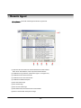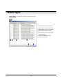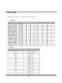
1
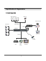
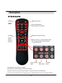
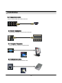
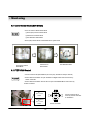
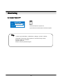
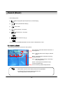
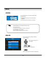
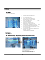
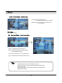
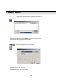
Triplex MP4 SDVR
Stand Alone Type
DVR SYSTEM
MANUAL
Firmware 2.0 Version
Revision Date : 2005. 01. 31.
041130
050131
• MODIFICATION CONTENTS
Firmware ver 2.0
Modification Date: 2005.01.31
Please refer the below message to confirm the modify contents.
1. PTZ CONTROL
* ADD PRESET FUNCTION : FOR PELCO-D PROTOCOL
* ADD SWING FUNCTION : FOR DONGYANG CAMERA (D-MAX)
2. CD-RW ( CD Read&Write Burner )
* ADD CD-RW FUNCTION FOR DATA BACK-UP
3. IE BROWSER
•ADD IE BROWSER ( ALLOW FOUR USERS MONITORING AT THE
SAME TIME )
• INDEX
■ CHAPTER 1 . ( Specification & System Organization )
1.1 Specification ------------------------------------------------------ 7
1.2 Product Contents List ------------------------------------------------ 8
1.3 System Organization
------------------------------------------------ 9
■ CHAPTER 2 . ( Description )
2.1 Front Panel ------------------------------------------------------- 10
2.2
Rear
Panel
2.3
Remote
----------------------------------------------------
Controller
-----------------------------------------
11
12
■ CHAPTER 3 . ( Installation )
3.1 Hard Disk Installation ------------------------------------------------ 13
3.2 Camera Connection
------------------------------------------------ 15
3.3 Monitor Connection
------------------------------------------------- 15
3.4 Computer Connection
3.5 Network Connection
--------------------------------------------- 15
------------------------------------------------ 15
3.6 Alarm/Relay/PTZ Connection ------------------------------------------- 16
3.7 Power Connection
-------------------------------------------------- 16
3.8 Finishing Installation
------------------------------------------------- 16
※ Hard Disk Format ------------------------------------------------- 17
■ CHAPTER 4 . ( Monitoring )
4.1 System Power ON --------------------------------------------------- 18
4.2 Select Screen Mode
4.3 Convert Screen Mode
------------------------------------------------- 18
------------------------------------------------ 19
4.4 Control PTZ/Focus --------------------------------------------------
19
4.5 System Power OFF -------------------------------------------------- 20
■ CHAPTER 5 . ( Search )
◎
Go
to
Search
-----------------------------------------------
21
5.1 Search by Date/Time ------------------------------------------------ 21
5.2 Search by Event -------------------------------------------------- 22
• INDEX
■ CHAPTER 6 . ( Menu )
◎
Go
to
Menu
-----------------------------------------------------
24
◎ Menu Initial ------------------------------------------------------- 24
6.1
Display
---------------------------------------------------------- 25
6.2
Record
---------------------------------------------------------- 25
6.2.1 Size/Rec. Rate/Quality ---------------------------------------- 25
6.2.2 Timer Recording Setup -------------------------------------26
6.2.3 Motion Detection Setup -------------------------------------- 27
6.2.4 Alarm Recording Setup ----------------------------------------- 27
◎ Time Recording Weekly Setup -------------------------------------- 28
◎ Partial Motion Region Setup
6.3
Camera
----------------------------------------- 29
---------------------------------------------------------- 30
6.3.1 Status/Title Setup ----------------------------------------------- 30
6.3.2 Covert/PTZ Setup --------------------------------------------- 30
6.3.3 Color Setup -------------------------------------------------- 31
6.4
AUDIO
--------------------------------------------------------
31
6.4.1 Audio Recording Setup ------------------------------------------- 31
6.4.2 Live Audio Setup ------------------------------------------------ 32
6.5
ALARM
---------------------------------------------------------
32
6.5.1 Alarm Input Setup ----------------------------------------------- 32
6.5.2 Relay Output Setup ---------------------------------------------- 33
6.6
SYSTEM
-------------------------------------------------------- 33
6.6.1 Date/Time --------------------------------------------------- 33
6.6.2 Network ------------------------------------------------------- 34
6.6.3 Buzzer Setup --------------------------------------------------- 34
6.6.4 Password ----------------------------------------------------
34
6.6.4.1 Administrator Password --------------------------------------- 34
6.6.4.2 Manager Password ------------------------------------------ 35
6.6.4.3 Operator Password ---------------------------------------- 35
6.6.4.4 Network Password --------------------------------------- 35
6.6.5 Disk Write Mode ----------------------------------------------- 36
6.6.6 System Information --------------------------------------------- 36
6.6.7 Factory Default ------------------------------------------------ 36
• INDEX
6.7 CD-RW Back-up ----------------------------------------------------- 37
■ CHAPTER 7 . ( Remote Agent )
◎
System
Requirement --------------------------------------------
38
◎ DVR Remote Agent 1.0 Installation ------------------------------- 39
7.1 Monitoring
7.1.1 Function Introduction
------------------------------------------ 41
7.1.2 Screen Division Selection ----------------------------------------- 42
7.1.3 PTZ Control --------------------------------------------------- 42
7.1.4 Selection Network ID -------------------------------------------- 42
7.1.5 AVI File Conversion
7.1.6 Color
-------------------------------------------- 43
Adjustment ------------------------------------------- 43
7.2. Search
7.2.1 Function Introduction ------------------------------------------- 44
7.2.2 Search Method ------------------------------------------------- 45
7.2.3 Search Option
--------------------------------------------- 46
7.3. Setting
7.3.1
Connection
ID
Setup
-----------------------------------
51
7.3.2 Option Setting ----------------------------------------------- 52
■ CHAPTER 8
Time
Table
------------------------------------------------------
53
PTZ
Protocol
---------------------------------------------------
54
PTZ
Control
-----------------------------------------------
55
8.1
PTZ
Reset
8.2
Swing
Cross cable
--------------------------------------------------
56
------------------------------------------------
56
making
tip
------------------------------------------- 57
• SUPPLEMENT LIST
1.
PTZ Control
1.1 PTZ Control -------------------------------------------------- 77
1.2 FOCUS/IRIS Control ------------------------------------------- 77
1.3 PRESET Control ----------------------------------------------- 78
11.4 SWING Control ----------------------------------------------- 78
2. Cross Cable Making Tip -----------------------------------------
79
• Specification & Organization
1.1 Specification
7
• Specification & Organization
1.2 Product Contents List
Please confirm the contents when you open packing.
① Basic Contents
DVR Machine
User’s Manual
12V Adaptor
Remote Controller
② Option Contents
80GB HDD
VGA OUT Install Kit
8
Remote Client Program
Install CD
Power Cable
AAA Battery X 2
• Specification & Organization
1.3 System Organization
Alarm Sensor #1-4
Relay Out
Remote Client PC
Alarm Input/Out
Camera #1-4
NETWORK
TCP/IP
AVR 400s
Video In
Image Printer
Video Out
Remote
Controller
VCR
VGA
Monitor
9
AV Monitor
• Description
2.1 Front Panel
2
3
1
4
12
6
5
10
9
7
8
11
1. Power : System Power On/Off.
2. LED Indicator : Indicate Present System Situation
( POWER: System On/Off , RECORD: Record On/Off ,
NETWORK: Client Network Connect On/Off , ALARM: Alarm Sensor On/Off )
3. Channel Select Button : When Select Channel or Input Password
1
4. SCR Mode : When Select Screen Division Mode or Rotation Mode
5. Menu : Go to System Menu
6. Search : Go to Search Mode for Searching Recorded Video
7. PTZ/Focus : Go to Camera PTZ/Focus Control
8. Remote Controller Sensor Input
9. Search Controller : Searching Recorded Video or Control Menu & PTZ/Focus
10. Enter : Press Enter to Apply Changing Setup
11. Return : Cancel Setup or Return Previous Mode
12. CD-RW Burner
Tip
• Power Button is soft style to Prevent System Failure by wrong operation.
• Channel Selection Button is prior to SCR mode.
• When Remote Controller Sensor Input is blocked by something, it cause
remote controller do not work properly.
• When press any button, it operate with Beep Sound.
10
1
• Description
2.2 Rear Panel
①
③
②
④
⑥
⑨
⑤ ⑦ ⑧
⑪
⑫
⑩
⑬
① Video In : BNC Port which Connected DVR & Camera (4 Camera Connectable)
② Loop Back : Output DVR Camera Video to Loop Back Port (4 BNC Port)
③ Monitor Out : Output DVR Video when connected AV Monitor
④ Spot Out : Output Spot-out Video to AV Monitor
⑤ NTSC/PAL : Select NTSC or PAL Type
⑥ VGA Out : Connected VGA Card to Output Video at Computer Monitor (Optional)
⑦ SVHS : Output Video to Connect SVHS Terminal
⑧ Audio Out : Output Recorded Audio
⑨ Audio In : AV Terminal which Connected Camera #1~4 for Input Audio
⑩ Ethernet (TCP/IP) : Connect Port for LAN Cable (Possible to Remote Survey to Connect
to Client)
⑪ Alarm/Relay/RS-485 : Connect Port for Sensor & Relay, PTZ
⑫ RS-232C : For Program Debug & Expand Connection (NOT AVAILABLE NOW)
⑬ DC Power Input Terminal : Power Supply by DC 12V Adaptor
Tip
• When System Installation, Please Connect when System Off.
• Please Use Specific Adaptor when Power Supply.
19
• Description
2.3 Remote Controller
POWER
System
ON/OFF
MENU: Open menu
Channel Select Button
(4ch Available, #1~4 Button)
RETURN
ENTER: Apply Setup Change
Cancel
Setup or
Return to
Previous
Search Controller : Control Playback Option
(EX. Speed of Playback, Move on Menu,
1Control PTZ/Focus)
Change Screen Open
Mode
Search Mode
PTZ/IRIS
Mode
• Unused Button’s Description is Omitted.
• Every Button is Operated Same as Front Panel Button.
• Remote Controller can Operate when Remote Controller Sensor Input Part Reacted.
※ If there are many DVRs at the same place, they are reacted together when press remote controller
20
• Installation
3.1 Hard Disk Installation
① Jumper Setup Master or Slave
• Jumper Setup as Master or Slave refer to Explanation of
Surface Hard Disk
• Jumper is located at Hard Disk Data Cable or Rear
of Hard Disk
1
1 Side
• If One Hard Disk Installation, Setup as Master
1 If Two Hard Disk Installation, Second One Setup as Slave
‼ When Hard Disk Add or Exchange, Must System Off
Properly (Power Button System Off). If not, it’s a cause of
Fatal Error of Disk.‼
※ Example of Samsung HDD Jumper Setup
• Refer to General Pin Setting in Jumper Pin Setting on HDD Surface
• When One HDD Install, Setup Pin as Master
1 and Connect Pin at the Left end of Jumper
• When Two HDD Install or Add HDD, One is for Master and
Other is for Slave. Slave Setup has No Pin.
1 1 the
• When More than Two HDD Installation, Setup as Master & Slave
1 to Connect One IDE Cable the Same Method of Above
!!Please use HDD which can supply higher than UDMA66.!!
② IDE Cable Connection to Main Board
• Confirm the IDE Cable Inside of Product
• Among the Three Connector, Indicated Blue Color 1
Connector Must be Connected with Main Board. Other 1
Connectors Connected with HDD
13
• Installation
② Connect IDE Cable to Hard Disk
• Insert Disk, Red Cable Head to Power Cable Plug
• Connect Power Cable to Hard Disk in the Same Way
※ If One HDD Install, Connect with End of Connector (Black)
Recommended.
If Add HDD, Connect with Middle Connector (Gray)
Recommended.
One HDD Installation
Two HDD Installation
③ After Finishing Cable Connection, Attach Hard Disk with Screw & Bracket
Tip
ㅡMaster, Slave?
• IDE Hard Disk can connect two equipment at one
cable (port). For the purpose of prevent confusing, two
equipment named ‘Master’ & ‘Slave’. ’Master’ is one
hard disk or first hard disk and ‘Slave’ is below second
hard disk.
14
• Installation
3.2 Camera Connection
Connect Camera at BNC Port in Back Side Panel.
3.3 Monitor Connection
Connect Monitor Terminal or S-VHS Terminal to Monitor
3.4 Computer Connection
Connect VGA OUT Terminal to Computer Monitor
3.5 Network Connection
Connect Ethernet Terminal and Network Cable
15
• Installation
3.6 Alarm/Relay/PTZ Connection
①
②
③
① ALARM
Alarm Input - ‘IN1, IN2, IN3, IN4’ : Connect Sensor Input by Channel
‘GND’ : Connect Ground System
② RELAY
Alarm Output – ‘NO, NC’ : After Checking Alarm Output Type (Normal Open or Normal Close)
and Connect to ‘NO, NC’
‘COM’ : Connect Remain Grounding Conductor
③ RS-485
Connect PTZ Camera – ‘D+, D-’ : Connect PTZ Camera Control Line (+ , – Terminal)
RS485
D+
D-
PTZ 14 Pin Cable
⑨ R+
⑩ R⑪ T+
⑫ T-
3.7 Power Connection
Connect DC Power Input Terminal and Specific Adaptor
3.8 Finishing Installation
System Start by Power Button after Finishing Installation
16
• Installation
※ Hard Disk Format
- If Do Not New Hard Disk Format, System Can’t Recognize the HDD.
So there’s Same Situation of No HDD. Please Format HDD when Insert New HDD.
(Only Display Possible, Not Work Menu & Search)
Che c king Ha rd Disk Drive s ...
Disk0 [SANSUNG SP00 0 2N]
Tota l 1 Ha rd Disk Drive Found.
Ne w Syste m Disk De te c te d .
All Disks will b e form a tted .
Form a t All Disks ? NO (0 )
1. Power On
2. New HDD Format
(Select Play , Backward Play Key)
3. System Start
(Initial Mode)
SETUP
Use r
Pa sswo rd
17
Ad m inistra tor
• Sys pwr on
4.1 System Power ON
• Press Power Button to Start System
• After Checking Hard Disk, Need input Password to
1 Operation
• Initial Screen View Mode is Quad Division Mode
1 and Recording Mode
CAMERA
2004/01/01
00:00:00
Picture for Power On
after Finishing Installation
• Each Channel Indicate Camera Name & Recording Status
• Present Time & Date Indicate at Monitor Central Lower Side
Tip
• Check System Condition at LED
POWER : Showing System On/Off
RECORD : Showing Record On/Off
NETWORK : Showing Client Connection Status
ALARM : Lighting when Sensor Alarm Activate
4.2 Select Screen Mode
• Select One Channel among 4 Channels
• Move to One Enlargement Watch Mode when Quad Screen Division Mode
• Move to One Enlargement Watch Mode when Rotation Mode
18
• Monitoring
4.3 Convert Screen Mode (SCR MODE)
• User can Select 3 Kinds Watch Mode
SCR MODE
① Quad (4CH) Division Watch Mode
② Selected 1CH Watch Mode
③ 4CH Rotation Watch Mode
• Quad (4CH) Watch Mode is Initial Mode when System Start
Quad (4CH) Division
Watch Mode
Selected 1CH
Watch Mode
4CH Rotation Mode
4.4 PTZ/FOCUS Control
• Control Camera PTZ (Pan/Tilt/Zoom) & Focus (Only Useable for Proper Camera)
PTZ/FOCUS
• Press PTZ/FOCUS Button to Open PTZ Menu at Right-Under Side and Control by
1 Search Controller
• Press PTZ/FOCUS Button Second Time to Open FOCUS/IRIS Menu and Control by
Search Controller
PTZ CTL
UP
LEFT RIGHT
DOWN
1
Control Camera PTZ &
Focus by Search Controller
on PTZ Menu
FOCUS/IRISCTL
UP
LEFT RIGHT
DOWN
Search Controller
19
• Monitoring
4.5 System Power OFF
SHUTDOWN
Use r
Pa sswo rd
Ad m inistra tor
• Press Power Button to System Off
• Input Password and Press Enter to Shutdown System
Tip
• System Log-On Possible ID : ‘Administrator’, ‘Manager’, ‘Operator’, ‘Network’
Administrator: All Function Access (System On, Shutdown, Setup, Search)
Manager: System On and Search
Operator: System On
Network: Connect by Remote Program
20
• Search
⊙ Go to Search Mode
SEARCH
Se a rc h
1. Sea rch by Da te/Time
>
1. Sea rch by Da te/Time
>
• Press Search Button and Log-In
Administrator or Manager
• Use Direction Key to Move Menu
ENTER
Search Recorded Data
RETURN
• To Open Each Menu Press Enter
• Return to Previous.
(Move to Previous Menu or Exit Search
1 Mode and Return to Watch Mode)
5.1 Search by Date/Time
- Possible to Search Recorded Date & Time
Ma r
14
15
16
21
22
28
29
① Move Cursor to Selected Date in Calendar
(Recorded Date & Time Indicated by Gray Color)
20 04
Sun Mon Tue We d Thu
1
2
3
4
10
11
7
8
9
Fri Sa t
5
6
12
13
17
18
19
20
23
24
25
26
27
30
31
② Press Enter to Open Selected Date
③ Recorded Time Appear to Under Side
④ Press Enter at Selected Time
(One Scale is 15 Minutes)
⑤ Menu Disappear and Output Recorded Video
1
2
3
4
5
6
7
8
9
10
11
12
13
14
15
16
17
18
19
20
21
• Showing Recorded Date & Time at Left-Upper Side
Watch Mode.
Condition at Right-Under Side.
1 as
1 Showing Playing
• Channel Selection Button in Watch Mode & SCR Mode
are Apply the Same as Search Mode.
(But Menu, Search, and PTZ/Focus Buttons are Exception)
21
1 Button
2004/01/01
00:00:00
>
• Search (Event)
• Control Playing Video
①
: Basic Playing Mode (Normal Speed (1X) Forward Playing)
②
: Normal Speed Backward Playing
③
: Pause Video
④
: Fast Forward (2 ~ 64 Speed)
⑤
: Fast Backward (2 ~ 64 Speed)
⑥
: Same Function as # ④,⑤
※ Press Normal Forward/Backward Button in Pause, Move to Next/Previous Frame.
5.2 Search by Event
- Searching Video with Event Occurrence to Set up Period
Set up Period to Select Start Date & Finish Date for
Searching Event
Alarm : Searching Alarm Event during the Selected
1
Period
Motion : Searching Motion Detected Event during
the Selected period .
1
Timer : Searching Schedule Change or Recording
1
Setup Change Event
System : Searching Power On/Off Event (etc.)
Concerned System Event
Event List Showing at Below Output Window
Tip
• Alarm, Motion, System can be Select plural by Check (V)-(ENTER)
• To Change Setup, Press Enter and Press Direction Key
After Changing Setup, Press Enter to Exit.
22
1
• Search
• Date : Indicate Event Occurrence Order & Date
Time : Indicate Event Occurrence Time
Event : Indicate Event Contents & Camera No.
• Event Searching Method
① User can Search Event Using by Direction key
② Search Event to Press Enter at Selected Event
from Event Occurrence Time
③ Control Video is the same way as Time Mode Control
Tip
• The Search by Event is not Base on Video, but Event Occurrence Time.
31
• Menu
⊙ Go to Menu
① Press Menu Button on Front Panel in Watch Mode
SETUP
Use r
② Ask Password
③ Input Password Using by Channel Select Button
1 [1][2][3][4])
Ad m inistra tor
Pa sswo rd
Tip
④ After Input Password Press Enter to See Menu
• Initial Administrator, User, Network Password is 1234.
• Showing Password as *
• Changing Password (MENU->6.System->4.Password )
• Only Watch Mode can go to Menu.
(Search & PTZ/Focus Mode can’t move to Menu)
⊙ Menu Initial
• Every System Setup can Change or Maintain
1 at Menu (6 Setup)
M ENU
•
1. Displa y
>
2. Rec ord
>
3. C am era
>
4. Audio
>
5. Ala rm
>
6. System
>
Move to Menu Using by Up &
Down Button
•
ENTER
To Open Detail Menu or to Apply Input
•
RETURN
Return to Previous Menu or Return to Watch Mode
24
• Menu
6.1 Display
- Video Setup for Watch Mode
1.
Date/Time : Date & Time Mark On/Off
2.
Title : Camera Name On/Off
3.
Status : Record Condition Mark On/Off
(Recording: Red, Pre-recording : Green)
4.
Border : Border Mark On/Off
4CH Division Watch Mode
5.
Border Color : Select Border Color
(White, Blue, Red, Yellow, Green, Gray)
6.
Sequence Dwell : Setup Rotation Cycle Time
Sec.) when 4CH Rotation Mode at Watch Mode
7.
Spot-Out Dwell : Setup Spot-Out Time Cycle
Sec.) to Transmit Video
8.
Deinterlace Mode : Remove Screen Spread on High
Resolution , Low Frame
※Only Applying When D1(704X480)
6.2 Record
- Setup Image Record
6.2.1 Size/Rec.Rate/Quality – Setup Recording Resolution, Compression Rate, Quality
-Camera : Indicate Camera No. to Setup
-Size : Setup Resolution
-Rec.Rate : Setup Compression Rate
-Quality : Setup Quality of Recording Video
25
when
(1~60
(1~60
• Menu
• Size : 352*240, 704*240, 704*480
Rec.Rate : Possible to Select (1~30)
Quality : Possible to Select 3 levels (High, Low, Standard)
• Indicate Frame No. to Control Size & Rec. Rate
Overlimit Recording Capacity
Tip
• If Frame Over, Showing a Message ‘Overlimit Recording 1
Capacity’ and Impossible to Change Size & Rec. Rate
• When Setup, Please Refer to Below NTSC & PAL Type
NTSC : 352*240(120fps), 704*240(60fps), 704*480(30fps)
PAL : 352*288(100fps), 704*288(50fps), 704*576(30fps)
• Possible to Setup Size & Rec. Rate, Quality per Each Channel
• When Applying Change Setup, Press Enter,
When Cancel Change Setup, Press Return.
1
6.2.2 Timer Recording Setup – Record On/Off or Time, Motion Setup
• Camera : Indicate Camera No. to Setup
• Record : Record On/Off
• Start : Setup Recording Start Time (0~24 hr)
• Stop : Setup Recording Finish Time (0~24 hr)
* Recording Time is between Start Time and Finish Time.
• Motion : Motion Detection Recording On/Off
(Record Setup must be ‘On’, when Motion Detection
Recording.)
26
1
• Menu
6.2.3 Motion Detection Setup – Motion Detection Area & Sensitivity
• Camera : Indicate Camera No. to Setup
• Sensitivity : Control Sensitivity (1~100)
Large No. is More Sensitive.
• Region : Setup Motion Detect Range
Entirely – Setup Entire Screen
Partially – Setup Partial Screen
• When Choose Region as Partially, Move to Partial
Range Setup. Press Enter After Partial Range Setup
1 to Finish Region Setup.
1
• Pre-Motion Duration : Setup Pre-Motion Duration Time.
1
(1~5 sec)
• Post-Motion Duration : Setup Motion Detect Recording 1
Time after Motion Detected (5sec~3min)
6.2.4 Alarm Recording Setup – Recording Setup for Alarm Activated
• Camera : Indicate Camera No. to Setup
• Record : Setup Record On/Off when Alarm Activated
• Start : Setup Alarm Recording Start Time (0~24 hr)
• Stop : Setup Alarm Recording Finish Time (0~24 hr)
• Pre-Alarm Duration : When Alarm Recording, Setup
1 Start Recording Time before Alarm Activate (1~5sec)
• Post-Alarm Duration : Setup Alarm Recording Time
1 after Alarm Activate (5sec~3min)
Tip
• Motion Setup Work by Time Schedule and Alarm Schedule Work Independently.
27
• Time recording
⊙ Time Recording Weekly Setup
①
②
Weekly mode Setup at Record Setup
Scheduled Region Indicated Yellow
③
④
After ‘Deselect’ Schedule, Activated Region by
Press ‘ENTER’ and Select Date & Time to Move
Cursor
After Selecting Region and Press ‘ENTER’ Again to
Finish Schedule Setup (Red)
⑤
⑥
• Select All : Entire Region Select
• Deselect All : Cancel Region
• Save & Exit : Save Changing Setup & Exit
• Cancel : Cancel Changing Setup & Exit
Setup Date & Time Schedule in the Same Way.
After Finishing Schedule Setup,
Press ‘Return’ for Save & Exit
28
• Menu
⊙ Partial Motion Region Setup
:Non-Activate Move Cursor
①
:Activate Partial Setup Cursor
:Partial Setup Finish Cursor
②
Region Initial View
④
When Select Multi Region,
Using Direction Key in ② to
Expand Non-Activate Region
⑦
:Non-Activated Region
③
Move Cursor by Direction Key and
Press Enter at Selected Region
⑤
Press Enter again to see Region
as a Blue Color and Setup NonActivate Region
⑥
Press Enter to Select Multi
Activate Region
Non-
Same Method as ④⑤, Possible to
Expand Non-Activated Region
⑧
• Select All : Select Entire Region
• Deselect All : Cancel Region Setup
• Save&Exit : Save the Change Setup & Exit
• Cancel : Cancel Change Setup & Exit
For Reducing Partial Region,
Cancel Non-Activate Region in
Same Way as ④⑤
When Finishing Partial Region
Setup, Press Enter to Save &
Exit
29
• Menu
6.3 Camera
- Setup Camera
6.3.1 Status/Title Setup – Camera Connection Status & Camera Name Setup
• Camera : Indicate Camera No. to Setup
• Status : Indicate Camera Status
(Connected/Disconnected)
• Title : Setup Camera Name to Show Left-Upper Side
Tip
• Title Input Method
1
Using Direction Key, Up & Down Keys for Alphabet A~Z, Numerical No. 0~9
Left-Right Keys for Move to another Letter.
6.3.2 Covert/PTZ Setup
• Camera : Indicate Camera No. to Setup
• Covert : Setup Covert On/Off
*What’s Covert?
When Covert On Watch Mode, Display Video is 1
Hidden, but Recording is On.
• PTZ Address : Select PTZ Camera Address
• PTZ Protocol : Select Kind of PTZ Camera
• Baud Rate : Setup PTZ Communication Speed
(2400, 4800, 9600 BPS)
※PTZ Supplied Protocol :
Samsung(MRX-1000), HoneyWell(GC/GMC-755 Zoom)
Kalatel(KTD-312), Panasonic(WV-CS850),
Panasonic(WV-CSR604), PELCO-D, PELCO-P,
Sensormatic-ADPT8, Vicon(surveyor99), Sunin DSC-230
D-MAX ,HoneyWell(GC-655N)
30
1
• Menu
6.3.3 Color Setup – Control Video Color
• Camera : Indicate Camera No. to Setup
• Bright : Control Monitor Bright
• Contrast : Control Monitor Contrast
• Color : Control Monitor Color
• Tint : Control Monitor Tint
* All Setup Possible to Control 0~100
6.4 Audio
- Setup Audio
6.4.1 Audio Recording Setup – Audio In Setup
• Camera : Indicate Camera No. for Setup
• Audio Rec. : Setup Recording On/Off from External 1
Audio In Terminal
• Audio Ch. : Setup Audio In Terminal Channel &
1
Audio Output Camera
Tip
• User can Listen Saved Audio with Saved Video
• Audio Check in Search is Possible Only Normal Speed (1X) Forward 1
Playing at 1CH Mode (Audio Recorded Channel)
31
• Menu
6.4.2 Live Audio Setup – Audio Out Setup
• Live Audio : Audio Output ON/OFF
Live Audio Output from Audio In Terminal
• Monitoring Ch. : Select Channel for Audio Output
1
Nr. 1~4 Audio In
6.5 Alarm
- Setup Alarm & Relay
6.5.1 Alarm Input Setup – Alarm Sensor Setup
• Alarm : Indicate Alarm Input Terminal No.
• Status : Setup Alarm Sensor Connection Status
(Connected/Disconnected)
• Camera : Input Camera No.1~4 to Connect Alarm
• Type : Setup Alarm Sensor N/Open, N/Close Type
Tip
• Generally Alarm Sensor can be Divided Two Types.
Normal Open Type is Open Sensor Electrically and Reacted when
Signal is Connected.
Normal Close Type is Close Sensor Electrically and Reacted when
Signal is Disconnected.
32
1
1
• Menu
6.5.2 Relay Output Setup – Alarm Relay Setup
• Alarm : Indicate Alarm Input Terminal No.
• Relay Out : Setup Relay Connect with Alarm Sensor
• Mode : Setup Reacted Relay as Latched/Transparent Mode
• Duration : Setup Reacted Relay Time
(5sec~5min or Until key-in)
• Relay Type : Setup Relay Type N/Open or N/Close
Tip
• Latched/Transparent
Latched – When Sensor Alarm Activated, Relay Reacted in Setup Duration
Transparent – Relay Reacted Temporary During Sensor Alarm Activate
6.6 System
- Basic Environment Setup
6.6.1 Date/Time – Date & Time Setup
• Date : Setup Present Date (YYYY-MM-DD).
(If Time Setup to Past Date, Ask Delete Data for the Past Date.
NO->Date/Time No Change, YES->After Delete Past Data and Change Date/Time )
• Date Format : Select Date Output Type (Ex: 2004-00-00, 2004/00/00)
• Time : Setup Present Time
• Time Format : Setup Time Type as 12 Hour Base or 24 Hour Base
• Daylight Saving : Summer Time Applying Status
33
1
• Menu
6.6.2 Network – Setup TCP/IP
• IP Address : Input IP Address
• Gateway : Input Gateway IP for Internet Server
• Subnet Mask : Input Subnet Mask IP
• Network Speed : Setup Network Speed
(Network Speed from System, Depend on Network Status)
※ If Change Network Setup, New Change Apply
when after Rebooting.
6.6.3 Buzzer Setup – Setup Key Sound to Speaker
• Alarm Input : Alarm On/Off when Alarm Activate
• Videoloss : Alarm On/Off when Camera Disconnected
• Disk Full : Alarm On/Off when Hard Disk Full
• Disk Error : Alarm On when Hard Disk Error
• Key Input : Setup Key Input Sound
6.6.4 Password – Setup Password
6.6.4.1 Administrator Password – Setup Menu & System On/Off
• Current Password : Input Current Password (Initial Password : 1234)
• New Password : Input New Password
• Re-enter the Password : Re-Confirm New Password
• Save&Exit : Applying New Password
34
• Menu
6.6.4.2 Manager Password – Possible System On & Search, But Can’t Change Setup
• Current Password : Input Current Password
(Initial Password : 1234)
• New Password : Input New Password
• Re-enter the Password : Re-Confirm New Password
• Save&Exit : Applying New Password
6.6.4.3 Operator Password – Possible System On, But Can’t Change Setup and Search
• Current Password : Input Current Password
(Initial Password : 1234)
• New Password : Input New Password
• Re-enter the Password : Re-Confirm New Password
• Save&Exit : Applying New Password
6.6.4.4 Network Password – Setup Remote Connection Program Password
• Current Password : Input Current Password
(Initial Password : 1234)
• New Password : Input New Password
• Re-enter the Password : Re-Confirm New Password
• Save&Exit : Applying New Password
35
• Menu
6.6.5 Disk Write Mode – Setup Hard Disk
• Disk Overwrite : Select Overwrite Permission when
1
Hard Disk Full
O N: Overwrite Hard Disk from Oldest Data
OFF: When Hard Disk Full, Stop Recording and
Buzzer Activate (Refer to Menu 6.3 Buzzer Setup)
1
• Disk Initialize Now : Refreshment Hard Disk
All Recorded Data Deleted
• When Select Disk Initialize, Alarm Message Showing.
1 Select ‘Yes’ to Start Disk Initialize.
※When Change Disk Overwrite ON/OFF Mode, the Change will be Applied from Changing Time.
For Example When Overwrite On Mode & HDD Full, Change to Overwrite Off Mode and then it will be Applied New Data
Fill HDD Full after Changing Time.
6.6.6 System Information – Product information (Version etc)
• S/W Version : Indicate Software Version of the Product
• H/W Version : Indicate Hardware Version of the Product
• Video Signal Type : Indicate Video Signal Type
• Disk Size : Indicate Hard Disk Capacity
• Number of HDD : Indicate Present Installed HDD No.
• IP Address
• MAC Address
6.6.7 Factory Default – Every Setup Initializing
• Press Enter to Start Initialize
• Showing Warning Message and Press OK to Run Initialize
• If do Factory Default, Every Setup is Initialized, but
1 Saving Image is Not Erase.
36
• Menu ( CD-RW Back-up )
6.7 CD-RW Back-Up
⊙ Go to Menu
① Press Menu Button on Front Panel in Watch Mode
SETUP
② Ask Password
Ad ministra tor
User
③ Input Password Using by Channel Select Button
1 [1][2][3][4])
Pa ssword
④ After Input Password Press Enter to See Menu
SETUP
• Use the Up-Down button to move the cursor
1 . Displa y
>
2 . Re c ord
>
3 . Ca m e ra
>
4 . Audio
>
5 . Ala rm
>
6 . Syste m
>
7 . Ba c k Up
>
to 7. Back Up icon .
Note : Move to Icon Start and press
Enter to CD burning after all
set .
7 . Ba c k Up
CD-RW Proceed
CRW-S2 82 AX
1
•1. CD-RW Burner Display
Sta rt Tim e
2 00 5. 01 .3 1 1 5:2 1
2
• 2. Fill the start time in
End Time
2 00 5. 01 .3 1 1 5:2 4
3
• 3. Fill the end time in
De vic e
All
ASUS
Ch1
C h2 >
Sta rt
C h3
4
Ch4
• 4. Channel selection
• 5. Video backup selection
Vide o
>
5
Audio
>
• 6. Audio backup selection
6
• 7. Event backup selection
Title
End Time
Ba c k Up C D
8
>
Event
• 8. Title backup selection
7
36
• Remote Agent
• System Requirement
① Main Board (CPU): Celeron 500-700(Minimum), Pentium 4 recommend
② OS: More than Windows 98,DirectX 7.0A
③ Memory (RAM): More than 128 M
④ VGA: Overlay YV12 Format Graphic Card
All Radeon, Nvidia (Above Geforce) Matrox (Above G400) Compatible Video Card
※ Above DIVX Codec 5.1 (When Use Media Player)
• DVR Remote Agent 1.0 Install
① Open CD-ROM Drive and Run DvrRemoteAgentSetup.exe and then Appear Setup Menu
② Close All Running Software and Press Next to Move Next Step
38
• Remote Agent
③ Ask designate Folder to Install DvrRemoteAgent 1.0,
Recommend Basic setup c:\program files:\DvrRemote Agent 1.0
Click Next
④ Showing Progress of Copy of Files
⑤ Appear DirectX 7.0a Install Menu. If DirectX Version Lower than 7.0a, Press Yes to Start Install
39
• Remote Agent
⑥ When Finishing Installation, System must be Restarted. Click ‘Yes’
⑦ Finish DvrRemoteAgent 1.0 Program Installation
40
• Remote Agent
7.1 Monitoring
7.1.1 Function Introduction
③
①
④
⑤
⑥
⑦
⑧
⑨
⑩
⑪
②
⑫
① Main Screen Image : Showing Present Surveillance Camera Image
② Camera Selection Button : Indicate Connected Camera No. & Select Image to Click Camera No.
③ Hide/Exit : Hide DVR Client Window or Exit Program
④ Time Output : Showing Present Time & Date
⑤ Search : Move to Search Mode to Play Video
Setup : Move to Setup to Change Network Setup or Option
⑥ I/D Selection : Select I/D to Connect Server
⑦ Connect : Connect Server (AVR 400S)
Disconnect : Disconnect from Server
⑧ Screen Division Selection : Change Screen Division Mode
⑨ Save by AVI file : Transmission Live Image Save by AVI File
⑩ Color Adjustment : Adjust Color of Live Transmission Image
⑪ PTZ Control Button : Control Camera PTZ & Focus
⑫ Exit : Exit DVR Client
41
• Remote Agent
7.1.2 Screen Division Selection
• 1*1 View : Showing One (1) Video which User Selected
(Selection Video by Camera Selection Button)
• 4*4 View : Quad Screen Division Mode
• Scenario View : One Large Screen Mode Showing One by One (1*1 View)
1
Depend on User Selection Time (Not Work Screen Division Mode)
• Full Screen View : Present Video Move to Full Screen Mode
Mouse Double Click when Return Previous
*Mouse Double Click Make the Same Function as Full Screen.
7.1.3 P/T/Z Control
• P/T/Z Controller : Camera P/T/Z Control by Direction Keys
• FOCUS/ZOOM Select Button : Focus or Zoom Control by +,- Button
• +,- Control Button : Focus or Zoom Control
7.1.4 Selection Network I/D
Network Information Icon
• Select I/D to Connect Server.
• I/D can be Add, Change, and Delete at Setup
• Click Network Information Icon, to See a
1 Popup Window for Connected Server I/D, 1
IP, and Port Information.
42
• Remote Agent
7.1.5 AVI File Conversion
• Click AVI Conversion Button to Start AVI File Conversion
• During AVI Conversion Showing a Message and before
1 Click ‘Stop” Save AVI File continuously
• Press ‘Stop’ to Open Designate File Name & Saving
1 Location, and Save AVI File
• Saved AVI File can Open Ordinary Moving Picture Player
• Moving Picture Player Codec Version is Above Divx 5.1.
7.1.6 Color Adjustment
• Click Controller Possible to Control Color
• Change Brightness, Contrast, Saturation from 0 to 100
• Click OK to Finish Changing Setup
43
• Remote Agent
7.2 Search Mode
7.2.1 Function Introduction
①
③
④
⑤
⑥
⑦
②
⑧
① Search Screen : Playing Selected Video
② Search Bar : Search & Indicate Camera Recording Situation by Time Bar
③ LIVE : Return to Watch Mode
SETUP : Open Setup to Change Network Setup or Option
④ Screen Division Selection : Change Playing Screen Division Mode
⑤ SEARCH Option : Backup Video or Search Event
⑥ Camera Selection Button : Select Camera at the 1*1 View
⑦ Quick Search : Find Image to Designate Date & Time
⑧ Search Controller : Control Playing Video
44
• Remote Agent
7.2.2 Search Method
②
①
⑤
③
④
① Indicate 0~24 Hour
② Indicate Recording Situation (Blue : No Record, Yellow : Recorded Image at the Time)
③ Search Bar : Select Video to Drag Mouse Search Controller in Recorded Area
④ Indicate Camera Channel to Confirm Camera Recording Situation
⑤ Refreshment Recording Information Situation Window by Camera Channel
⑥ If Connected Channel is 5 or More, Another Channel will be Scroll.
45
⑥
• Remote Agent
7.2.3 Search Option
③Save Image
①Backup
⑤Log Search
②Backup Play
⑥Event Viewer
④Print Image
① Backup – Backup Image from Server to Remote PC
• Backup Time : Designate Backup Time (Now or Later)
• Designate Backup Date & Time when Later
• Source :
Designate Backup Image Data Length to
Input Start Time & End Time.
• Channel : Check Camera Channel for Backup
• Select All
Deselect All
•Press OK to Open Backup Status & Start Backup.
•When Finish Backup, Back Status Window Disappear & Backup Data Save at Hard Disk
Root Folder in Remote PC.
46
1
1
• Remote Agent
① Showing Image (Possible to Only 1*1View Mode)
② Backup File Open to Play First Video
Ex. : ch02_04131730_04131735.rec ( Backup File for # 2 ch. Apr.13, 17H30M ~17H35M )
③ Indicate Present Playing Video Camera Channel No.
④ Indicate Present Time & Date and Possible to Search Time & Date
⑤ Search Controller, the Same Way of Previous Search
Tip
• Backup Play Setup in Search Mode is the Same as DVR Player,
so it can be Run Independently without Running Remote Program.
47
• Remote Agent
③ Save Image – Capture Image & Saving Image at Hard Disk or Removable Disk
• Click ‘Save Image’ Icon During Playing Video
• Designate File name, File Type (JPG,BMP), and Location and Press Saving
• Conversion and Saving Image from Remote Viewer
③ Print Image – Present Image Capture and Print Out Image
• During Play Video, Click ‘Print Image’
• After Selecting Printer, Start Image Printing
• Print Out Remote Viewer Image
48
• Remote Agent
③ Log Search – Find Video Centering around Event Log at Server
① Input Start Time and End Time at the Selected Date to Search Event
When Press Search Button, Event Output at the Below Window
② Indicate Event Log Order No. ( Max Event Log No. of 1 Page is 100 )
③ Indicate Event Occurred Camera No.
④ Indicate Event Occurred Time & Date
⑤ Indicate Event Detail Description
⑥ Move to Previous Page
⑦ Move to Next Page
⑧ Move to User Select Page
⑨ After Select Event, Move Search Bar in Search Mode
⑩ Return to Search Main to Play Event Image
49
• Remote Agent
④ Event Viewer – Showing Present Event in Server & Find Image
① Indicate Event Occurred Order No.
② Indicate Event Occurred Camera No.
③ Indicate Event Occurred Time & Date
④ Indicate Event Detail Description
⑤ After Select Event, Move Search Bar
1 in Search Mode
⑥ Return to Search Main to Play
1 Selected Event Image
① ②
③
④
⑤
⑥
50
• Remote Agent
9.3 Setting
①
①
②
②
⑦
③
⑧
④
⑨
⑤
⑩
③
④
⑥
7.3.1 Connection ID Setup
① ID Status : Indicate Present Saving ID & ID Information
② Input Name to Add or Amend ID
③ Input IP Address to Add or Amend Server
④ Indicate Port No.
⑤ Input ID for Connecting Server
⑥ Input Password for Connecting Server
⑦ Click to Input New ID Information
⑧ After Input All ID Information, Add ID Information at ID Status
⑨ After Amend All ID Information, Applying Change ID Information
⑩ Selected ID Delete at ID Status
Tip
• Initial ID & Password is ‘NETWORK’ & ‘1234’
51
• Remote Agent
7.3.2 Option Setting
① Control Screen Rotation Time in Scenario Mode at Watch Mode
(Possible to Setup from 1~300 sec.)
② Possible to Select Event Kind Plurally from Server. Remote Client Only can See Selected Event.
(System, HDD, Alarm, Video, REC)
③ Setup Print-Out Image of Information Display from Server (Name, Date, Resolution)
④ Designate Backup Image Saving Folder at Remote PC
52
•Time Table
■ DVR Storage Capacity Calculation (Based on 80GB HDD)
1. Calculation
1. Result
53
• PTZ Protocol List
■ PTZ Protocol List
※ Present DVR supply only PTZ/FOCUS/IRIS function. (Planning other feature)
54
• PTZ CONTROL
1. PTZ Control
PTZ/FOCUS
• Press PTZ/FOCUS Button to Open PTZ Menu at Right-Under Side and Control by
1 Search Controller
• When Press PTZ/FOCUS Button by Turns, Focus/Iris, Preset, Swing Menu will Appear at
the Right-Under Side and possible to Control by Search Controller.
PTZ CTL
UP
LEFT RIGHT
DOWN
FOCUS/IRISCTL
UP
LEFT RIGHT
DOWN
Fast
Backward
Backward
Play
Play
Fast
Forward
Search Controller
PRESET
NUMBER:1
NUMBER CHANGE:UP/DOWN
SET:F1
GOTO:F2
SWING
MODE:PAN SWING
NUMBER CHANGE:UP/DOWN
FIELD CHANGE:LEFT/RIGHT
SET:F1
RUN:F2
1.1 PTZ Control
① Control Camera Movement by ‘Faster’, ‘Slower’, ‘Backward Play’, ‘Play’ Button (Up,Down.Left,Right).
② Zoom In & Out by ‘Fast Backward’, ‘Fast Forward’ Button.
③ Keep Press Button Make Continuous Movement.
1.2 FOCUS/IRIS Control
① Control Iris by ‘Faster’, ‘Slower’ Button.
② Focus On by ‘Backward Play’, ‘Play’ Button.
③ Zoom In & Out by ‘Fast Backward’, ‘Fast Forward’ Button.
④ Keep Press Button Make Continuous Movement.
55
• PTZ CONTROL
8.1 PRESET Control
PRESET
NUMBER:1
NUMBER CHANGE:UP/DOWN
SET:F1
GOTO:F2
① By Preset Function, Possible to Setup Direction and Focus of PTZ Camera.
② After Selecting Position at PTZ Control Mode, Save Data at Preset Mode.
③ Setup ‘NUMBER’ from 1 to 128 by ‘Faster’ & ‘Slower’ Button.
④ Save by Front Panel Key No.1 Button or F1 Button on Remote Controller.
⑤ To Move to Saved Location, Press Front Panel Key Button No.2 or F2 Button on Remote Controller.
8.2 SWING Control
① SWING Function Dedicate Each No. of Saved Preset and Swing as Pan or
SWING
MODE:PAN SWING
NUMBER CHANGE:UP/DOWN
FIELD CHANGE:LEFT/RIGHT
SET:F1
RUN:F2
Tilt.
② Changing Mode by Backward Play Button.
Changing Setup by Faster, Slower Button.
③ PAN SWING MODE : Rotate Left , Right Side.
TILT SWING MODE : Rotate Up, Down Side.
START PRESET : Select Starting Point. (1~128)
END PRESET : Select End Point. (1~128)
SWING TIME : Select Halt Time as Each Point. (1~64sec)
SWING SPEED : Select Moving Speed of Camera. (1~64)
④ Save by Front Panel Key No. 1 Button or F1 Button on Remote Controller.
⑤ For Start SWING Mode, Press Front Panel Key No.2 or F2 Button on Remote Controller.
56
• Cross Cable Making Tip
■ Cross Cable Making Tip
1. LAN Plug
2. LAN Cable
A Part
B Part
3. Connection Method
① Connect LAN Cable A part and LAN Plug by Order as One to One.
② Compare to LAN Cable B part & A part, Replace Order No.1 & 3, No. 2 & 6.
③ Connect LAN Cable B part No. 3 to LAN Plug No.1 and Connect the Next by Order.
57