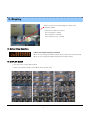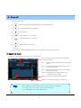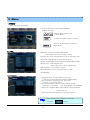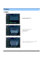
1
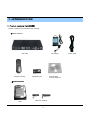
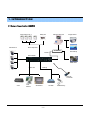
EZ-REAL DVR
USER'S MANUAL
Revision Date : 2006. 12. 15.
• INDEX
• CHAPTER 1. Specification & System organization
1. Product Contents List -------------------------------------------------------- 1
2. System Organization --------------------------------------------------------- 2
• CHAPTER 2. Description
1. Front Panel --------------------------------------------------------------- 3
2. Rear Panel --------------------------------------------------------------- 4
3. Remote Controller ---------------------------------------------------------- 5
• CHAPTER 3. Display
1. System Power ON ---------------------------------------------------------- 6
2. Screen View Selection ------------------------------------------------------ 7
3.Display Mode ------------------------------------------------ 7
4. PTZ/FOCUS Control -------------------------------------------------------- 8
5. System Power OFF --------------------------------------------------------- 8
• CHAPTER 4. Search
⊙ Go to Search Mode --------------------------------------------------------- 9
1. Search by Date/Time ------------------------------------------------------- 9
2. Search by Event ----------------------------------------------------------- 10
• INDEX
• CHAPTER 5. MENU
⊙ Go to Menu -------------------------------------------------------------- 11
⊙ Go to System Setup -------------------------------------------------------- 11
1 Display ------------------------------------------------------------------ 12
1.
2. Camera ----------------------------------------------------------------- 14
3. Audio ------------------------------------------------------------------- 17
4. System ------------------------------------------------------------------ 18
5. Event/Sensor ------------------------------------------------------------- 23
6. Disk Management ---------------------------------------------------------- 26
⊙ Go
G to Record
d Menu
M
-------------------------------------------------------- 27
2
1. Recording Operation -------------------------------------------------------- 27
2. Continuous/Motion Record Schedule -------------------------------------------- 28
3. Alarm Record Schedule ----------------------------------------------------- 29
⊙ Go to Archiving ----------------------------------------------------------- 30
1. CD-RW and USB Back up --------------------------------------------------- 30
• CHAPTER 6. CLIENT
⊙ Remote Program Install ----------------------------------------------------- 31
1. Function Introduction ------------------------------------------------------- 33
2. Setting
g ------------------------------------------------------------------ 34
3. Monitoring --------------------------------------------------------------- 41
4. Search ------------------------------------------------------------------ 45
5. Web Client --------------------------------------------------------------- 52
1. INTRODUCTION
1. Product contents List (400SN)
Please Confirm the Contents When open Package.
① Basic Contents
AVR-400S
Remote Controller
12V Adaptor
AAA Battery X 2
② Option Contents
HDD
VGA OUT Install Kit
1-1
Remote Client
Program Install CD
Power Cable
1. INTRODUCTION
1. Product contents List (400SN)
Please Confirm the Contents When open Package.
① Basic Contents
AVR-400SN
Remote Controller
12V Adaptor
AAA Battery X 2
② Option Contents
HDD
CD-RW
1-2
Remote Client
Program Install CD
Power Cable
1. INTRODUCTION
2. System Organization (400S)
Alarm Sensor #1-4
Relay Out
Remote Client PC
Camera #1-4
Alarm Input/Out
NETWORK
TCP/IP
AVR-400S
Video In
Image Printer
Video Out
O
Remote
Controller
VCR
VGA
Monitor
2-1
AV Monitor
1. INTRODUCTION
2. System Organization (400SN)
Alarm Sensor #1-4
Camera #1-4
Remote Client PC
Relay Out
Image Printer
Alarm Input/Out
NETWORK
AVI Backup
TCP/IP
AVR-400SN
Video In
WEB Client
B k
Backup
Video Out
Remote
Controller
VCR
VGA
Monitor
AV Monitor
2-2
CD-RW
USB Memory
2. Description
1. Front Panel (400S)
①
③
②
④
⑥
⑤
⑦
⑧
⑩
⑨
① Power : System Power On/Off
② Led indicator : Indicate Present System Status information.
( POWER: System On/Off , RECORD: Record On/Off , NETWORK: Client Network Connection Status
ALARM: Alarm Sensor Detection Status )
③ Channel Select button : Select Channel or Input Password.
④ SCR MODE : Select Screen Division Mode or Rotation Mode.
⑤ MENU : Go to System Menu.
⑥ SEARCH : Go to Search Mode for Searching Recorded Data.
⑦ PTZ/FOCUS : Go to Camera PTZ/FOCUS Control.
⑧ Remote Controller Sensor Input.
⑨ Search Controller : Searching Recorded Data or Control menu & PTZ/FOCUS.
⑩ ENTER : Apply Changing Setup.
⑪ RETURN : Cancel Setup or Return Previous Mode.
Tip
• Power Button is Soft Style to Prevent System Failure by Wrong Operation.
• Channel Selection Button is Prior to SCR Mode.
• When Remote Controller Sensor Input is Blocked by Something, it Cause
1 Remote Controller do NOT Work Properly.
• When Press any Button, it Operate with Beep Sound.
3-1
⑪
2. Description
1. Front Panel (400SN)
②
③
⑤
①
④
⑥
⑦
⑧
⑨
⑩
⑪
⑫
① Power : System Power On/Off.
② Remote Controller Sensor Input.
③ CD-RW : CD-RW Device for Backup.
④ Led Indicator : Indicate Present System Status Information.
( POWER: System On/Off , RECORD: Record On/Off , NETWORK: Client Network Connection Status
ALARM: Alarm Sensor Detection Status )
⑤ Channel Selection Button : Select Channel or Input Password.
⑥ SCR MODE : Select Screen Division Mode or Rotation Mode.
⑦ SEARCH : Go to Search Mode for Searching Data.
⑧ MENU : Go to System Menu.
⑨ PTZ/FOCUS : Go to Camera PTZ/FOCUS Control.
⑩ Search Controller : Searching Recorded Data or Control Menu & PTZ/FOCUS.
⑪ ENTER : Apply Changing Setup.
⑫ RETURN : Cancel Setup or Return to Previous Mode.
Tip
• Power Button is Soft Style to Prevent System Failure by Wrong Operation.
• Channel Selection Button is Prior to SCR Mode.
• When Remote Controller Sensor Input is Blocked by Something, it Cause
1 Remote Controller do NOT Work Properly.
• When Press anyy Button,, it Operate
p
with Beep
p Sound.
• In Case of CD-RW, the Real Appearance will be Differ from the above Picture
1 Depends on its Model.
3-2
2. Description
2. Rear Panel
①
③
②
④
⑥
⑨
⑤ ⑦ ⑧
⑪
⑫
⑩
⑬
① Video In : BNC Port for Connection of DVR & Camera. (4 Camera Connectable)
② Loop Back : Output DVR Camera Video to Loop Back Port. (4 BNC Port)
③ Monitor Out : Output DVR Video to AV Monitor.
④ Spot Out : Output Spot-out Video to AV Monitor.
⑤ NTSC/PAL : Select NTSC or PAL Type.
⑥ VGA OUT : Output Video to a Computer Monitor by Connected VGA.
⑦ SVHS : Output Video by Connected SVHS.
⑧ Audio Out : Output Audio Data.
⑨ Audio In : Audio Input Terminal Related with #1~4 Camera.
⑩ Ethernet (TCP/IP) : Port for Cross cable. (Possible to Remote Surveillance.)
⑪ Alarm/Relay/RS-485 : Connect Port for Sensor, Relay, & PTZ.
⑫ RS-232C : Connect Port for Program Debug
Debug.
⑬ DC Power Input : Power Supply by DC 12V Adaptor.
Tip
• When System
y
Installation,, Please Install under System
y
Power Off Status.
• Please Use Specific Adaptor when Power Supply.
4
2. Description
3. Remote Controller
POWER
MENU: Open Menu
System
ON/OFF
Channel Selection Button
(16ch Available, #1~4 Button)
RETURN
ENTER: Apply Setup Change
Cancel Setup
or Return to
Previous
Search Controller : Control Playback Option,
Menu Movement, PTZ/Focus Control
Change
Screen Mode
Open
Search Mode
PTZ/IRIS Mode
• Unused Button’s Description is Omitted.
• Every Button is Operated Same as Front Panel Button.
• Remote Controller can Operate when Remote Controller Sensor Input Part Reacted Each Other.
※ If there are many DVR at the same place, they are reacted together when press remote controller.
5
3. Display
1. System Power ON
• Press Power Button to Start System
• After Checking Hard Disk, Need input Password to
1 Operation
• Initial Screen View Mode is Quad Division Mode
1 and Recording Mode
CAMERA
Picture of Power On
after Finishing Installation
2005/01/01
00:00:00
• Each Channel Indicate Camera Name & Recording Status
• Present Time & Date Indicate at Monitor Central Lower Side
Tip
• Check System Condition at LED
POWER : Showing System On/Off
RECORD : Showing Record On/Off
NETWORK : Showing Client Connection Status
6
3. Display
When connect by the RemoteAgent or Web Client ,
Indicator appear.
• Indicate the network condition.
Green: Network is stable.
Blue: Network is unstable.
Red: Network is veryy unstable.
2. Screen View Selection
• Select One Channel among 16 Channels
• Move to One Enlargement Watch Mode when Quad Screen Division Mode
• Move to One Enlargement Watch Mode when Rotation Mode
3. DISPLAY MODE
• User can Select various Watch Mode
• Quad
Q d (16CH) W
Watch
t hM
Mode
d iis IInitial
iti l M
Mode
d when
h S
System
t
St
Startt
7
3. Display
4. PTZ/FOCUS Control
• Control Camera PTZ (Pan/Tilt/Zoom)
• Press PTZ Button to Open PTZ Menu
• Each icon mean the button of front keyboard.
• Press PTZ button one more time, then another menu
• Control each function by front keyboard.
appear.
• F: Focus
I: IRIS
5. System Power Off
• Press Power Button to System Off
• Input Password and Press Enter to Shutdown System
Tip
• System Log-On Possible ID : ‘Administrator’, ‘Manager’, ‘User’
Administrator: All Function Access (System On
On, Shutdown
Shutdown, Setup
Setup, Search)
Manager: System On and Search
User: System On
8
4. Search
⊙ Go to Search Mode
• Press Search Button and Log-In
Administrator or Manager
• Use Direction Key to Move Menu
• To Open Each Menu Press Enter
1
• Press Return button to Move to Previous Menu or
Exit Search Mode and Return to Watch Mode.
1. Search by Time
- Possible to Search Recorded Date/Time
① Move Cursor to Selected Date in Calendar.
(Date of record data is shown green color.)
② Press Enter to Open Selected Date.
③ Recorded Time Appear to Upper Side.
④ Press Enter at Selected Time.
(One Scale is 15 Minutes)
⑤ Menu Disappear and Output Recorded Video.
• Showing Recorded Date & Time at Left-Upper Side
1 as Watch Mode.
1 Showing Playing Condition at Right-Under Side.
• Channel Selection Button in Watch Mode & DISPLAY
1 Button are Apply the Same as Search Mode.
(But Menu, Search, and PTZ Buttons are Exception)
9
2004/01/01
00:00:00
>
4. Search
• Control Playing Video
①
: Basic Playing Mode (Normal Speed (1X) Forward Playing)
②
: Normal Speed Backward Playing
③
: Pause Video
④
: Fast Forward (2 ~ 64 Speed)
⑤
: Fast Backward (2 ~ 64 Speed)
⑥
: Same Function as # ④,⑤
※ Press Normal Forward/Backward Button in Pause, Move to Next/Previous Frame.
2. Search by Event
- Searching Video with Event Occurrence to Set up Period
Set up Period to Select Start Date & Finish Date
for Searching
g Event
Alarm : Searching Alarm Event during the Selected
1
Period
Motion : Searching Motion Detected Event during
1
the Selected period .
Timer : Searching Schedule Change or Recording
1
Setup Change Event
System
y
: Searching
g Power On/Off
/
Event ((etc.))
1
Concerned System Event
Event List Showing at Below Output Window
Channel: Choose the channel for searching.
Tip
• Alarm, Motion, System can be Select plural by Check (V)-(ENTER)
(V) (ENTER)
• To Change Setup, Press Enter and Press Direction Key
After Changing Setup, Press Enter to Exit.
10
5. Menu
⊙ Go to Menu
① Press SETUP Button
② Ask Password
③ Input Password Using by Channel Select Button
④ After Input Password Press Enter to See Menu
Tip
• Initial Administrator, Manager, User Password is 1234.
• Showing Password as *
• Changing Password (System setup->System -> User management )
• Only Watch Mode can go to Entering setup.
(Search & PTZ/Focus Mode can’t move to Menu)
⊙ Go to System setup
• Choose the “system setup”
11
5. Menu
1 Di l
1.Display
- Video Setup for Watch Mode
• Every System Setup can Change or Maintain
1 at Menu (6 Setup)
•
Move to Menu Using by Up
& Down Button
•
•
ENTER
To Open Detail Menu, press “the Enter”
RETURN
Return to Previous Menu or Return to
Watch Mode
1-1. OSD
• Status Bar : Record Condition Mark On/Off
(Recording: Red, Pre-recording : Green)
• Camera Title: Setup Camera Name to Show Left-Upper Side
• Event Icon: Indicate the menu location by icon
• Border : Border Mark On/Off when 4CH Division Watch Mode
• Border Color : Select Border Color
(White, Blue, Red, Yellow, Green, Gray)
• Motion Sensor : Set Up Motion Sensor
• Alpha Blending: Choose the transparency(1~100)
• GUI Blending
1-2. MONITOR
• Sequence Dwell : Setup Rotation Cycle Time
(1~60 Sec.) when 4CH Rotation Mode at Watch Mode
• Spot-Out
p
Dwell : Setup
p Spot-Out
p
Time Cycle
y
(1~60 Sec.) to Transmit Video
• De-interlace Mode : Remove Screen Spread on High
Resolution , Low Frame ※Only Applying When D1(704X480)
• Alarm Pop-Up Mode: When alarm happen, Alarm happened
channel Pop-up
• Alarm Pop-Up Dwell: Alarm Pop-up Time(1~60Sec.)
Tip
12
• When finishing that change the setup data,
Press the
certainly.
5. Menu
1-2. SEQUENCE
• Activation : Activation On/Off
• List : Sequence Title
•
•
•
•
Choose Add to Add Sequence
Input Sequence Title
Choose Activation
Save and Exit
• When input sequence title, You can use virtual
keyboard by pressing enter button.
13
5. Menu
2C
2.Camera
- Setup Camera
2-1. Camera Title
• Covert : Setup Covert On/Off
*What’s Covert?
When Covert On Watch Mode, Display Video is Hidden, but Recording is On.
• Title : Setup Camera Name by Virtual keyboard
• Input the title by “Enter” after choose by up and down
button.
2-2.
2
2. Color Setup
• Control
C t l th
the M
Monitor
it B
Bright,
i ht C
Contrast,
t t C
Color,
l
Ti
Tintt
• All Setup Possible to Control 0~100
• Setup Channel by Channel
14
5. Menu
Tip
※ How to use the Virtual Keyboard
• Input the title by “Enter” after choose by up and down button.
• Press the
button for shift then choose the other characters.
2-3. PTZ Setup
• Address : Select PTZ Camera Address
• PTZ Protocol : Select Kind of PTZ Camera
• Baud Rate : Setup PTZ Communication Speed
(2400, 4800, 9600,19200, 38400 BPS)
• Enter
button and setup the detailed PTZ
※PTZ Supplied Protocol : Samsung(MRX-1000)
Samsung(MRX 1000), Samsung(SCC641),Honeywell(SD1)
Samsung(SCC641) Honeywell(SD1)
Honeywell((GMC),Lilin(Fastdome), Fastrax(Ⅱ), GC(655N),
D-MAX, Sunin DSC-230, Scan Dome-Ⅱ, Vicon,Philips8560-700
Sensormatic,Panasonic(WV-CS850), Panasonic(WV-CSR604),VRX-2101
Kalatel(KTD-312), PELCO-D, PELCO-P,Dynacolor(D7722)
15
5. Menu
2-4. Motion Sensor
• Choose the Partial Motion Region channel by
• Move Cursor by Direction Key and Press Enter at
channel
Selected Region
• Sensitivity: 1~10
• Select All : Select Entire Region
• Deselect All : Cancel Region Setup
• Cancel : Cancel Change Setup & Exit
• Save & Exit : Save the Changes & Exit
16
5. Menu
3 S
3.
Sound
d
3-1. Audio
- Audio Setup
• Live Audio : Audio Output ON/OFF
Live Audio Output from Audio In Terminal
• Audio Monitoring Channel: Select Channel for Audio Output
1
Nr. 1~4 Audio In
• Network Audio TX: Choose the Audio transmission
• Network Audio RX: Choose the Audio receive
3-2. Buzzer
- Buzzer Setup
• Keypad : Setup keypad buzzer
• Remocon : Setup remocon buzzer
17
5. Menu
4. System
- Basic Environment Setup
4-1. date/time
※ First of all, Timezone should be setup as your location.
• Date TIME: Setup Present Date
(If Time Setup to Past Date, Ask Delete Data for the Past Date.
NO->Date/Time No Change, YES->After Delete Past Data and Change Date/Time )
• Date Format : Select Date Output Type (Ex: 2005-00-00, 2005/00/00)
• Time Format : Setup Time Type as 12 Hour Base or 24 Hour Base
• Network Time Server: Setup Present Time by Time Server
Server.
• D.S.T: Daylight Saving Function On/Off
• Time
Ti
Zone
Z
Setup
S t
: Ch
Choose th
the ti
time b
by GMT standard.
t d d
Tip
※ How to Time setup
1 Setup Timezone as your location
1.
location.
2. Setup the Network Time server and press the “Sync” button.
3. If correct time is not getted automatically, setup the date/time manually.
4. If don’t follow as upper, you may have the time error and the recording data search error.
18
5. Menu
4-2. Network
• IP Address : Input IP Address
• Gateway : Input Gateway IP for Internet Server
• Subnet Mask : Input Subnet Mask IP
• DNS Server: Input DNS Server IP
• DDNS Server: Input
p DDNS Server IP
• Net Client Port : Input net client server
• Web Server Port : Input web server port
• Max TX Speed : Setup Max TX Speed
※ If Change Network Setup, New Change Apply
when after Rebooting.
• DHCP (Dynamic Host Configuration Protocol) : Indicate IP Address for the DVR Automatically
Automatically.
1.
2.
3.
4.
5.
Enter to ‘System -> Network’ on the Menu.
Setup DHCP On/Off.
DHCP Off : User Input IP Address by Himself.
DHCP On : After DHCP On, Reboot the System.
Can see the setup IP automatically at the system information.
• DDNS (Dynamic DNS): You can connect the DVR by the fixed domain name(ex.00115f000001.dvrlink.net) at
client or Web without entering the IP address.
※ If you use the DDNS, there is no necessity to enter again the IP Address every connection.
1.
2.
3.
4.
5.
6.
Enter to ‘System -> Network' on the menu.
Setup DHCP On or Enter the IP address.
Setup DDNS ON and reboot.
Enter to ‘System -> System information’ on the menu.
Confirm the MAC address.
The domain name is "MAC address.dvrlink.net".
EX) If Mac Address is 00-11-5f-00-b5-a7, the domain name is "00115f00b5a7.dvrlink.net"
7. If you connect by "00115f00b5a7.dvrlink.net"
"
" at client program or Web, you can connect the DVR.
• Web Service
• Net Client Service
Tip
※ 1. If your network connect at the router, please must port forwarding.
2. Please must enter the exact IP address,, DNS Server,, Gateway,
y, Subnet Mask.
3. Please must connect the DVR at External Network.
If you don't follow 1,2,3 , you can't receive the DDNS service.
19
5. Menu
4-3. Mail
• Server: Setup the mail server
• Setup by Virtual Keyboard after press the “ENTER”
• Port: mail server port
• Security: On/Off
• User & Password: input the DVR login user ID and Password.
20
5. Menu
4-4. User Management
User setup
• It is consisted 3 User Group as Administrator,
Manager, User.
• Total 7 user belong to 3 User Group can be made.
• Input User ID, Password.
• Choose the Group.
• Input the E-mail Address.
• It can edit User ID information.
• E-mail notification On/Off : 1. ON:
2. OFF:
• Input the E-mail by Virtual Keyboard.
21
5. Menu
4-5. System Information
• S/W Version: Server Firmware Version
• H/W Version : Hardware version
• Video Signal Type: NTSC or PAL
• Disk Capacity: used HDD capacity of the total HDD capacity
• IP Address: DVR’s IP Address
• MAC Address: Fixed MAC address of the DVR
22
5. Menu
4-6. Factory Default
• Press “Press” to Start Initialize.
• Showing Warning Message and Press OK to Run Initialize.
• If do Factory Default, Every Setup is Initialized, but Saving Image is Not Erase.
5. Event/Sensor
5-1. HDD Event
• Drive: HDD connected location
• Smart Alarm: On/Off
• Check interval: HDD checking Time
23
5. Menu
5-2. Alarm Input
• Operation: Setup Alarm Sensor Connection Status
(enable/disable)
• Type : Setup Alarm Sensor N/Open, N/Close Type
5-3 Alarm Output
5-3.
※ Setup each channel when alarm, videoloss, motion are
happened.
• Channel : Select Channel
• Mode: Setup Reacted Relay as Latched/Transparent
Mode.
• Type: Setup Relay Type N/Open or N/Close.
• Operation: Setup Relay Connect with Alarm Sensor.
• Duration: Setup Reacted Relay Time. (5sec~5min or Until
key-in)
• HDD Event: Alarm On/Off when HDD has the problem.
Tip
• Latched/Transparent
Latched – When Sensor Alarm Activated, Relay Reacted in Setup Duration
Transparent – Relay Reacted Temporary During Sensor Alarm Activate
24
5. Menu
5-4. Buzzer out
• Buzzer On/Off
• Operation: Setup Buzzer.
• Mode: Setup Reacted Relay as Latched/Transparent Mode.
• HDD Event: Buzzer On/Off when HDD event is happened.
• Duration: Buzzer time(5sec~5min
(
or Until key-in)
y )
• setup each channel when alarm, videoloss, motion are
happened.
25
5. Menu
5-5. E-mail Notification
• If the alarm, videoloss, motion and HDD event are happened,
send the notification at the E-mail.
• Choose the function by up and down button.
6 Disk Management
6.
• Disk Overwrite : Select Overwrite Permission when Hard Disk Full
ON
N: O
Overwrite
i H
Hard Disk
i k ffrom Ol
Oldest Data
OFF: When Hard Disk Full, Stop Recording and Buzzer Activate
• Format : Refreshment Hard Disk. All Recorded Data Deleted
26
5. Menu
⊙ Go to Record Menu
• Choose “Record Menu”
1. Recording Operations
• Schedule Mode: Choose the DAILY or WEEKLY.
• Pre-Event Recording Time : Setup Pre-Event recording Time.
(1~5 sec)
• Post-Event Recording Time: Setup Post-Event recording Time.
(1~5 sec)
27
1
1
5. Menu
2. Continuous/Motion Record Schedule
2-1.
• Setup each channel
• Put the choose area at here and press “Enter” button.
2-2.
• Continuous record setup
• Setup each channel
• Motion record setup
• Setup each day
28
5. Menu
3. Alarm Record Schedule
3-1.
• Setup each channel
• Alarm record setup
• Put the choose area at here and press “Enter” button.
3-2.
• Alarm record setup
• Setup each channel
• Setup
S t
each
hd
day
29
5. Menu
⊙ Go to Archiving
1. CD-RW and USB Back Up
① Device : Indicate CD-RW Model and USB MEMORY Model Automatically.
If you use the
th CD
CD-RW
RW and
d USB memory ((or USB HDD) ttogether,
th
it can choose the CD-RW and USB by up and down Button.
② From : Select Start Backup Time.
③ To : Select End Backup Time.
④ Channel & Video/Audio Selection : Select Channel, Video, & Audio for Backup.
⑤ Title : Change the Title of Backup by virtual keyboard.
⑥ Event : Select Attach Event Text File in Backup.
⑦ Start : Start Backup.
Tip
• Compatible CD Writer Models are LG(GCE-8526B,GCE-8527B),
SAMSUNG(SW-252F, TS-H292A, SH-522C),ASUS(CRW-5232AS),GIGABYTE(GO-R5232B)
• Compatible USB memory stick Models are LG(Royal,mobile,mirror), IMATION(iflash),Memorive PRO+
and Compatible USB HDD is CUTIE(FHD-254)
CUTIE(FHD-254).
• Inside of Backup CD,USB Including Necessary Codec for Playback (IMM4 Install File).
• In case of RW Possible CD, Please Delete Previous Data on PC for Recording Again.
30
6. Client
• System Requirement
①
②
③
④
Main Board (CPU): Pentium-500(Minimum), Pentium 4 recommend
OS: Higher than Windows 98,DirectX 7.0A
Memory (RAM): More than 128 M
VGA: Graphic card that support the DIRECT-X
※IMM4 Codec (When Playback Backup File)
• DVR Remote Agent Install
① Open CD-ROM Drive and Run DvrRemoteAgentSetup.exe and then Appear Setup Menu
② Close All Running Software and Press Next to Move Next Step
31
6. Client
③ Ask designate Folder to Install DvrRemoteAgent, Recommend Basic setup c:₩program files:₩Remote Agent
Pro. Click Next.
④ Showing Progress of Copy of Files
⑤ Finish DvrRemoteAgent Program Installation
32
6. Client
1. Function Introduction
③
①
④
⑤
⑥
⑦
⑧
⑨
⑩
⑪
⑫
②
⑭
⑬
① Main Screen Image : Showing Present Surveillance Camera Image
② Camera Selection Button : Indicate Connected Camera No. & Select Image to Click Camera No.
③ Hidden/Exit : Hide DVR Client Window or Exit Program
④ Time Output : Showing Present Time & Date
⑤ SEARCH : Move to Search Mode to Play Video
Local/DVR SETUP : Move to Setup to Change Network Setup or Option
⑥ DVR Selection : Select I/D to Connect Server
⑦ Connect : Connect DVR
Disconnect : Disconnect from DVR
⑧
⑨
⑩
⑪
⑫
⑬
⑭
Screen Division Selection : Change Screen Division Mode
Save by AVI file : Transmission Live Image Save by AVI File
Event viewer : Showing Present Event in Server & Find Image
PTZ Control Button : Control Camera PTZ & Focus
Audio Button and Alarm : Control Two Way Audio & Mute and Alarm On/Off
Quit : Exit DVR Client
Connection Status : Showing the connected DVR.
33
6. Client
2 S
2.
Setting
tti
2-1. DVR List
②
①
②
③
④
⑤
①
③
Group list
DVR IInformation
f
i
Camera Position : Set camera position
Option Check
Add, modify, delete group
④
⑤
2-2. Add Group
②
① Click the “Add Group”
② Input the Group name, IP, Port.
Select ID and Input Password
③ Set
S t camera position
iti
④ Check option
Select live monitoring channel
①
③
④
34
6. Client
2 3 Option
2-3.
①
②
③
④
⑤
① Receive Event : Select Kinds of Event as Multiple. Remote Client Only Receive Selected Event.
(
(System,
HDD, Alarm, Video, REC))
② OSD Display : Select Screen Information. (Name, Date, Resolution)
③ Screen Switching Interval (sec) : During the Monitoring, Select Screen Rotation Interval Time
(From 1 sec. to 300 sec.)
④ Live Audio Monitoring Channel : Select Channel for Listening Audio at Remote Among 4Ch Audio.
⑤ Saving Directory : Designate Remote PC Backup Image Saving Folder.
2-4. DVR Server Remote Setup
• Choose the DVR for setup and click the “Setup” button.
36
6. Client
• Click DVR System Setup Tap, Password Input Window Open After Input Password, Setup Window Pop-up.
• DVR System Tap Indicated Only when Connect as Administrator.
• DVR System Setup Possible to Control Almost Every Setup at the Remote.
• When Activate Setup or Changing Setup at the DVR Server, It’s Impossible to Change Setup at the Remote.
• During System Setup at the Remote, DVR Server Setup Start Make to Close Remote System Setup Automatically.
① Record Setup
• Record Operations
- Schedule Mode: Weekly or Daily
- Sunday ~ Saturday
- Pre Event Recording Time: 0 ~ 5(Second)
- Post Event Recording Time: 5 ~ 180(Second)
• Alarm Recording Schedule
- Click the “Set: Button for Alarm Recording.
• Continuous/Motion record Schedule
- Click the “Set: Button for Continuous/Motion
record Schedule.
37
6. Client
② Camera Setup
• Status/Title Setup
- Setup for Each Camera (Connection Status or Camera
Name).
• Color Setup
- Setup Color for Each Screen.
• Covert/PTZ Setup
- Setup Each Camera Covert Function & PTZ Protocol.
• Motion Area
- Click the “Properties” button.
- Click the “Camera” Button.
- Setup about PTZ camera.
- Choose the area.
③ Audio Setup
• Live Audio Setup
- Live Audio & Two Way Audio Setup for Server.
38
6. Client
④ Event/Sensor Setup
• Alarm Input
- Setup for Each Channel Alarm Connection & Type.
• Alarm Out
-
Setup each channel when alarm, videoloss, motion are happened.
HDD Event: Alarm On/Off when HDD has the problem.
Operation: Setup Relay Connect with Alarm Sensor
Mode: Setup Reacted Relay as Latched/Transparent Mode
Type: Setup Relay Type N/Open or N/Close
Duration: Setup Reacted Relay Time (5sec~5min
Duration
(5sec 5min or Until key-in)
key in)
• Buzzer out
- Setup each channel when alarm, videoloss, motion are happened.
- Buzzer: On/Off
- Duration: Buzzer time(5sec~5min or Until key-in)
- HDD Event: Buzzer On/Off when HDD event happen
- Keypad : Setup Key Input Sound
- Remocon: Setup remocon Input Sound
• HDD E
Eventt
- Drive ID: HDD Connected location
- Smart Alarm: On/Off
- Temperature: HDD Temperature
- Polling Time: HDD Checking Time
• E-mail Notification
- If happen the alarm, videoloss, motion and HDD event, setup the notification at the E-mail.
- HDD Event: E-mail notification On/Off when HDD event is happened.
- Notification
Notification: On/Off
39
6. Client
⑤ System
S t
S
Setup
t
• System Info
- Possible to Watch DVR System Status.
• SMTP
- Setup the mail server and user’s E-mail.
• Users
- Setup the Users.
- Click the “Add” or “Modify” button.
• Disk Overwrite
- Setup DVR HDD Overwrite On/Off.
• Network Speed
40
6. Client
3. Monitoring
3.1 Selection Network I/D
• Select I/D to Connect Server.
• I/D can be Add, Change, and Delete at Setup
3.2 Screen Division Selection
• 1*1 View : Showing One (1) Video which User Selected
(Selection Video by Camera Selection Button)
• 4*4 View : 4 Screen Division Mode
9*9
9 View : 9 Screen Division Mode
•9
• 16*16 View : 16 Screen Division Mode
• Screen auto switching : One Large Screen Mode Showing One by One (1*1
View) Depend on User Selection Time (Not Work Screen
Division Mode)
• Full Screen View : Present Video Move to Full Screen Mode
Mouse Double Click when Return Previous
*Mouse
M
Double
bl Cli
Click
kM
Make
k the
h S
Same Function
i
as Fullll S
Screen.
Tip
※ Multi DVR Client
• 4EA DVRs can be control the live view, search the data, backup data and
setup about each channel at the same time.
• Refer to p48 about setup.
41
6. Client
• 9 Division Mode
• 16 Division Mode
3.3 P/T/Z Control
• Press the PTZ Button.
• P/T/Z Controller : Camera P/T/Z Control
by Direction Keys
• FOCUS/ZOOM Select Button : Focus
or Zoom Control
by +,- Button
• +,+ - Control Button : Focus or Zoom Control
42
6. Client
3.4 AVI File Conversion
• Click AVI Conversion Button to Start AVI File Conversion.
• During AVI Conversion Showing a Message and before
1 Click ‘Stop” Save AVI File continuously .
• ‘Press ‘Stop’ to Open Designate File Name
1 & Saving Location, and Save AVI File.
• Saved AVI File can Open Ordinary Moving
1 Picture Player or Backup Player.
• Moving Picture Player Codec Version Need
1 Higher than Divx 5.1 & IMM4 Codec.
3.5 Color Adjustment
• Click Controller Possible to Control Color
• Change Brightness, Contrast, Saturation from 0 to 100
• Click OK to Finish Changing Setup
43
6. Client
3.6 Event Viewer
① Indicate Event Occurred Order No.
② Indicate Event Occurred DVR No.
③ Indicate Event Occurred Camera No.
④ Indicate Event Occurred Time & Date
⑤ Indicate Event Detail Description
⑥ After Select Event, Move Search Bar in Search Mode
⑦ Return to Search Main to Play Selected Event Image
① ②
③
④
⑤
⑥
⑦
44
6. Client
4. Search
4.1 Function Introduction
①
③
④
⑤
⑥
⑦
②
⑧
① Search Screen : Playing Selected Video
② Search Bar : Search & Indicate Camera Recording Situation by Time Bar
③ LIVE : Return to Watch Mode
SETUP : Open Setup to Change Network Setup or Option
④ Screen Division Selection : Change Playing Screen Division Mode
⑤ SEARCH Option : Backup Video or Search Event
⑥ Camera Selection Button : Select Camera at the 1*1 View
⑦ Quick Search : Find Image to Designate Date & Time
⑧ Search Controller : Control Playing Video
45
6. Client
4 2 Search Method
4.2
①
⑥
⑤
③
②
④
⑦
① Indicate 0~24 Hour
② Indicate Recording Situation (Blue : No Record, Yellow : Recorded Image at the Time)
③ Search Bar : Select Video to Drag Mouse Search Controller in Recorded Area
④ Indicate Camera Channel to Confirm Camera Recording
g Situation
⑤ If Connected Channel is 5 or More, Another Channel will be Scroll.
⑥
⑦ Refreshment Recording Information Situation Window by Camera Channel
Select Date
Search Bar will Move,
if Input Date & Time
Play Video as Normal
Speed(Forward and Backward)
Search speed control
64 Times(Forward and Backward)
Program Exit
46
6. Client
4.3 SEARCH Option
③Save Image
①Archive
⑤Log Viewer
②Backup Play
⑥Event Viewer
④Print
① Archive – Backup Image from Server to Remote PC
• Time Range
Designate Backup Image Data Length to
Input Start Time & End Time.
1
• Channel : Check Camera Channel for Backup
• Include Audio : Check Audio Including when Backup
• Select All
Deselect All
• Press OK to Open Backup Status & Start Backup.
• When Finish Backup, Back Status Window Disappear & Backup Data Save at Hard Disk Root Folder in
Remote PC.
47
6. Client
② Backup Play (DVR Player) – Transfer to DVR Player
①
②
③
④
⑤
① Showing Image (Possible to Only 1*1View Mode)
② Backup File Open to Play First Video
Ex. : ch02_04131730_04131735.rec ( Backup File for # 2 ch. Apr.13, 17H30M ~17H35M )
③ Indicate Present Playing Video Camera Channel No.
④ Indicate Present Time & Date and Possible to Search Time & Date
⑤ Search Controller, the Same Way of Previous Search
Tip
• Backup Play Setup in Search Mode is the Same as DVR Player,
1 so it can be Run Independently without Running Remote Program.
• Backup Player & Ordinary Moving Picture Player Possible to Playback
Playback,
1 Real Time AVI Backup File can Display as the Same Format.
48
1
6. Client
③ Save Image – Capture Image & Saving Image at Hard Disk or Removable Disk
• Click ‘Save Image’ Icon During Playing Video
• Designate File name, File Type (JPG,BMP), and Location and Press Saving
• Conversion and Saving Image from Remote Viewer
④ Print – Present Image Capture and Print Out Image
• During Play Video, Click ‘Print Image’
• After Selecting Printer, Start Image Printing
• Print
Pi tO
Outt R
Remote
t Vi
Viewer IImage
49
6. Client
⑤ Log Viewer – Find Video Centering around Event Log at DVR.
②
①
③
④
⑤
⑥
⑦
⑧
⑨
⑩
① Input Start Time and End Time at the Selected Date to Search Event
When Press Search Button, Event Output at the Below Window
② Choose the DVR for searching the log.
③ Indicate
I di t E
Eventt L
Log O
Order
d N
No. ( M
Max E
Eventt L
Log N
No. off 1 P
Page iis 100 )
④ Indicate Event Occurred Camera No.
⑤ Indicate Event Occurred Time & Date
⑥ Indicate Event Detail Description
⑦ Move to Previous Page
⑧ Move to Next Page
⑨ Move to User Select Page
⑩ After Select Event, Move Search Bar in Search Mode
⑪ Return to Search Main to Play Event Image
50
⑪
6. Client
⑥ Event Viewer- Showing Present Event in Server & Find Image
① Indicate Event Occurred Order No.
② Indicate Event Occurred DVR No.
③ Indicate Event Occurred Camera No.
④ Indicate Event Occurred Time & Date
⑤ Indicate Event Detail Description
⑥ After Select Event, Move Search Bar in Search Mode
⑦ Return to Search Main to Play Selected Event Image
① ②
③
④
⑤
⑥
⑦
51
6. Client
5. Web Client
• WEB Client Connection
① Input IP Address or URL for DVR Server at the Internet Explorer Address Input Place.
② When Appear Active-X install Message, Please Click Confirm or Continue.
③ Showing Web Client Window at Internet Explorer.
④ All function is same with RemoteAgent.
52
6. Client
53