1
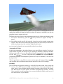
5
Quickstart
This section demonstrates how to take off and land with one of Orbiter‟s default
spacecraft, the Delta-glider. If you are using Orbiter for the first time, this will help to
familiarise yourself with some basic concepts of spacecraft and camera control. You
should also read the rest of this manual, in particular sections 6 and 8 on keyboard
and joystick interface, section 14 on instrumentation, section 15 on spacecraft controls, and section 17 on basic flight maneuvers.
Make sure you have configured Orbiter before launching your first simulation, in
particular the video and joystick parameters (see section 4). Once you have started
the Quickstart scenario, you can get the following scenario instructions also onscreen by opening the Help window with
.
Starting:
Select the Checklists|Quickstart scenario (see Section 4.1 on scenario selection),
and press the “Launch Orbiter” button to launch the scenario. Once the mission
has been loaded (this can take a few moments), you will see in front of you runway 33 of the SLF (Shuttle Landing Facility) at the Kennedy Space Center, Cape
Canaveral, Florida.
You are in control of a Delta-glider, a powerful futuristic spacecraft, aligned and
ready for takeoff.
You can always exit the simulation by pressing
or
, or by clicking
“Exit” on the main menu ( ). Orbiter saves the current simulation status in the
“(Current status)” scenario, so you can continue your flight later by selecting this
scenario.
Camera modes:
You are in an external camera mode, looking towards your ship.
You can rotate the camera around your ship by pressing and holding down the
key and pressing a cursor key (
) on the cursor keypad of your
keyboard. Alternatively you can press the right button on your mouse and drag
the mouse to rotate the camera. Or, if you have a joystick with a direction controller (“coolie hat”), you can use that as well.
To jump into the cockpit of your glider, press
. (
always toggles between
cockpit and external view of the spacecraft you are controlling).
In the cockpit, you can look around by rotating the camera with
or with the right mouse button or the joystick coolie hat.
To look straight ahead, press the
,
button.
To learn more about camera modes and views, have a look at Section 12.
Cockpit modes:
At the moment, you are in "virtual cockpit" mode - that is, you are inside a threedimensional representation of the glider cockpit, with the glass pane of the headup display (HUD) in front of you, and the instruments and controls arranged
ORBITER User Manual (c) 2000-2010 Martin Schweiger
24
around you. If you look back, you can even get a glimpse of your passengers in the
cabin behind you!
You can switch to a different cockpit mode by pressing
. Pressing
once will
open the "generic glass cockpit" mode with only the HUD and two onscreen multifunctional displays. Pressing
again will open a 2-D panel mode.
The panel can be scrolled by pressing a cursor key (
) on the cursor
keypad. To scroll the panel out of the way, press
. You should now be able to
see the runway stretching in front of you. Scrolling the panel is useful if you want
to see more of your surroundings. Also, if the panel is larger than your simulation
window, you can scroll different parts of the panel into view.
NEW
!
If the native resolution of the panel is larger than your simulation window, you
can use the mouse wheel to zoom the panel view in and out (this feature may not
be supported by all spacecraft types).
Some spacecraft have more than a single panel which can be accessed by pressing
in combination with a cursor key. If you press
, you will see the
glider‟s overhead panel with some additional controls. Pressing
twice will
bring up the lower panel with brake and gear controls. For now, switch back to
the main panel with
.
Not all spacecraft types support 2-D panels or 3-D virtual cockpits, but the generic cockpit mode is always available.
MFD instruments:
The most important and versatile instruments are the two multifunctional displays
(MFDs) in the centre of the instrument panel. Each MFD consists of a square LCD
screen and buttons along the left, right and bottom edges.
MFDs can be set to different modes: With the mouse, left-click the “SEL” button
at the bottom edge of one of the MFDs. (Alternatively, you can press
.
MFD keyboard interfaces always use
key combinations, where the left
key controls the left MFD, and the right
key controls the right MFD). You
will see a list of available modes.
Click on one of the buttons along the left or right edge to select the corresponding
mode. If you click the top-left button, the MFD switches to Orbit mode.
If you want to select a mode via keyboard, press
+
[letter], where [letter] is the keyboard character listed in grey next to the MFD mode in the selection
page.
Most modes have additional settings and parameters that can be controlled with
the buttons as well. The button labels change to indicate the various mode functions. For example, the Orbit mode has a button labeled “TGT”. This can be used
to display the orbit of a target object. Click this button – you will see a dialog box
to select a target object. Press
, type “iss” in the text box, and press
again. This will show the orbital parameters of the International Space Station in
the MFD display.
To see a short description of the available mode functions, click the “MNU” button at the bottom of the MFD (Alternatively, use
).
ORBITER User Manual (c) 2000-2010 Martin Schweiger
25
A description of standard MFD modes can be found in Section 14. Orbiter can
also be extended with add-on MFD modes, so you may see additional modes in
the list.
For now, switch the left MFD to Surface mode, and the right MFD to HSI mode.
Takeoff:
Your glider is capable of runway takeoffs and landings on Earth (and on any other
planet, if the atmospheric density is sufficient to provide aerodynamic lift).
For takeoff, engage main engines at full thrust. You can do this by pushing the
Main engine sliders at the left of the panel to the top using the mouse (make sure
you push both sliders simultaneously!), or by pressing
Num until engines
are at full throttle. If you have a joystick with throttle control, you can use that to
engage the main engines.
Your spacecraft will start to roll. You can check the speed (in meters/second) on
the AIRSPD indicator of the Surface MFD, or on the HUD (head-up display) – the
value in the green box at the top right of the screen.
When the airspeed reaches 100 m/s, pull back on the joystick to rotate, or press
and hold
Num.
Once clear of the runway, press
to raise the landing gear.
ORBITER User Manual (c) 2000-2010 Martin Schweiger
26
When the atmosphere is too thin to produce enough lift for a runway takeoff (for example when taking off from the Moon) or when no runway is available, you can use
the glider‟s hover engines to lift off:
Move the Hover slider on the instrument panel up by clicking and dragging with
the mouse. Alternatively, press the
Num key until hover engines are fully engaged.
Your glider should now lift off vertically. Once clear of the ground, engage main
engines. Note that a fully loaded and tanked glider may be too heavy to lift off vertically from Earth when the “realistic” flight model is used.
As you gain airspeed, you can gradually reduce hover thrust.
Atmospheric flight:
In the lower atmosphere, the glider behaves very much like an aircraft. Try the joystick controls for pitch, roll and yaw to get a feeling for handling at different altitudes.
Without a joystick, you can use the numerical keypad ( / Num for pitch,
/ Num
for roll, and
/ Num for yaw). The glider has powerful rocket engines, but their
performance depends on atmospheric pressure (at very low altitudes, it will not even
go supersonic).
This is a good time to try different camera modes. Open the Camera dialog (
and check the effect of different track modes and field of view (FOV) settings.
),
Landing:
Go around and approach runway 33 of the SLF from the south. Line up with the
runway. Your HSI instrument helps to maintain the correct approach path and
slope. One of its two displays should already be tuned to the runway ILS system.
The HSI contains a course pointer, deviation and glideslope indicator. It works
like a standard aircraft instrument, so you may already be familiar with its use. If
not, check section 14.4 for details.
ORBITER User Manual (c) 2000-2010 Martin Schweiger
27
As you approach the runway, you will see PAPI and VASI landing aids in front of
and beside the runway (see section 17.6). The PAPI is of limited use here, because
it is adjusted for the Space Shuttle‟s steep descent slope of 20°.
Throttle back and engage airbrakes (
gear ( ).
) to reduce speed. Lower the landing
After touchdown, engage left and right wheel brakes (
to a full stop.
and
) until you come
Space flight:
So far we have treated the glider much like a conventional aircraft. Now it is time to
aim a bit higher ...
Take off as before. Turn east (use the compass ribbon at the top edge of the HUD,
or the one in the Surface MFD display), and pitch up to 50°.
As you gain altitude, you will notice that your craft starts to behave differently,
due to the reduction in atmospheric pressure. One of the effects is a loss of lift,
which causes the flight path indicator (the HUD marker) slowly to drift down.
Another effect is the loss of response from your aerodynamic control surfaces.
At about 30km altitude your glider will start to drop its nose even while you are
pulling back on the stick. Now activate the RCS (Reaction Control System) by
right-clicking the “RCS Mode” selector (on the right side of the instrument panel)
or by pressing
Num. You are now controlling your craft with attitude thrusters.
Pitch down to about 20°. After leaving the dense part of the atmosphere, you need
to gain tangential velocity to achieve orbit. Your flight path indicator should stay
above 0°.
Now is a good time to activate the Orbit mode in one of your MFDs. This shows
the shape of your current orbit (the green curve) in relation to the planet surface
(the gray circle), together with a list of orbital parameters along the left side of the
display. You should switch the display to “current orbital plane” projection mode,
by clicking on the “PRJ” button until “Prj: SHP” is shown in the top right corner
of the display. Also select altitude readouts by clicking the “DST” button so that
the PeR and ApR entries in the data column change to PeA and ApA (periapsis
altitude and apoapsis altitude), respectively.
At the moment, your orbit will be a rather eccentric ellipse, which for the most
part is below Earth‟s surface. This means that you are still on a ballistic trajectory
rather than in a stable orbit. As you keep gaining tangential velocity, the orbit will
start to expand. Once the green curve is completely above the planet surface (and
sufficiently high above the atmosphere) you will have entered orbit.
At this point, the most important pieces of information from the Orbit display are
the orbital velocity (“Vel”) and apoapsis altitude (“ApA”). For a low Earth orbit,
you need to achieve a velocity of at least 7800 m/s. Once you reach this value, you
will see the orbit rising rapidly above Earth‟s surface. At the same time, the
apoapsis altitude (the highest point of the orbit) will start to grow. Keep firing
your engines until ApA reaches about +300km. Now cut the engines.
ORBITER User Manual (c) 2000-2010 Martin Schweiger
28
You are now nearly in orbit. All that remains to do is raise the periapsis (the lowest point of the orbit) to a stable altitude. This is done best when you reach apoapsis, which should be half an orbit (or about 45 minutes) from your current position. Time to switch into an external camera mode and enjoy the view!
It is also a good idea to switch the HUD from surface to orbit mode now. Do this
by clicking the “OBT” button in the top left corner of the instrument panel, or by
pressing
twice. In this mode, the HUD flight path ladder is aligned with the orbital plane instead of the horizon plane, and there is a ribbon showing your orbital azimuth angle. It also shows indicators for prograde (the direction of your
orbital velocity vector) and retrograde (the opposite direction).
When you approach apoapsis, turn your craft prograde. You can see how close
you are to the apoapsis point by checking the ApT (time to apoapsis) value in the
Orbit MFD. If it takes too long, press
to engage time acceleration, and
to
switch back. To turn prograde, you can activate the RCS manually, but it is easier
to leave it to the automatic attitude control, by simply pressing the “Prograde”
button on the right of the instrument panel (or
).
Now fire your main engines for final orbit insertion. The two parameters to watch
are the orbit eccentricity (“Ecc”) and periapsis altitude (“PeA”). The eccentricity
value should get smaller, indicating that the orbit becomes more circular, while
the periapsis altitude approaches the apoapsis altitude (ApA). Once the eccentricity value reaches a minimum, turn the main engines off. You can also deactivate
the prograde attitude mode by clicking “Prograde” again.
Congratulations! You made it into orbit!
Deorbiting:
Should you ever want to come back to Earth, you need to deorbit. This means to drop
the periapsis point to an altitude where the orbit intersects the dense part of the atmosphere, so that your vessel is slowed down by atmospheric friction.
Deorbit burns are performed retrograde. Click the “Retrograde” button, wait until
the vessel attitude has stabilised, and engage main engines.
Keep burning until the periapsis point is well below Earth‟s surface (PeA < 0),
then cut the engines. Strictly speaking, the deorbit burn must be timed precisely,
because too shallow a reentry angle will cause you to skid off the atmosphere,
while too steep an angle will turn you into a shooting star. For now we are not
concerned with such fine detail...
Turn prograde again and wait for your altitude to drop. As you enter the lower
part of the atmosphere, friction will cause your velocity to decrease rapidly.
Reentries are usually performed with a high angle of attack (AOA) – about 40° for
the Space Shuttle.
Once your aerodynamic control surfaces become responsive again you can turn
off the RCS system. Your glider has now turned back into an aircraft.
You have probably ended up a long way from your launch point at the KSC. Reentering towards a specified landing point requires some practice in timing the
ORBITER User Manual (c) 2000-2010 Martin Schweiger
29
deorbit burn and the reentry flight path. We‟ll leave this for a later mission. For
now, simply look for a dry patch to land your glider.
This completes your first orbital excursion!
You are now ready to try more advanced missions. Try the “Launch to docking with
the ISS” flight described in section 21. First you might want to learn a bit more about
orbital maneuvers and docking procedures in section 17.
ORBITER User Manual (c) 2000-2010 Martin Schweiger
30