1
EN4 Dynamics and Vibrations
Design Project
Orbital Design for a Lunar Impact Mission
Synopsis
NASA has identified a need for a low-cost mission to launch a satellite that will impact the moon. You
will design the orbits for this mission, and write a report summarizing your calculations and
recommendations. The project will give you some experience with realistic engineering analysis.
HEALTH WARNING:
(i) This is a challenging project – don’t put off starting on it to the last minute (of course you would never
do that, but just in case…), and expect to get stuck (The appendix lists useful swearwords in several
languages).
1. Background
On July 4, 2005, the highly successful `Deep Impact’ mission crashed a spacecraft into Comet 9P/Tempel
1. The ejecta plumes were monitored by space- and earth-based telescopes. Various measurements, such
as spectroscopic analysis of the light flash; the shape and size of the plume; and the persistence of the gas
and dust cloud left by the impact, provided valuable scientific information concerning the composition of
comets (at least that’s what the engineers told the government in order to get funding for the mission – but
the real truth is that engineers love crashing things, and crashing a spacecraft is the most fun you can ever
hope to have if all your friends are engineers).
A similar mission to impact the moon was proposed to NASA by Professor Schultz of the Planetary
Geology department at Brown. The goal of this mission was to provide similar data for an impact into the
silicate rich surface of the moon. Scientific data that could be gathered from the mission could
Calibrations that can be used to interpret data from natural lunar impact flashes
Comparison with the flash generated by Deep Impact
The first direct measurements of luminous efficiency from a lunar impact
Spectral emission data from the peak intensity
Evaluation of crater scaling relations for asteroid impacts with the moon
Some years ago, a group of Senior Brown engineering students (Bobby Legge, Dan Manian, Andrew
Lind and Ross Barney) completed a full conceptual design for this mission. NASA followed these, as
well as recommendations from many other teams working on similar designs, to complete the LCROSS
lunar impact mission in the Fall of 2009. Detecting the presence of water on the moon was one of the
major discoveries of the mission.
In this project you will complete a small part of this project, by designing the trajectory of the spacecraft.
Of course, NASA and other have written extensive special-purpose software to do their orbit calculations
(see, e.g. http://www.stk.com/ ), but here you will write your own code using MATLAB.
2. Summary of project requirements
(a) Complete background reading and research to become familiar with some basic terminology of
orbital mechanics and the lunar orbit;
(b) Write a MATLAB program that will calculate the orbits of the satellite and the moon. Your initial
calculations should be submitted in a preliminary report – see Sect 6 for details.
(c) Use your program to calculate critical mission parameters, such as dates that the impact can take
place, the position of the impact; the trajectory of the satellite necessary to hit the moon, and the impact
velocity.
(d) Write a formal report describing your calculations and presenting recommendations for the mission
management.
COLLABORATION: You may discuss your calculations with others, but the report and MATLAB code
that you submit for grading must be your own work.
DUE DATES: Preliminary report due Tues March 15th. Final report due Tues March 22 (NOTE
EXTENSION IN DUE DATES)
HELP: Section and class hours on Wednesday March 9th will be used to provide help on this project.
Also we will not have a formal lecture on Thursday March 10, but people will be available in computer
lab and in room 166 to help debug preliminary code. Some additional weekend hrs office hrs will also be
announced by email and on the course website.
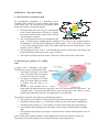
3. Overview of the mission
The mission has three stages:
(i) The satellite will first be placed
into an initial orbit around the earth
(see the figure).
(ii) The satellite will be permitted to
orbit the earth a few times to check
systems and to verify the orbit
(iii) At a pre-selected point on the
orbit, an onboard rocket will be fired
to place the satellite on a trajectory
to hit the moon. Your primary
mission is to determine the point at
which the rocket should be fired.
A commercially available launch vehicle (Ariane V) will be used to place the satellite into its initial orbit.
Full details of this launch facility can be found in the (huge) Ariane V user manual. Ariane V offers two
orbits: a Low Earth Orbit (LEO) which is not suitable for this mission, or a more suitable
Geosynchronous Transfer Orbit (GTO). Arianespace give details of the geometry of this orbit in their
manual, using the standard terminology for satellite orbits. This terminology is described briefly in
Appendix A, and the parameters for the orbit can be found in Section A5.
After launch, the satellite will be allowed to complete several orbits of the earth to give mission
controllers a chance to check on-board systems and verify that the satellite is in the correct orbit. It must
then use an on-board propulsion system to navigate to the moon and hit it.
Hitting the moon is complicated by the fact that the Ariane V GTO is not co-planar with the moon’s orbit.
A very powerful and expensive propulsion system is required to change the plane of a satellite’s orbit, so
it is preferable to attempt to hit the moon at one of the two special points where the moon’s orbit crosses
the satellite’s orbit plane.
The impact will be accomplished by firing a rocket that will increase the speed of the satellite, without
changing the direction of its velocity (this is the most efficient way to use a rocket). The increase in
speed places the satellite on a trajectory that can be chosen to impact the moon.
As the orbital designer for this mission, you have been charged with answering as many of the following
questions as possible:
1. Where are the two points where the lunar impact may take place?
2. What are the dates and times that the moon will be at the impact points?
3. What increase in satellite speed is required to hit the moon?
4. At what point on the GTO orbit should the rocket be fired?
5. How long does it take for the satellite to travel from the point where it leaves the GTO orbit to the
moon?
6. What is the resulting impact velocity with the moon?
All the necessary data to answer these questions is provided in this project description. In addition, a
detailed set of instructions for doing the calculations is given in the next section. In practice, of course,
you would need to decide what data you need, and then search for it; you would also have to work out for
yourself how to do the calculations.
4. Detailed project instructions
1. Read the appendix to familiarize yourself with the terminology that is used to describe satellite orbits.
In particular, make sure you are comfortable with the various coordinate systems used in
astrodynamic calculations.
2. Begin your calculations by writing a simple MATLAB script that will calculate the position vector of
the satellite as a function of time in the Ariane GTO orbit. The satellite orbit calculation done in class
should be helpful in doing this calculation – essentially you just need to extend this to 3D. For this
purpose
Neglect the gravitation of the moon
Assume that the earth is stationary
Draw a free body diagram and obtain an equation of motion for the satellite
Assume that at t=0 the satellite is at the perigee of the orbit with the correct initial velocity
vector. You can use the formulas in the Appendix to calculate the initial position and
velocity from the data in the table in the preceding section – don’t forget to include the radius
of the earth – the altitude specified by Arianespace refers to altitude above the earth’s
surface.
Write a MATLAB script that will integrate the equations of motion, given the initial
conditions. Make the code plot the 3D trajectory of the satellite.
Check your code by calculating and plotting the total energy and angular momentum of the
satellite as functions of time, and make sure they are (approximately) constant.
3. Extend your program to simulate the motion of the moon by itself (throughout this project, you should
just extend your code to do the new steps – there is no need to write separate scripts for all the
calculations). To do this, you will only need to call the ODE solver again with the appropriate initial
conditions for the moon (the equations of motion of the moon by itself are the same as those for the
satellite). Take the position vector and velocity vector of the moon at its perigee as the initial conditions.
You can calculate these using the procedure in Sect A5. Check your code by calculating the following:
The time for one complete orbit of the moon around the earth – you can check this against the
tabulated data.
The distance of the moon from the earth at its perigee and apogee.
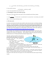
4. Note that the moon and the satellite do not
orbit the earth in the same plane. This makes
hitting the moon more difficult. In principle,
it is possible to change the plane of the
satellite’s orbit, but this requires a very large
and prohibitively expensive propulsion
system. It is better to try to hit the moon at
one of the two special points where the
moon’s orbit crosses the plane of the satellite
orbit. You can use your MATLAB code to
calculate the position vectors of these points.
For this purpose
Note that when the moon is in the
plane of the satellite’s orbit, its
position
vector
must
satisfy
rm n 0 , where n is a unit vector normal to the plane of the satellite’s orbit. The figure shows
why this is the case – at the special points, the angle between the position vector of the moon
and the normal is 90 degrees. A formula for a unit vector normal to the satellite orbit is given in
Section A2.
Add an `Event’ function to your MATLAB code to locate the points where rm n 0 . Your
‘event’ function could look something like this (but think about how you could modify the code
to identify the two impact points separately)
function [event_val,stopthecalc,direction] = detect_impact_point(t,w)
% Formula for unit vector normal to satellite orbit plane
n = enter your formula here
% Position vector of moon (this assumes w(1)=x,w(2)=y,w(3)=z)
r = w(1:3);
% Detect when r.n=0
event_val = dot(n,r);
stopthecalc = 0;
direction = 0;
end
Run the code to determine the position vectors of the two potential impact points. Also,
determine the dates and times that the moon will be in the correct position (of course, this will
occur at many times during successive orbits - you can create a table of possible impact dates and
times to help mission management). You should extract the time and location of the event from
the ODE solver as follows
options = code to define the ‘event’ function and tolerance
[t_vals,w_vals,tevent,wevent,indexevent] = ode45(etc, etc)
The variable ‘tevent’ will contain the time that the moon crosses each impact point, and the variable
‘wevent’ will contain the solution variable at these times, while ‘indexevent’ identifies the type of each
event ( indexevent(i)=1 for each value of i for the example above, as there is only one type of event).
Create a plot that shows the satellite orbit and the lunar orbit on the same picture, and shows the two
potential impact points. Neglect the effects of the moon’s gravity on the satellite. To do this:
Solve the equation of motion for the satellite (with appropriate initial conditions) and plot it with
figure
hold on
plot3(w_vals(:,1),w_vals(:,2),w_vals(:,3))
Solve the equation of motion for the moon (with the appropriate initial conditions) and plot it
with
Add the position of the moon at one of the impact points with, e.g.
plot3(w_vals(:,1),w_vals(:,2),w_vals(:,3))
rmoon = wevent(1,1:3);
plot3(rmoon(1),rmoon(2),rmoon(3),'ro','MarkerSize',11,'MarkerFaceColor','r')
and similarly for the second point. It is helpful to color the two impact points differently, so you
can distinguish them. It will also help you in later calculations if you can work out the direction
of motion of the moon as it passes through each impact point.
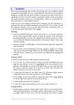
5. The satellite will be launched on a trajectory to
hit the moon by firing a rocket at some point around
its orbit. The rocket fires very quickly (over a few
minutes), so its effect can simply be idealized as an
impulse which changes the velocity of the satellite.
The propulsion system will be used to simply
increase the satellite’s speed by some unknown
amount V , without changing its direction of
motion. The change in velocity required to hit the
moon must be calculated. For later calculations, we
must also determine how long it takes for the
satellite to reach the impact point.
To do this, we will model the motion of the satellite as it moves from a pre-selected point on the GTO
orbit towards the impact point.
To begin with, assume that the rocket is fired at the perigee of the satellite orbit. This means that you
know (a) the position vector and (b) the velocity of the satellite at the time the rocket is fired. You can
use these as initial conditions in your MATLAB code to calculate the subsequent trajectory of the
satellite. You don’t need to account for the gravity of the moon in this calculation, or to consider the
motion of the moon – the goal is simply to get the satellite from the perigee to the impact point.
It is helpful to start this calculation by creating a function that will (a) plot the trajectory of the satellite as
it travels towards the moon, and (b) calculate the closest approach distance of the satellite to the impact
location as a function of the initial position and velocity of the satellite and the increase in velocity V .
Your function (which should be inside your main project function) could look something like this
%
This evaluates the function with delta_V=0.5 km/sec just to test it out
[test_distance,test_time] = mindisttomoon(0.5,r0,v0,r_impact)
function [d,time_to_reach_min_point] = mindisttomoon(delta_V,r0,v0,r_impact)
%
Function to calculate min distance to moon for satellite
%
trajectory. r0 and v0 are the position and velocity of the
%
satellite just before the rocket is fired, and delta_V is the increase
%
in its velocity, in km/sec, while r_impact is the position vector of the
% impact point (computed in part 4)
%
time = 8*24*60*60.; % 8 days is enough to reach the moon
w0(1:3) = r0; % Initial position of satellite
w0(4:6) = v0 + delta_V*v0/sqrt(dot(v0,v0)); % Initial velocity
rtol = 0.00000001;
options = odeset('RelTol',rtol,'Events',@min_dist);
% Run the simulation to calculate the trajectory of the satellite
[t_vals,w_vals,tevent,wevent,ievent] = ode45(@eom,[0,time],w0,options);
% Plot the trajectory of the satellite on its way to the moon.
hold on
plot3(w_vals(:,1),w_vals(:,2),w_vals(:,3))
% Find distance to impact point at the event
% (r_impact is the position vector of the impact point – computed in 4)
rmin = wevent(1,1:3)-r_impact;
d = sqrt(dot(rmin,rmin)); % min dist to moon.
time_to_reach_min_point = tevent(1); % Time to reach the min dist.
end
Here @eom is the equation of motion for the satellite, which you coded in step (3). The `Event’ function
called @min_dist (which you must write, and which must be nested inside the mindisttomoon function)
should identify the point where the trajectory is closest to the impact point. This is a bit tricky, because
you need to find a way to use compute a value for the ‘event_value’ variable in the event function that
goes to zero at the point where the satellite passes closes to the moon. Note that at this special point the
position and velocity of the satellite must satisfy
r rimpact v 0
where rimpact is the position vector of the impact point, as calculated in step (4); r is the position vector
of the satellite, and v is the velocity of the satellite. You can use r rimpact v as your event_value
variable. Note that you can only hit one of the two candidate impact points from perigee. The moon
should be ‘descending’ (i.e. crossing the equatorial plane from North to South) at the correct impact point.
You will find it extremely helpful to test this function by plotting the trajectory of the satellite on its way
to the impact point, for several different values of delta_V (try values between 0.4 and 1). Plot the
trajectory on top of the plot of the moon orbit and impact points that you completed in step 4. If the
satellite does not look as though it passes very close to one of the impact points for some choice of
delta_V, something is wrong, and it’s not worth continuing until you fix it. The most likely error is that
you have made a mistake in calculating the initial conditions for the moon or the satellite. Also, while
testing this function, you might get an error saying that wevent(1,1:3) is undefined (or something like
that). This happens if MATLAB was unable to detect an event – i.e. there was no point where the
satellite got close to the impact point – if this happens, MATLAB does not assign a value to wevent, and
when you try to use the variable it gives the error. If this happens, use one of the handy swear-words
from the appendix. Then, simply comment out the last 3 lines of the function above, add two lines that
say d = 1234; time_to_reach_min_point = 4321; (or substitute your favorite numbers) and
look at your predicted trajectories to find out what went wrong.
Once your function plots sensible trajectories, the critical value of delta_V required to hit the moon can be
found by plotting the minimum distance as a function of delta_V, and identifying the point where the
distance is minimum on your graph (or by finding the min in your code) – this is sufficiently accurate for
design purposes. You will also need to calculate the time taken to reach the impact point. You can do this
using a simple loop (which must be outside your mindisttomoon function):
for i = 1:41 % (You can use more than 41 points if you like)
delta_V(i) = enter formula here to vary delta V from 0.4 to 1 km/s
[dist(i),traveltime(i)] = mindisttomoon(delta_V(i),r0,v0,r_impact);
end
plot(dist,delta_V);
[distmin,index] = min(dist); % Find the min value in the vector dist
critical_delta_V_perigee = delta_V(index) %Print the magic delta V
figure
plot(delta_V,traveltime);
time_to_hit_from_perigee = traveltime(index) %Print the travel time
You will probably find that delta_V lies somewhere in the range 0.4<delta_V<1 km/s.
6. Repeat step (5), but this time start the satellite from the apogee of its orbit, and try to hit the second
(‘ascending’) impact point. For this purpose you will need to find the position and velocity vectors of the
apogee of the satellite orbit. This should be done by hand, using conservation of angular momentum or
energy, and some elementary geometry. For this case, you can assume that delta_V lies somewhere in the
range 1<delta_V<3 km/s. Note that you don’t need to write another minimum distance function for this
calculation – all you need to do is to change the values of r0,v0,r_impact.
7. Finally, you should calculate the impact velocity with the moon more accurately. For this purpose, you
will need to modify your script to account for the effects of the moon’s gravity on the motion of the
satellite (it is not necessary to account for the effects of the satellite on the moon). This means you must
solve for the motion of the moon and the satellite at the same time.
(a) Derive equations of motion for the moon and the satellite – choose a coordinate system, draw a
FBD, and use Newton’s laws. Introduce the velocity of the satellite and moon as additional
unknowns to write the equations of motion into the standard form required by MATLAB (there
will be a total of 12 unknowns). Don’t forget that the moon’s gravity is weaker than the earth’s.
(b) Extend your MATLAB program to solve the new equations of motion.
(c) Next, you will need to determine initial conditions for this simulation. The satellite will start
from GTO perigee, and its initial velocity can be computed using the results of step 5. You must
also determine the initial position and velocity of the moon. To find this, find (i) the time t1 taken
for the moon takes to travel from perigee to the impact location (already determined in step 4);
(ii) the time t2 taken for the satellite to travel from the appropriate point on the GTO orbit to the
impact location (determined in step 5). Then, (using your code that simulates the moon by itself)
start the moon from its perigee at t=0, and compute the position and velocity vectors at time
t1 t2 . The position and velocity of the moon at the end of this computation will be the initial
conditions for the impact simulation.
(d) Write an `event’ function that will detect the time when the satellite hits the surface of the moon.
(e) Run the code that simulates the satellite and moon together, using initial conditions computed in
step (c), and hence calculate the impact velocity (i.e. the magnitude of the difference between the
velocity of the moon and the satellite at the instant of impact).
Note that everything has to work correctly for you to be able to impact the moon. To debug, you will
find it helpful to animate the motion of the moon and satellite. The following script will animate a
trajectory, assumed to be stored in a variable called ws, with time values in times
for i=1:length(times)
clf
% Clear the frame
plot3(ws(:,1),ws(:,2),ws(:,3)) %Plot the entire trajectory
hold on
plot3(ws(i,1),ws(i,2),ws(i,3),’ro’,’MarkerSize’,10’,’MarkerFaceColor’,’r’)
pause(0.05)
end
You can modify this appropriately to show both the moon and the satellite.
6. Report instructions
PRELIMINARY REPORT: Your preliminary report, due Friday March 12th, should consist of solutions
to parts 1-3 of section 4. It should include:
Free body diagrams for the satellite (or the moon) orbiting the earth
A derivation of the equation of motion for the satellite (or moon) orbiting the earth.
MATLAB code that will simulate the motion of the satellite or moon around the earth.
A graph of the total energy of the satellite as a function of time as the satellite completes at least 1
full orbit; and a second graph of the total angular momentum of the satellite as a function of time
for the same period of time.
The predicted time for one complete orbit of the moon around the earth, and a comparison of your
prediction with the value determined from the lunar tables
The predicted distance of the moon from the earth at its perigee and apogee, and a comparison
with the values determined from the table.
FINAL REPORT: Your report should be a formal presentation of your recommendations to
management. The main purpose of the report is to communicate clearly your findings. A secondary
purpose is to present enough details about your calculations that another engineer could check and repeat
them.
Here is a possible outline for the report:
1. Abstract - a short summary of the content of the report. In this project the conclusions are simple
enough that you can report them in the abstract if you wish, but that is often not possible.
2. Introduction – give a brief description of the mission, explain the role of the report in mission
planning, outline the information contained in the report and summarize the main conclusions
3. Mission calculations – this section should contain several sub-sections that describe how you
have addressed the questions listed in Section 3. In each case it is important to list any
assumptions made in doing the calculations, outline briefly how the calculations were done, and
present the results of the calculations.
4. Conclusions – this should clearly and concisely summarize your recommendations, giving any
quantitative information that you think is necessary for mission management.
5. References
6. Appendix – here you can go nuts and include all the gory details of your calculations, including
MATLAB scripts, if you wish.
It is best not to make your report a blow-by-blow account of each individual calculation you did, in the
order that you did them. In fact, some calculations (which you just ran to check your code) need not be
reported at all. The purpose of your report is so that the reader can understand (1) why your results are
important; (2) What your conclusions are; and (3) The reasoning (or calculations) that led to your
conclusions. The introduction should address (1); the mission calculations sections should address (3);
and the conclusions should address (2).
It is not easy to write good reports. Often, more effort goes into writing a report than the calculations
themselves – writing style, grammar, presentation and organization are all important. If you get really
good at report writing it will give your future career a huge boost. Fortunately Brown is one of the best
places in the world to learn how to write well…
7. Final report grading rubric
Grades will be based on the content of the final report, as follows:
1. Abstract: appropriate length; accurately describes content of report; clearly written (5 points)
2. Introduction: Includes appropriate background information; explains purpose of report; gives
outline of remainder of report; clearly written in good English. 5 points
3. Mission calculations: Calculations done correctly; report organized so that important results
can be found easily; includes brief but clear description of how results were calculated; and
correctly states results of calculations; clearly written in good English - 10 points
4. Conclusions: Concise summary of results of calculations. 5 points
5. References – appropriate selection of source material properly cited 3 points
6. Appendix: Calculations all done correctly. Calculations and MATLAB code described in
sufficient detail that calculations can be checked and repeated. Organized in a logical
manner. 17 points
7. Presentation – report layout; typing, quality of figures and tables; 5 points
Total 50 Points
THE COVER PAGE OF YOUR REPORT MUST CONTAIN THE FOLLOWING STATEMENT:
This report has been prepared in accordance with the honor code of Brown University.
The report and MATLAB code are my own work.
8. References
Ariane V Users Manual http://www.arianespace.com/launch-services-ariane5/Ariane-5-User'sManual.asp (very large file - 23MB)
Lunar orbit parameters http://www.usno.navy.mil/USNO/astronomical-applications/data-services/geo-pos
Ejecta plume simulations for Deep Impact mission http://www.astro.cornell.edu/~richardson/ejector.html
NASA ‘Deep Impact’ web site http://www.nasa.gov/mission_pages/deepimpact/main/index.html
NASA LCROSS web site http://lcross.arc.nasa.gov/
APPENDIX A – Data and Formulas
A.1 The Geocentric Coordinate System
For astrodynamical calculations, it is important to use a
coordinate frame which has a fixed orientation with respect
to the nearby stars. By convention, the coordinate system
shown in the figure is used for this purpose.
We choose three unit vectors i, j, k , with k parallel
to the Celestial North pole of the earth (i.e. parallel
to its axis of rotation); and i parallel to the so-called
`Vernal Equinox’ direction.
The Vernal Equinox direction (i) is illustrated in the
figure. At each equinox, (roughly March 12 and Sept 21) the sun lies in the equatorial plane of
the Earth (that is why the day and night have the same length). The ‘Vernal equinox’ direction
is a unit vector pointing from the center of the earth towards the sun at the instant that the ‘Vernal
Equinox’ occurs (in March).
The remaining unit vector j k i . Note that the (i,j) vectors lie in the plane of the equator; and
that the earth rotates with respect to the i, j, k directions.
The origin for specifying position vectors is taken to be at the center of mass of the earth.
A.2 Specifying the geometry of a satellite
orbit
A generic orbit is illustrated in the figure.
The following are special points on the orbit:
1. The periapsis (or perigee, for an earth
orbit) is the point where the satellite
is closest to the object it is orbiting;
2. The apoapsis (or apogee, for an earth
orbit) is the point where the satellite
is furthest from the object it is
orbiting
3. The line of nodes connects the two
points where the orbit intersects the (i,j) plane. These two special points are called nodes – the
`ascending node’ is the point where the satellite crosses the (i,j) plane with a positive velocity
parallel to the k direction; while the `descending node’ is the other point.
The geometry of an orbit is described using the following numbers:
1. The inclination of the orbit ( ) is the angle between the plane of the orbit and the (i,j) plane,
2. The altitude of the periapsis ( rp ) is the distance from the surface of the planet to the periapsis;
3. The altitude of the apoapsis ( ra ) is the distance from the surface of the planet to the apoapsis
4. The longitude of the ascending node is the angle between the i direction and the ascending
node
5. The argument of the periapsis is the angle between the line of nodes and the position vector of
the periapsis.
A table of the values of these parameters for the ARIANE GTO orbit can be found in Section A5.
The position vector of the periapsis can be calculated in terms of these quantities as
r p rp cos cos sin sin cos i cos sin sin cos cos j sin sin k
It is also useful to note that
n sin sin i cos sin j cos k
is a unit vector perpendicular to the plane of the orbit.
A.3 Calculating the velocity of the satellite at perigee
The velocity vector of the satellite at the periapsis can be calculated from the following formula
1/2
ra
v p 2
sin cos cos sin cos i cos cos cos sin sin j cos sin k
rp (ra rp )
where GM is the gravitational parameter.
A.5 The Lunar orbit
It is tricky to describe the orbit of the moon around the earth, because the orbit is continuously changing
with time. For example, the moon’s orbital plane rotates Westward around the earth, completing a full
revolution in 18.6 years. Similarly, the line of apsides (the line joining the perigee and the apogee of the
orbit) rotates with a period of 8.9 years. This behavior is due partly to the gravitational effects of the sun,
and partly because the earth is not perfectly spherical and homogeneous, so that it’s center of gravity is
not a fixed point. Mission planning relies on detailed tables of lunar positions, which can be found e.g. at
http://www.usno.navy.mil/USNO/astronomical-applications/data-services/geo-pos
To use the tables, select “Astrometric Geocentric Right Ascension and Declination” in the position menu,
and select “Moon” in the Celestial object box. Set the Tabular Interval to “hours” and set the number of
repetitions to 700. Then press “compute data.” This will produce a table giving the position of the moon
at hourly intervals over a 700 hour period (should include a complete orbit).
The tables specify the position of the moon by
giving two angles: the right ascension of the moon,
the declination, and the distance of the moon from
the center of the earth. These quantities are
illustrated in the figure.
1. The right ascension is specified in
hours minutes and seconds – 24 hrs
corresponds to 360 degrees
2. The declination is specified in degrees,
minutes and seconds. Note that declination may be negative (this means that degrees, minutes and
seconds are all negative) – be careful not to miss the negative sign.
3. The radial coordinate specifies the distance of the moon from the center of the earth.
For the moon, the angles are measured relative to the mean equator of the earth, and the angle is
measured relative to the Vernal Equinox direction.
HEALTH WARNING: it is critical to use these tables correctly – be particularly careful to identify the
apogee and perigee correctly, and to convert properly from degrees (or hours), minutes & seconds to
decimal – if you get the lunar orbit wrong, you won’t be able to hit the moon.
The position vector of the moon in the i, j, k basis can be calculated from these data using the following
formula
r cos cos i cos sin j sin k
You can also identify the apogee and perigee of the moon’s orbit from the data in the table. The velocity
vector of the moon at the perigee can be computed from
1/2
m rp
a
v p 2
p ( a p )
p
where r p is the position vector of the perigee, a , p are the radial coordinates of the apogee and
perigee, and m is a unit vector perpendicular to the plane of the orbit (the sign of m must be chosen so
that m k 0 - don’t forget this, or the moon ends up moving backwards).
You can find the perigee in the table of positions by locating the point where the moon is closest to the
earth. You can find a unit vector normal to the moon’s orbit by taking the cross product of the position
vectors of two different points on the orbit (make sure the two points are well separated, don’t forget to
convert the cross product into a unit vector, and be very careful to get the sign of the unit vector right- if
you get the sign wrong the moon orbits in the wrong direction and you won’t be able to hit it.). DO NOT
USE BOTH THE APOGEE AND PERIGEE FOR THE POINTS THAT DETERMINE THE
NORMAL TO THE ORBIT (can you see why?)
A6. Useful data
Mean equatorial radius of the earth 6378.145km
Mean equatorial radius of the moon 1737.4km
Gravitational parameter GM 3.986012 105 km3s 1 (G= gravitational constant;
M=mass of earth)
Ratio of moon’s mass to earth’s mass 0.012298
Orbit parameters for Ariane V GTO
Inclination
7 degrees
Altitude of perigee
250 km
Altitude of apogee
35950 km
Argument of perigee
178 degrees
Longitude of first ascending node 180 degrees
A6. List of geeky astronomical terms (to impress your friends)
Apoapsis – the point on an orbit at which a satellite is furthest from the body it is orbiting
Apogee – the Apoapsis for a satellite orbiting the earth
Apohelion – the apoapsis for a satellite orbiting the sun
GTO – Geosynchronous Transfer Orbit
LEO – Low Earth Orbit
Periapsis – the point on an orbit at which a satellite is closest to the body it is orbiting
Perigee – the periapsis for a satellite orbiting the earth
Perihelion – the periapsis for a satellite orbiting the sun
A7. A few useful swear words.
Bazdmeg ! (Hungarian) Dritt! (Norwegian) Paska! (Finnish) Do kurwy nędzy! (Polish) Cach! (Welsh)
Drek! (Slovenian) me cago en la hostia! (Spanish)