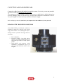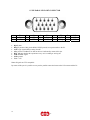
1
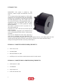
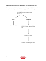
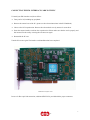
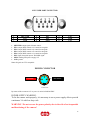
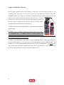
DISCOVERY
User Manual
December 2005
s.r.l.
Copyright 2005 DTA s.r.l.
All rights reserved. The reproduction of any part of this manual is allowed only with the written
authorization by DTA s.r.l..
The contents of this manual may be subject to changes without any warning.
DTA are not responsible for errors that may occur in this manual.
Revision 1.1 dated 30/12/2005
2
s.r.l.
CONTENTS
INTRODUCTION
PERSONAL COMPUTER MINIMUM REQUIREMENTS
PERSONAL COMPUTER RECOMMENDED REQUIREMENTS
SCHEME OF THE INSTALLATION PROCEDURE (case with EPP port)
SCHEME OF THE INSTALLATION PROCEDURE (case with FDL Interface card)
CONNECTING THE FDL INTERFACE CARD TO THE PC
LIBRARY & FDL-PCI INSTALLATION
WINDOWS XP
LINUX
WINDRIVER REGISTRATION
CONNECTING CABLES AND POWER LEADS
DETAIL OF DISCOVERY CONNECTORS
15-PIN PARALLEL PORT CONNECTOR
9-PIN USER PORT CONNECTOR
POWER CONNECTOR
OPTICAL WINDOW CLEANING
SPECIFICATIONS
INDEX
4
4
4
5
6
7
8
12
14
17
17
18
19
19
20
21
22
3
s.r.l.
INTRODUCTION
DISCOVERY CCD camera is marked by high
sensitivity, reduced weight and dimensions and low
costs.
As it is characterised by high integration, it offers quality
performances like a professional CCD: fast downloading
of image (up to 100 Kpixel/s with bidirectional parallel
port) and a high dynamic range. This is thanks to the use
of a 14 bit A/D Converter with programmable CDS at 64
amplification gains with changeable offset. The latter
characteristic enables us to better optimise the binning
function modalities.
The camera is connected to the PC by means of a bidirectional parallel port.
Powered at 10-15 volt it can also be used in the open air
using a car battery.
Every component is integrated in the aluminium head:
CCD, electromechanical shutter, Peltier cooling system,
electronics.
This series uses Kodak KAF CCD sensors, displaying a
wide range of resolutions and pixels dimensions. The
sensors are front-illuminated, supported by an excellent quantum efficiency. All of them (apart from those
with the anti-blooming option) can offer a 100% fill factor, allowing one to shoot marvellous images!
Among the main application fields: Astronomy, Plasma Physics.
PERSONAL COMPUTER MINIMUM REQUIREMENTS
•
CPU Celeron 1 Ghz .
•
256 Mb di RAM.
•
Microsoft Windows 98, ME.
•
An EPP port to be used for the connection between the PC and the camera.
PERSONAL COMPUTER RECOMMENDED REQUIREMENTS
•
CPU Pentium IV 2 GHz
•
512 Mb RAM.
•
Colour monitor 19”.
•
A FDL-PCI interface card
4
s.r.l.
SCHEME OF THE INSTALLATION PROCEDURE (case with EPP port)
When you use the camera for the first time, you must install the DTA software. Insert the SDK CD, provided
with the camera, into the CD-ROM reader, wait a few seconds so as to allow the PC to load the "QUICK
INSTALL" menu.
Let disable the Register FDL-PCI Driver function, not necessary in this case and click on ViSTA to install
the software necessary for the camera management.
Once you have installed it, restart the PC.
5
s.r.l.
SCHEME OF THE INSTALLATION PROCEDURE (case with FDL Interface card)
When you use the camera for the first time, you must install the library and the FDL-PCI interface. For this
purpose, please follow the procedure described in the next pages and schematized in the diagram below:
Turn the PC off
Insert the FDL-PCI interface in the proper SLOT
Turn the PC on
LINUX
Let install the DRIVER
WINDOWS
WINDOWS OS ask to you the DRIVER:
specify the directory within the provided
CD.
Let install ViSTA software
Verify the configuration of the camera
with CAMERA SELECT option
6
s.r.l.
CONNECTING THE FDL INTERFACE CARD TO THE PC
To install your FDL interface card, do as follow :
⇒ Turn your PC off, including any peripheral.
⇒ Remove the external case of the PC ( please see the relevant instructions in the PC Handbook).
⇒ Choose a free PCI expansion slot. Remove the relevant back cover by means of a screwdriver.
⇒ Insert the camera interface card into the expansion slot. Please make sure that the card is properly and
fast inserted. Fix the card by screwing the relevant screw again.
⇒ Reassemble the PC case.
Turn the PC on once again. The interface card installation has been completed.
FDL-PCI interface card
In case of a fiber optic link connection, a dedicated FDL-PCI is provided with the proper connectors.
7
s.r.l.
LIBRARY & FDL-PCI INSTALLATION
The installation of the library is always linked to the installation of the camera, of course. For this purpose
you just need to install the PCI interface as well.
Let’s analyse the sequence of operations to be carried out. It will be shown the example with WINDOWS XP
Operating System. The operation are similar for the other Operating Systems.
Once you turn the system on for the first time with the FDL-PCI interface on, you will be asked to specify
where the available drivers are. Follow the steps on the basis of your Operative System.
WINDOWS XP
1) Insert the FDL-PCI card into the slot of the motherboard and turn the PC on. As soon as the system
gets started, a window (like the one shown below) will appear, noticing you a new hardware was
found. You’ll be requested to connect for Windows update, let select: “No, not at this time”.
8
s.r.l.
2) Insert the "ViSTA" CD into the CD-ROM reader, close the "Quick Install" (it may open due to the
CD autorun). Select the option "Install from a list or specific location (Advanced)” (recommended
choice). Then click on "Next" to continue the installation.
3) Check the function selected in the window (recommended choice) below (in this case, E:\ indicates
the CD-ROM drive) and click on next to continue. The PC will start to search for the most suitable
driver to the peripheral.
9
s.r.l.
4) Select the folder that contains drivers for FDL-PCI hardware and click on OK. Then, wait while the
wizard installs the software (just few seconds).
10
s.r.l.
5) When the installation has been completed, a window like the one below will appear.
Click on finish to close the wizard and restart the PC (recommended choice).
11
s.r.l.
LINUX
System Requirements
•
•
•
Linux 2.0.31 or higher (can be embedded Linux or Linux 2.4x)
An x86 processor.
Any 32-bit development environment supporting C (such as GCC).
Preparing the system for installation
In Linux, kernel modules must be compiled with the same header files that the kernel itself was compiled
with. Since WinDriver installs the kernel module windrvr6.o, it must compile with the header files of the
Linux kernel during the installation process.
Therefore, before you install WinDriver for Linux, verify that the Linux source code and the file versions.h
are installed on your machine:
Install linux kernel source code
•
•
If you have yet to install Linux, please choose Custom installation when performing the installation
and then choose to install the source code.
If Linux is already installed on the machine, you must check to see if the Linux source code was
installed. You can do this by looking for linux in the /usr/src directory. If the source code is not
installed, you can either reinstall Linux with the source code, as described above, or you can install
the source code by following these steps:
1. Login as super user.
2. Type:
/$ rpm -i /<source location>/ <Linux distributor>/RPMS/kernel-source-<version
number>
(For example: to install the source code from the Linux installation CD-ROM, for RedHat
7.1, type:
/$ rpm -i /mnt/cdrom/RedHat/RPMS/
kernel-source-2.4.2.-2.i386rpm)
TIP!
If you do not have an RPM with the source code, you may download it from:
http://rpmfind.net/linux/RPM/.
Install version.h
•
The file version.h is created when you first compile the Linux kernel source code. Some
distributions provide a compiled kernel without the file version.h. Look under
/usr/src/linux/include/linux/ to see if you have this file. If you do not, please follow these steps:
1. Type:
/$ make xconfig
2. Save the configuration by choosing Save and Exit.
3. Type:
/$ make dep.
Before proceeding with the installation, you must also make sure that you have a linux symbolic link. If you
do not, please create one by typing:
/usr/src$ ln -s <target kernel>/ linux
(For example: for Linux 2.4 kernel type:
/usr/src$ ln -s linux-2.4/ linux)
12
s.r.l.
Installation
1.
2.
3.
4.
Insert the DTA SDK CD into your Linux machine CD drive or copy the downloaded file to your
preferred directory.
Change directory to your preferred installation directory (your home directory, for example):
/$ cd ~
Extract the file WDxxxLN.tgz (where xxx is the version number):
~$ tar xvzf /<file location>/WDxxxLN.tgz
For example:
o From a CD:
~$ tar xvzf /mnt/cdrom/LINUX/WDxxxLN.tgz
o From a downloaded file:
~$ tar xvzf /home/username/WDxxxLN.tgz
Change directory to WinDriver (this directory gets created by tar):
~$ cd WinDriver/
NOTE:
From version 5.x and above this directory gets created by tar, but in versions preceding 5.x the
WinDriver directory does not get created by the extraction. Therefore, when working with versions
preceding 5.x (version 4.33, for example) first create a directory (e.g., WinDriver) before proceeding
with the installation.
(/$ mkdir ~/WinDriver)
5.
6.
7.
8.
9.
Install WinDriver:
a. ~/WinDriver$ make
b. Become super user:
~/WinDriver$ su
c. Install the driver:
~/WinDriver# make install
Create a symbolic link so that you can easily launch the DriverWizard GUI
~/WinDriver$ ln -s ~/WinDriver/wizard/wdwizard/ usr/bin/wdwizard
Change the read and execute permissions on the file wdwizard so that ordinary users can access this
program.
Change the user and group ids and give read/write permissions to the device file /dev/windrvr6
depending on how you wish to allow users to access hardware through the device.
You can now start using WinDriver to access your hardware and generate your driver code!
Restricting Hardware Access on Linux
CAUTION:
Since /dev/windrvr6 gives direct hardware access to user programs, it may compromise kernel stability on
multi-user Linux systems. Please restrict access to the DriverWizard and the device file /dev/windrvr6 to
trusted users.
For security reasons the WinDriver installation script does not automatically perform the steps of changing
the permissions on /dev/windrvr6 and the DriverWizard executable (wdwizard).
13
s.r.l.
WINDRIVER REGISTRATION
1) After the installation of the drivers for the FDL-PCI card, we need to record the files to make them work
properly. Insert the "ViSTA 3" CD into the CD-ROM reader, wait a few seconds so as to allow the PC to
load the "QUICK INSTALL" menu.
2) Once the PC has loaded the "QUICK INSTALL" menu, enable the function “Register FDL-PCI Driver”,
then click on "VISTA 3". The PC will start the installation of the necessary drivers by loading a window
like the one shown below.
14
s.r.l.
Once you have installed the drivers and the "ViSTA 3" software, restart the PC.
When you restart the PC, it is suggested to check the correct installation of the peripheral, that is if the
installation of the necessary drivers for the FDL-PCI card and WINDRIVER has been carried out good.
According to the different Operating Systems, you have to click on "System Properties" by means of the
right key of the mouse. The images below refer to the case you use Windows XP as OS.
A menu with different options will open; click on "Hardware" by means of the left key of the mouse and on
"Device Manager". Then check if the FDL-PCI peripheral has been installed correctly (see the images
below).
15
s.r.l.
The tests have been carried out with the following OS:
WINDOWS 98 SECOND EDITION
WINDOWS 2000 WITHOUT SERVICE PACK
WINDOWS 2000 WITH SERVICE PACK 3/4/5
WINDOWS ME
WINDOWS XP WITHOUT SERVICE PACK
WINDOWS XP WITH SERVICE PACK 1/2
16
s.r.l.
CONNECTING CABLES AND POWER LEADS
Connect the cables between the parallel port and the camera. We advise you to carry out this
operation with all your instruments not powered !
The connectors are fixed by means of screws; those, however, should only be slightly tightened to
avoid any damage to them. For the Discovery series the power connector is connected to a 10-15V
3A power supply. The camera is always turned on at the power supply.
Before making any connection, make sure your computer is off and the Discovery is not powered !
DETAILS OF THE DISCOVERY CONNECTORS
On the DISCOVERY you will find the connectrors
required to connect it to the PC, to the power
supply and to mount it on to a photographic tripod.
Starting from the top left the following connectros
are shown :
•
•
•
Power connectror;
PARALLEL PORT: 15-pin high density
connector for parallel communication 8 bit
with the PC by means of a simple printer
parallel.
USER PORT: 9-pin connector which
implements a communication port, to be
used to run the RPF6 filter wheel or the
autoguide.
17
s.r.l.
15 PIN PARALLEL PORT CONNECTOR
1
6
11
•
•
•
•
•
•
•
•
D1
D4
ACK
2
7
12
D0
D7
STB
3
8
13
D3
D6
VCC
4
9
14
D2
R/W
REQ
5
10
15
D5
A/D
GND
D[0:7]: data.
REQ: by means of this pin the DISCOVERY proceeds to request transfer to the PC.
ACK: reply signal to REQ coming from PC.
A/D: presence of addresses or data on the bus is indicated by means of this pin.
R/W: indicates whether the operation to carry out is a reading or writing one.
STB: STROBE signal.
GND: ground.
VCC: +12V.
Note: all signals are TTL compatible.
By means of this port it is possible to carry out the parallel connection between the CCD camera and the PC.
18
s.r.l.
9 PIN USER PORT CONNECTOR
1
4
7
•
•
•
•
•
•
•
•
SHUTTER
EX3
GND
2
5
8
EX1
EX4
GND
3
6
9
EX2
PWR
EXI
SHUTTER: output signal of shutter control.
EX1: (output) RPF6 control or N control for autoguide.
EX2: (output) RPF6 control or S control for autoguide.
EX3: (output) RPF6 control or E control for autoguide.
EX4: (output) RPF6 control or O control for autoguide.
EXI: (input) autoguide input or TRIGGER signal.
PWR: Warning main power supply, 12V
GND: ground.
Note: all signals are TTL compatible.
POWER CONNECTOR
POSITIVE +
NEGATIVE -
Front View
By means of this connector 12V 3A power is carried to DISCOVERY.
POWER SUPPLY WARNING:
To let the camera work properly, it is necessary to use a power supply able to provide
continuous 3A with low duty-cicle.
WARNING ! Do not reverse the power polarity due to the risk of an irreparable
malfunctioning of the camera !
19
s.r.l.
OPTICAL WINDOW CLEANING
Both the optical window and the CCD cleaning are carried out in the clean room by means of a 30magnifying power microscope. This procedure removes any dust which can otherwise bring about
unmistakable marks on the image you have taken. In particular such spots increase as the focal ratio gets
wider. In other words an image may not show any mark at f/5.6 but
it can be
clearly noted at f/32 because of an obvious geometrical problem of projection.
Due to the shutter or elapsed time, the external surface of the optical window
may gather dirty particles that may be easily removed.
To perform such task we use a compressed air cylinder specifically designed for
optical cleaning.
Be careful !!! There are similar products that, instead of using compressed air,
use a liquefiable gas : at ambient pressure it quickly gassifies, thus
“triggering” an air-compressed-effect. You do not absolutely have to use these products : they may give rise
to heavy marks or rings on the windows itself.
A product we can recommend is DUST-OFF provided by EDMUND-OPTICS. Thanks to DUST-OFF (or
any other similar product) it is very easy to get rid of any microparticles : keep the shutter open for a few
seconds (by the camera control program) and spray some air blast. We kindly advise you against using
cloths, optical paper and cleaning liquids because the dirt will be only mixed up or, even worse, increased.
The risk is to finally damage the coating of the optical window itself !
20
s.r.l.
SPECIFICATIONS
SHUTTER:
Electromechanical. Exposure time: from 0.1 s to 9999 s
A/D CONVERTER:
14 bit
SETTABLE GAINS:
64
READ OUT SPEED:
up to 100 kpixel/s
INTERFACE:
Parallel Port (EPP)
FDL-PCI: 16 bit (optional)
COOLING:
Single stage PELTIER (-40°C below ambient)
CCD TEMPERATURE CONTROL:
± 0.1 °C
OPTICAL WINDOW:
BK7 with double AR coating
FILTER WHEEL:
External (optional)
BACKFOCUS:
17.5 mm
MAX TOTAL NOISE:
10 eMOUNT:
C
BINNING:
From 1 x 1 to 8 x 8 or arbitrary
POWER SUPPLY:
230V (optional, not included)
MAX ABSORPTION:
36 W
WEIGHT:
800 g
DIMENSIONS:
118 mm (Φ) x 53 mm (h)
21
s.r.l.
INDEX
9
9-PIN USER PORT CONNECTOR
19
15
15-PIN PARALLEL PORT CONNECTOR
19
C
CONNECTING CABLES AND POWER LEADS
CONNECTING THE FDL INTERFACE CARD TO THE PC
17
7
D
DETAIL OF DISCOVERY CONNECTORS
17
I
INTRODUCTION
4
L
LIBRARY & FDL-PCI INSTALLATION
LINUX
8
12
O
OPTICAL WINDOW CLEANING
20
P
PERSONAL COMPUTER MINIMUM REQUIREMENTS
PERSONAL COMPUTER RECOMMENDED REQUIREMENTS
POWER CONNECTOR
4
4
19
S
SCHEME OF THE INSTALLATION PROCEDURE (case with EPP port)
SCHEME OF THE INSTALLATION PROCEDURE (case with FDL Interface card)
SPECIFICATIONS
5
6
21
W
WINDOWS XP
WINDRIVER REGISTRATION
8
14
22
s.r.l.
23
s.r.l.
s.r.l.
Viale Campania 23
56021 Cascina (Pisa) - ITALY
web site: www.dta.it e-mail: [email protected]
24