1
Artisan Technology Group is your source for quality new and certified-used/pre-owned equipment • FAST SHIPPING AND DELIVERY • TENS OF THOUSANDS OF IN-STOCK ITEMS • EQUIPMENT DEMOS • HUNDREDS OF MANUFACTURERS SUPPORTED • LEASING/MONTHLY RENTALS • ITAR CERTIFIED SECURE ASSET SOLUTIONS SERVICE CENTER REPAIRS Experienced engineers and technicians on staff at our full-service, in-house repair center WE BUY USED EQUIPMENT Sell your excess, underutilized, and idle used equipment We also offer credit for buy-backs and trade-ins www.artisantg.com/WeBuyEquipment InstraView REMOTE INSPECTION LOOKING FOR MORE INFORMATION? Visit us on the web at www.artisantg.com for more information on price quotations, drivers, technical specifications, manuals, and documentation SM Remotely inspect equipment before purchasing with our interactive website at www.instraview.com Contact us: (888) 88-SOURCE | [email protected] | www.artisantg.com KPCI-PIO96 Parallel Digital I/O Board User’s Manual A GREATER MEASURE OF CONFIDENCE Artisan Technology Group - Quality Instrumentation ... Guaranteed | (888) 88-SOURCE | www.artisantg.com WARRANTY Hardware Keithley Instruments, Inc. warrants that, for a period of three (3) years from the date of shipment, the Keithley Hardware product will be free from defects in materials or workmanship. This warranty will be honored provided the defect has not been caused by use of the Keithley Hardware not in accordance with the instructions for the product. This warranty shall be null and void upon: (1) any modification of Keithley Hardware that is made by other than Keithley and not approved in writing by Keithley or (2) operation of the Keithley Hardware outside of the environmental specifications therefore. Upon receiving notification of a defect in the Keithley Hardware during the warranty period, Keithley will, at its option, either repair or replace such Keithley Hardware. During the first ninety days of the warranty period, Keithley will, at its option, supply the necessary on site labor to return the product to the condition prior to the notification of a defect. Failure to notify Keithley of a defect during the warranty shall relieve Keithley of its obligations and liabilities under this warranty. Other Hardware The portion of the product that is not manufactured by Keithley (Other Hardware) shall not be covered by this warranty, and Keithley shall have no duty of obligation to enforce any manufacturers' warranties on behalf of the customer. On those other manufacturers’ products that Keithley purchases for resale, Keithley shall have no duty of obligation to enforce any manufacturers’ warranties on behalf of the customer. Software Keithley warrants that for a period of one (1) year from date of shipment, the Keithley produced portion of the software or firmware (Keithley Software) will conform in all material respects with the published specifications provided such Keithley Software is used on the product for which it is intended and otherwise in accordance with the instructions therefore. Keithley does not warrant that operation of the Keithley Software will be uninterrupted or error-free and/or that the Keithley Software will be adequate for the customer's intended application and/or use. This warranty shall be null and void upon any modification of the Keithley Software that is made by other than Keithley and not approved in writing by Keithley. If Keithley receives notification of a Keithley Software nonconformity that is covered by this warranty during the warranty period, Keithley will review the conditions described in such notice. Such notice must state the published specification(s) to which the Keithley Software fails to conform and the manner in which the Keithley Software fails to conform to such published specification(s) with sufficient specificity to permit Keithley to correct such nonconformity. If Keithley determines that the Keithley Software does not conform with the published specifications, Keithley will, at its option, provide either the programming services necessary to correct such nonconformity or develop a program change to bypass such nonconformity in the Keithley Software. Failure to notify Keithley of a nonconformity during the warranty shall relieve Keithley of its obligations and liabilities under this warranty. Other Software OEM software that is not produced by Keithley (Other Software) shall not be covered by this warranty, and Keithley shall have no duty or obligation to enforce any OEM's warranties on behalf of the customer. Other Items Keithley warrants the following items for 90 days from the date of shipment: probes, cables, rechargeable batteries, diskettes, and documentation. Items not Covered under Warranty This warranty does not apply to fuses, non-rechargeable batteries, damage from battery leakage, or problems arising from normal wear or failure to follow instructions. Limitation of Warranty This warranty does not apply to defects resulting from product modification made by Purchaser without Keithley's express written consent, or by misuse of any product or part. Disclaimer of Warranties EXCEPT FOR THE EXPRESS WARRANTIES ABOVE KEITHLEY DISCLAIMS ALL OTHER WARRANTIES, EXPRESS OR IMPLIED, INCLUDING WITHOUT LIMITATION, ALL IMPLIED WARRANTIES OF MERCHANTABILITY AND FITNESS FOR A PARTICULAR PURPOSE. KEITHLEY DISCLAIMS ALL WARRANTIES WITH RESPECT TO THE OTHER HARDWARE AND OTHER SOFTWARE. Limitation of Liability KEITHLEY INSTRUMENTS SHALL IN NO EVENT, REGARDLESS OF CAUSE, ASSUME RESPONSIBILITY FOR OR BE LIABLE FOR: (1) ECONOMICAL, INCIDENTAL, CONSEQUENTIAL, INDIRECT, SPECIAL, PUNITIVE OR EXEMPLARY DAMAGES, WHETHER CLAIMED UNDER CONTRACT, TORT OR ANY OTHER LEGAL THEORY, (2) LOSS OF OR DAMAGE TO THE CUSTOMER'S DATA OR PROGRAMMING, OR (3) PENALTIES OR PENALTY CLAUSES OF ANY DESCRIPTION OR INDEMNIFICATION OF THE CUSTOMER OR OTHERS FOR COSTS, DAMAGES, OR EXPENSES RELATED TO THE GOODS OR SERVICES PROVIDED UNDER THIS WARRANTY. Keithley Instruments, Inc. 28775 Aurora Road • Cleveland, Ohio 44139 • 440-248-0400 • Fax: 440-248-6168 1-888-KEITHLEY (534-8453) • www.keithley.com Sales Offices: BELGIUM: Bergensesteenweg 709 • B-1600 Sint-Pieters-Leeuw • 02-363 00 40 • Fax: 02/363 00 64 CHINA: Yuan Chen Xin Building, Room 705 • 12 Yumin Road, Dewai, Madian • Beijing 100029 • 8610-8225-1886 • Fax: 8610-8225-1892 FINLAND: Tietäjäntie 2 • 02130 Espoo • Phone: 09-54 75 08 10 • Fax: 09-25 10 51 00 FRANCE: 3, allée des Garays • 91127 Palaiseau Cédex • 01-64 53 20 20 • Fax: 01-60 11 77 26 GERMANY: Landsberger Strasse 65 • 82110 Germering • 089/84 93 07-40 • Fax: 089/84 93 07-34 GREAT BRITAIN: Unit 2 Commerce Park, Brunel Road • Theale • Berkshire RG7 4AB • 0118 929 7500 • Fax: 0118 929 7519 INDIA: 1/5 Eagles Street • Langford Town • Bangalore 560 025, INDIA • 080 212 8027 • Fax : 080 212 8005 ITALY: Viale San Gimignano, 38 • 20146 Milano • 02-48 39 16 01 • Fax: 02-48 30 22 74 JAPAN: New Pier Takeshiba North Tower 13F • 11-1, Kaigan 1-chome • Minato-ku, Tokyo 105-0022 • 81-3-5733-7555 • Fax: 81-3-5733-7556 KOREA: 2FL., URI Building • 2-14 Yangjae-Dong • Seocho-Gu, Seoul 137-888 • 82-2-574-7778 • Fax: 82-2-574-7838 NETHERLANDS: Postbus 559 • 4200 AN Gorinchem • 0183-635333 • Fax: 0183-630821 SWEDEN: c/o Regus Business Centre • Frosundaviks Allé 15, 4tr • 169 70 Solna • 08-509 04 679 • Fax: 08-655 26 10 TAIWAN: 1FL., 85 Po Ai Street • Hsinchu, Taiwan, R.O.C. • 886-3-572-9077• Fax: 886-3-572-9031 9/02 Artisan Technology Group - Quality Instrumentation ... Guaranteed | (888) 88-SOURCE | www.artisantg.com KPCI-PIO96 Parallel Digital I/O Board User’s Manual ©1998, Keithley Instruments, Inc. All rights reserved. Cleveland, Ohio, U.S.A. Third Printing, September 2002 Document Number: 98060 Rev. C Artisan Technology Group - Quality Instrumentation ... Guaranteed | (888) 88-SOURCE | www.artisantg.com Manual Print History The print history shown below lists the printing dates of all Revisions and Addenda created for this manual. The Revision Level letter increases alphabetically as the manual undergoes subsequent updates. Addenda, which are released between Revisions, contain important change information that the user should incorporate immediately into the manual. Addenda are numbered sequentially. When a new Revision is created, all Addenda associated with the previous Revision of the manual are incorporated into the new Revision of the manual. Each new Revision includes a revised copy of this print history page. Revision A (Document Number 98060) . . . . . . . . . . . . . . . . . . . . . . . . . . . . . . . . . . . . . . . . . . . . August 1998 Revision B (Document Number 98060) . . . . . . . . . . . . . . . . . . . . . . . . . . . . . . . . . . . . . . . . . September 1998 Revision C (Document Number 98060) . . . . . . . . . . . . . . . . . . . . . . . . . . . . . . . . . . . . . . . . . September 2002 All Keithley product names are trademarks or registered trademarks of Keithley Instruments, Inc. Other brand and product names are trademarks or registered trademarks of their respective holders. Artisan Technology Group - Quality Instrumentation ... Guaranteed | (888) 88-SOURCE | www.artisantg.com Safety Precautions The following safety precautions should be observed before using this product and any associated instrumentation. Although some instruments and accessories would normally be used with non-hazardous voltages, there are situations where hazardous conditions may be present. This product is intended for use by qualified personnel who recognize shock hazards and are familiar with the safety precautions required to avoid possible injury. Read and follow all installation, operation, and maintenance information carefully before using the product. Refer to the manual for complete product specifications. If the product is used in a manner not specified, the protection provided by the product may be impaired. The types of product users are: Responsible body is the individual or group responsible for the use and maintenance of equipment, for ensuring that the equipment is operated within its specifications and operating limits, and for ensuring that operators are adequately trained. Operators use the product for its intended function. They must be trained in electrical safety procedures and proper use of the instrument. They must be protected from electric shock and contact with hazardous live circuits. Maintenance personnel perform routine procedures on the product to keep it operating properly, for example, setting the line voltage or replacing consumable materials. Maintenance procedures are described in the manual. The procedures explicitly state if the operator may perform them. Otherwise, they should be performed only by service personnel. Service personnel are trained to work on live circuits, and perform safe installations and repairs of products. Only properly trained service personnel may perform installation and service procedures. Keithley products are designed for use with electrical signals that are rated Installation Category I and Installation Category II, as described in the International Electrotechnical Commission (IEC) Standard IEC 60664. Most measurement, control, and data I/O signals are Installation Category I and must not be directly connected to mains voltage or to voltage sources with high transient over-voltages. Installation Category II connections require protection for high transient over-voltages often associated with local AC mains connections. Assume all measurement, control, and data I/O connections are for connection to Category I sources unless otherwise marked or described in the Manual. Exercise extreme caution when a shock hazard is present. Lethal voltage may be present on cable connector jacks or test fixtures. The American National Standards Institute (ANSI) states that a shock hazard exists when voltage levels greater than 30V RMS, 42.4V peak, or 60VDC are present. A good safety practice is to expect that hazardous voltage is present in any unknown circuit before measuring. Operators of this product must be protected from electric shock at all times. The responsible body must ensure that operators are prevented access and/or insulated from every connection point. In some cases, connections must be exposed to potential human contact. Product operators in these circumstances must be trained to protect themselves from the risk of electric shock. If the circuit is capable of operating at or above 1000 volts, no conductive part of the circuit may be exposed. Do not connect switching cards directly to unlimited power circuits. They are intended to be used with impedance limited sources. NEVER connect switching cards directly to AC mains. When connecting sources to switching cards, install protective devices to limit fault current and voltage to the card. Before operating an instrument, make sure the line cord is connected to a properly grounded power receptacle. Inspect the connecting cables, test leads, and jumpers for possible wear, cracks, or breaks before each use. When installing equipment where access to the main power cord is restricted, such as rack mounting, a separate main input power disconnect device must be provided, in close proximity to the equipment and within easy reach of the operator. For maximum safety, do not touch the product, test cables, or any other instruments while power is applied to the circuit under test. ALWAYS remove power from the entire test system and discharge any capacitors before: connecting or disconnecting cables or jumpers, installing or removing switching cards, or making internal changes, such as installing or removing jumpers. Do not touch any object that could provide a current path to the common side of the circuit under test or power line (earth) ground. Always make measurements with dry hands while standing on a dry, insulated surface capable of withstanding the voltage being measured. The instrument and accessories must be used in accordance with its specifications and operating instructions or the safety of the equipment may be impaired. Do not exceed the maximum signal levels of the instruments and accessories, as defined in the specifications and operating information, and as shown on the instrument or test fixture panels, or switching card. When fuses are used in a product, replace with same type and rating for continued protection against fire hazard. Chassis connections must only be used as shield connections for measuring circuits, NOT as safety earth ground connections. If you are using a test fixture, keep the lid closed while power is applied to the device under test. Safe operation requires the use of a lid interlock. Artisan Technology Group - Quality Instrumentation ... Guaranteed | (888) 88-SOURCE | www.artisantg.com 5/02 If or is present, connect it to safety earth ground using the wire recommended in the user documentation. The ! symbol on an instrument indicates that the user should refer to the operating instructions located in the manual. The symbol on an instrument shows that it can source or measure 1000 volts or more, including the combined effect of normal and common mode voltages. Use standard safety precautions to avoid personal contact with these voltages. The WARNING heading in a manual explains dangers that might result in personal injury or death. Always read the associated information very carefully before performing the indicated procedure. The CAUTION heading in a manual explains hazards that could damage the instrument. Such damage may invalidate the warranty. Instrumentation and accessories shall not be connected to humans. Before performing any maintenance, disconnect the line cord and all test cables. To maintain protection from electric shock and fire, replacement components in mains circuits, including the power transformer, test leads, and input jacks, must be purchased from Keithley Instruments. Standard fuses, with applicable national safety approvals, may be used if the rating and type are the same. Other components that are not safety related may be purchased from other suppliers as long as they are equivalent to the original component. (Note that selected parts should be purchased only through Keithley Instruments to maintain accuracy and functionality of the product.) If you are unsure about the applicability of a replacement component, call a Keithley Instruments office for information. To clean an instrument, use a damp cloth or mild, water based cleaner. Clean the exterior of the instrument only. Do not apply cleaner directly to the instrument or allow liquids to enter or spill on the instrument. Products that consist of a circuit board with no case or chassis (e.g., data acquisition board for installation into a computer) should never require cleaning if handled according to instructions. If the board becomes contaminated and operation is affected, the board should be returned to the factory for proper cleaning/servicing. Artisan Technology Group - Quality Instrumentation ... Guaranteed | (888) 88-SOURCE | www.artisantg.com Table of Contents 1 Overview 2 General Description Specifications ....................................................................................................................................................... 2-2 Functional description.......................................................................................................................................... 2-2 Standard digital I/O emulation ........................................................................................................................ 2-2 Other I/O characteristics ................................................................................................................................. 2-3 Bus control ........................................................................................................................................................... 2-3 Software ............................................................................................................................................................... 2-3 3 Installation Installing the software .......................................................................................................................................... 3-2 Software options ............................................................................................................................................. 3-2 DriverLINX driver software for Windows 9X/NT/2K/XP............................................................................. 3-2 TestPoint .................................................................................................................................................... 3-3 LabVIEW ................................................................................................................................................... 3-3 Installing DriverLINX..................................................................................................................................... 3-3 Installing theTestPoint User Defined Object (UDO) ...................................................................................... 3-3 Unwrapping and inspecting the KPCI-PI096 board ............................................................................................ 3-4 Installing and connecting the KPCI-PIO96 board ............................................................................................... 3-4 Locating the I/O connection points on the board ............................................................................................ 3-5 Connecting I/O cables and interface accessories ............................................................................................ 3-6 Using locally fabricated cable assemblies.................................................................................................. 3-6 Using manufactured cables and accessories .............................................................................................. 3-7 Installing the board.......................................................................................................................................... 3-8 Connecting I/O cables to your external circuit .................................................................................................... 3-8 Monitoring contact closure at an input ........................................................................................................... 3-9 Eliminating contact bounce............................................................................................................................. 3-9 Boosting relay drive current.......................................................................................................................... 3-10 Using +5 VDC from the computer power supply ......................................................................................... 3-10 i Artisan Technology Group - Quality Instrumentation ... Guaranteed | (888) 88-SOURCE | www.artisantg.com 4 I/O Address Mapping General memory assignments...............................................................................................................................4-2 Control and data register memory assignments....................................................................................................4-2 Setting control and data registers .........................................................................................................................4-4 5 Troubleshooting Identifying symptoms and possible causes...........................................................................................................5-2 Systematic problem isolation ...............................................................................................................................5-3 General problem isolation procedure ..............................................................................................................5-3 I/O bit tests ......................................................................................................................................................5-9 I/O loop-back test .....................................................................................................................................5-10 Output set test ...........................................................................................................................................5-16 Technical support ...............................................................................................................................................5-22 Appendix A Specifications .....................................................................................................................................................A-1 Appendix B Glossary .............................................................................................................................................................. B-1 ii Artisan Technology Group - Quality Instrumentation ... Guaranteed | (888) 88-SOURCE | www.artisantg.com List of Illustrations 3 Installation Figure 3-1 Figure 3-2 Figure 3-3 Figure 3-4 Figure 3-5 Figure 3-6 Pin assignments for I/O connectors (J102 through J105) ............................................................................ 3-5 Connector locations and port group assignments ........................................................................................ 3-6 Using manufactured cables and accessories ................................................................................................ 3-8 Contact-closure monitoring at a KPCI-PIO96 board input system connections ....................................... 3-10 De-bounce circuit for an input of a KPCI-PIO96 board ............................................................................ 3-10 NPN transistor relay control for an output of a KPCI-PIO96 board.......................................................... 3-11 5 Troubleshooting Figure 5-1 Figure 5-2 Figure 5-3 Figure 5-4 Figure 5-5 Figure 5-6 Figure 5-7 Figure 5-8 Figure 5-9 Figure 5-10 Figure 5-11 Figure 5-12 Figure 5-13 Problem isolation flowchart ......................................................................................................................... 5-4 Mating connector wiring for loop-back test............................................................................................... 5-11 IO Control Panel example.......................................................................................................................... 5-13 Setting port input and output ‘Configure’ switches ................................................................................... 5-14 Port A ‘write/read’ switch setting .............................................................................................................. 5-14 Port A output settings, bit pattern .............................................................................................................. 5-15 Port A output settings, bit pattern2 ............................................................................................................ 5-15 Correct bit patterns when port A is set to bit pattern 2. ............................................................................. 5-16 PIO Control Panel example........................................................................................................................ 5-18 Setting port ‘Configure’ switches .............................................................................................................. 5-19 Port ‘write/read’ switch settings ................................................................................................................ 5-19 Port output settings, bit pattern 1 ............................................................................................................... 5-20 Port output settings, bit pattern 2 ............................................................................................................... 5-21 iii Artisan Technology Group - Quality Instrumentation ... Guaranteed | (888) 88-SOURCE | www.artisantg.com List of Tables 2 General Description Table 2-1 System requirements ............................................................................................................................................ 2-2 3 Installation Table 3-1 Table 3-2 Pin descriptions for KPCI-PIO24 I/O connector ................................................................................................ 3-6 Description of manufactured cables and accessories .......................................................................................... 3-8 4 I/O Address Mapping Table 4-1 Table 4-2 Data and control register addresses..................................................................................................................... 4-3 Control register bit assignments for each port group .......................................................................................... 4-3 5 Troubleshooting Table 5-1 Table 5-2 Table 5-3 Table 5-4 Table 5-5 Table 5-6 Basic troubleshooting information ...................................................................................................................... 5-2 Loop-back connection summary ....................................................................................................................... 5-10 Where to insert the loop-back connector .......................................................................................................... 5-12 Which channel tab to click ................................................................................................................................ 5-13 Where to insert the output set test mating connector ......................................................................................... 5-17 Which channel tab to click................................................................................................................................ 5-18 A Specifications Table A-1 KPCI-PIO96 Specifications ............................................................................................................................... A-2 xi Artisan Technology Group - Quality Instrumentation ... Guaranteed | (888) 88-SOURCE | www.artisantg.com 1 Overview Artisan Technology Group - Quality Instrumentation ... Guaranteed | (888) 88-SOURCE | www.artisantg.com 1-2 Overview KPCI-PIO96 User’s Manual This manual contains descriptive information and installation and use instructions for the KPCIPIO96 digital interface board. The manual is intended for data acquisition system designers, engineers, technicians, scientists, and other users responsible for setting up, cabling, and wiring signals to KPCI-PIO96 boards. It is assumed that users are familiar with data acquisition principles and with their particular application. In addition to this Overview, the manual is organized as follows: • Section 2 briefly describes features and characteristics of the KPCI-PIO96. • Section 3 describes how to unpack, install, and connect the board and outlines software options and installation. • Section 4 describes memory-mapping information for special situations. You normally can skip this section. Use the DriverLINX driver provided with your board for virtually all programming situations. • Section 5 describes how to troubleshoot your system and obtain technical support. • Appendix A contains KPCI-PIO96 specifications. • Appendix B is a glossary of some terms used in this manual. Artisan Technology Group - Quality Instrumentation ... Guaranteed | (888) 88-SOURCE | www.artisantg.com 2 General Description Artisan Technology Group - Quality Instrumentation ... Guaranteed | (888) 88-SOURCE | www.artisantg.com 2-2 General Description KPCI-PIO96 User’s Manual Specifications General specifications are listed in Appendix A. I/O connections are identified in Section 3, and I/O addresses are defined in Section 4. System requirements The system capabilities required to run the KPCI-PIO96 board, and to use the DriverLINX software supplied with the board, are listed in Table 2-1. Table 2-1 System requirements CPU Type Operating system Pentium or higher processor on motherboard with PCI bus version 2.1 Windows® 95 or higher Windows® NT version 4.0 or higher Memory 16 MB or greater RAM when running Windows® 95 or 98 32 MB or greater RAM when running Windows® NT Hard disk space 4 MB for minimum installation 50 MB for maximum installation Other A CD ROM drive* A free PCI bus expansion slot Enough reserve computer power supply capacity to power the KPCIPIO96 board, which draws 25 W at 5 VDC * Any CD ROM drive that came installed with the required computer should be satisfactory. However, if you have post-installed an older CD ROM drive or arrived at your present system by updating the microprocessor or replacing the motherboard, be aware that some early CD ROM drives do not support the long file names often used in 32 bit Windows files. Functional description The KPCI-PIO96 is a 96-bit parallel digital interface board designed for the PCI bus. The KPCIPIO96 works in a Windows 95/98/NT environment and takes advantage of the 32 bit width and the Plug and Play feature of the PCI bus. The KPCI-PIO96 meets a wide variety of parallel I/O requirements, including communicating with peripherals, operating relays, and reading switch inputs. All I/O lines are TTL compatible. Standard digital I/O emulation The 96 I/O lines emulate the I/O lines of four Intel 8255 Programmable Peripheral Interface (PPI) chips configured for control register mode 0, as follows: • For each emulated 8255 chip there is a PA port, a PB port and a PC port. • Each PA and PB port is byte-wide (8-bits) and can be set independently under software control as inputs or outputs. • Each PC port is byte-wide but can be divided into two separate 4-bit ports: PC lower and PC upper, each of which can be set up as either inputs or outputs. Artisan Technology Group - Quality Instrumentation ... Guaranteed | (888) 88-SOURCE | www.artisantg.com KPCI-PIO96 User’s Manual General Description 2-3 Most existing application software and data acquisition packages work with the KPCI-PIO96 board. If you wish to reuse existing port I/O programs previously designed for ISA boards, refer to information about the Hardware I/O Emulation driver included on your DriverLINX CDROM. The Hardware I/O Emulation driver may be used only with Windows 95/98. Refer also to “Setting control and data registers” in Section 4 of this manual. Other I/O characteristics Additional I/O port characteristics are summarized below: • The KPCI-PIO96 can output higher currents than the industry standard 8255 chip. Output current capabilities of 15mA (source) and 64mA (sink) allow it to control many LEDs, Opto 22 modules, and relays directly. • The PA, PB, and PC ports can always be read/write accessed, regardless of the direction they were initially configured for, without the external signal level being affected. For example, when a port is configured as an output, it is still possible to execute a read of that port. The data returned by the read is the data latched in the I/O register. • On power-up or whenever the computer’s hardware reset line is asserted, all ports are cleared and set as inputs. • Each of the four groups of PA, PB and PC ports interfaces to user I/O connections via a standard 50-pin connector. • Five volt power from the computer power supply is made available at each I/O connector for use in external circuits. Bus control The KPCI series of data acquisition boards use the AMCC S5933 PCI bus controller, which is universally recognized as an industry standard. Its PCI bus interface includes all the components necessary for optimal PCI bus utilization. The AMCC S5933 provides two modes of operation: bus mastering and target. The KPCI-PIO96 only implements the target mode. The target mode, also referred to as passthrough operation, provides a simple register access port to the PCI bus. High speed data transfer via bus mastering is unnecessary for the simple digital I/O of the KPCI-PIO96 board. The KPCI-PIO96 maps these AMCC S5933 registers as a memory mapped peripheral, though not all are used for operation of the KPCI-PIO96: • All sixteen 32 bit operation registers (64 bytes total) • All eight 32 bit specific functional registers All memory addresses of registers are automatically assigned by the PCI bus Plug and Play feature upon system power-up. Software The user can select a fully integrated data acquisition software package (e.g., TestPoint or LabVIEW) or write a custom program supported by DriverLINX. DriverLINX software is included with the hardware. DriverLINX supports programmers who wish to create custom applications using Visual C/C++, Visual Basic, or Delphi. DriverLINX accomplishes foreground and background tasks to perform data acquisition. TestPoint is a fully featured, integrated application package with a graphical drag-and-drop interface, which can be used to create data acquisition applications without programming. LabVIEW is a fully featured graphical programming language used to create virtual instrumentation. Refer to Section 3, “Installation,” for more information about those programs. Artisan Technology Group - Quality Instrumentation ... Guaranteed | (888) 88-SOURCE | www.artisantg.com 3 Installation Artisan Technology Group - Quality Instrumentation ... Guaranteed | (888) 88-SOURCE | www.artisantg.com 3-2 Installation KPCI-PIO96 User’s Manual This section describes: • Software options and how to install them. • Unwrapping the KPCI-PIO96 board to avoid static damage; inspection of the board before installation. • Locating connectors, connecting the board to I/O cables and interface accessories, installing the board, and connecting to external circuits. Installing the software NOTE Install the DriverLINX software before installing the KPCI-PIO96 card. Otherwise, the device drivers will be more difficult to install. Software options The KPCI-PIO96 has two software options. The user can select a fully integrated data acquisition software package (e.g., TestPoint or LabVIEW). The user can also run a custom program in Visual C/C++, Visual Basic, or Delphi using DriverLINX (included with the hardware). A summary of the pros and cons of using integrated packages or writing custom programs is provided in the Keithley Full Line Catalog. The KPCI-PIO96 has fully functional driver support for use under Windows 9X/NT/2K/XP. DriverLINX driver software for Windows 9X/NT/2K/XP DriverLINX software, supplied by Keithley with the KPCI-PIO96 board, provides convenient interfaces to configure and set I/O bits without register-level programming. Most importantly, however, DriverLINX supports those programmers who wish to create custom applications using Visual C/C++, Visual Basic, or Delphi. DriverLINX accomplishes foreground and background tasks to perform data acquisition. The software includes memory and data buffer management, event triggering, extensive error checking, and context sensitive online help. More specifically, DriverLINX provides application developers a standardized interface to over 100 services for creating foreground and background tasks for the following: • • • • • • Analog input and output Digital input and output Time and frequency measurement Event counting Pulse output Period measurement In addition to basic I/O support, DriverLINX also provides: • Built-in capabilities to handle memory and data buffer management • A selection of starting and stopping trigger events, including pre-triggering, midpoint triggering and post-triggering protocols • Extensive error checking • Context-sensitive on-line help system Artisan Technology Group - Quality Instrumentation ... Guaranteed | (888) 88-SOURCE | www.artisantg.com KPCI-PIO96 User’s Manual Installation 3-3 DriverLINX is essentially hardware independent, because its portable APIs work across various operating systems. This capability eliminates unnecessary programming when changing operating system platforms. TestPoint TestPoint is a fully featured, integrated application package that incorporates many commonly used math, analysis, report generation, and graphics functions. TestPoint’s graphical drag-anddrop interface can be used to create data acquisition applications, without programming, for IEEE-488 instruments, data acquisition boards, and RS232-485 instruments and devices. TestPoint includes features for controlling external devices, responding to events, processing data, creating report files, and exchanging information with other Windows programs. It provides libraries for controlling most popular GPIB instruments. OCX and ActiveX controls plug directly into TestPoint, allowing additional features from third party suppliers. LabVIEW LabVIEW is a fully featured graphical programming language used to create virtual instrumentation. It consists of an interactive user interface, complete with knobs, slides, switches, graphs, strip charts, and other instrument panel controls. Its data driven environment uses function blocks that are virtually wired together and pass data to each other. The function blocks, which are selected from palette menus, range from arithmetic functions to advanced acquisition, control, and analysis routines. Also included are debugging tools, help windows, execution highlighting, single stepping, probes, and breakpoints to trace and monitor the data flow execution. LabVIEW can be used to create professional applications with minimal programming. Call Keithley technical support at (440) 248-1520 for current LabVIEW driver availability. Installing DriverLINX Refer to the manual that accompanies your DriverLINX software for installation instructions. NOTE Always install DriverLINX before installing the TestPoint UDO (refer to next section) or the LabVIEW VIs. Both TestPoint and the LabVIEW VIs use DriverLINX to access the board’s hardware resources. Installing the TestPoint User Defined Object (UDO) The TestPoint Digital I/O object (DIO) cannot be used with the KPCI-PIO96 board. Instead, Keithley provides a TestPoint User Defined Object (UDO) on the CD-ROM that contains this manual. The TestPoint UDO provides the same features as the TestPoint DIO. The TestPoint UDO installs automatically into your TestPoint folder when you install the CDROM containing this manual. Also, the TestPoint UDO makes DriverLINX calls. Therefore, both the TestPoint applications software and DriverLINX must be installed before installing the TestPoint UDO. To understand use of the TestPoint UDO, open the single example file in the Keithley\KPCIPIO folder that has a .tst extension; this file is currently called pio-udo.tst. Follow the TestPoint code in the example file. Artisan Technology Group - Quality Instrumentation ... Guaranteed | (888) 88-SOURCE | www.artisantg.com 3-4 Installation KPCI-PIO96 User’s Manual Unwrapping and inspecting the KPCI-PIO96 board CAUTION Discharge static voltage differences between the wrapped board and the handling environment before removing the board from its protective wrapper. Failure to discharge static electricity before handling may damage semiconductor circuits on the board. Handle the board using the mounting bracket. Do not touch the circuit traces or connector contacts when handling the board. After you remove the wrapped board from its outer shipping carton, proceed as follows: 1. Your board is packaged at the factory in an anti-static wrapper. Do not remove the anti-static wrapper until you have discharged any static electricity voltage differences between the wrapped board and the environment. Use one of the following methods: • Preferably, wear a grounded wrist strap. A grounded wrist strap discharges static electricity from wrapped board as soon as you hold it. Keep the wrist strap on until you have finished installing the board. • If you do not have a grounded wrist strap, discharge static electricity by holding the wrapped board in one hand while placing your other hand firmly on a grounded metal portion of the computer chassis. Your computer must be turned off and be plugged into a grounded receptacle or otherwise grounded. Touch the computer chassis again periodically while installing the board. 2. Remove the KCPI-PIO96 board from its anti-static wrapping material. (You may wish to store the wrapping material for future use.) 3. Inspect the board for damage. If damage is apparent, arrange to return the board to the factory. Refer to “Technical support.” 4. Check the remaining contents of your package against the packing list, and report any missing items immediately. 5. If the inspection is satisfactory, proceed to “Installing and connecting the KPCIPIO96 board.” Installing and connecting the KPCI-PIO96 board The four KPCI-PIO96 I/O connectors are located on the face of the circuit board. Therefore, cables to the user’s external circuits must be connected to the board before installing the card in the computer. The following installation order is recommended: 1. Turn off power to the computer and to all external circuits that will be connected to the board. 2. Locate the I/O connection points on the board. 3. Connect all needed I/O cables and interface accessories to the board I/O connectors. 4. Install the board into the computer. 5. Connect I/O cables to your external circuits, using digital signal conditioning as needed. For details, refer to the following subsections. Artisan Technology Group - Quality Instrumentation ... Guaranteed | (888) 88-SOURCE | www.artisantg.com KPCI-PIO96 User’s Manual Installation 3-5 Locating the I/O connection points on the board The board has four identical I/O connectors: one for each group of PA, PB and PC ports (i.e one connector for each emulated 8255 chip). Each I/O connector has a 50-pin, 0.1” header configuration. This configuration allows placing a ground wire between each I/O conductor in the cable, which assures maximum shielding and minimum crosstalk. See Figures 3-1 and 3-2: • Figure 3-1 and Table 3-1 define and describe defines the pin assignments for each of the four identical I/O connectors. • Figure 3-2 shows the board location of each I/O connector and the group of PA, PB, and PC ports to which it connects. Figure 3-1 Pin assignments for I/O connectors (J102 through J105) PA7 PA6 PA5 PA4 PA3 PA2 PA1 PA0 PC7 PC6 PC5 PC4 PC3 PC2 PC1 PC0 PB7 PB6 PB5 PB4 PB3 PB2 PB1 PB0 +5V 01 03 05 07 09 11 13 15 17 19 21 23 25 27 29 31 33 35 37 39 41 43 45 47 49 02 04 06 08 10 12 14 16 18 20 22 24 26 28 30 32 34 36 38 40 42 44 46 48 50 Signal Ground Mating connector is part number 3M 3425-6050 Artisan Technology Group - Quality Instrumentation ... Guaranteed | (888) 88-SOURCE | www.artisantg.com 3-6 Installation KPCI-PIO96 User’s Manual Table 3-1 Pin descriptions for KPCI-PIO24 I/O connector Pin No. Pin label Description 1, 3, 5, 7, 9, 11, 13, 15 PA0 to PA7 The eight I/O bits of port A. PA0 is the least significant bit (LSB) of port A and PA7 is the most significant bit (MSB). 17, 19, 21, 25, 27, 29, 31 PC0 to PC7 The eight I/O bits of port C. PC0 is the least significant bit (LSB) of port C and PC7 is the most significant bit (MSB). 33, 35, 37, 39, 41, 43, 45, 47 PB0 to PB7 The eight I/O bits of port B. PB0 is the least significant bit (LSB) of port B and PB7 is the most significant bit (MSB). 49 +5 V +5 V power from the PCI bus. All even numbered terminals (02, 04, 06, ... 48, 50) Signal Ground Digital common from the PCI bus. Figure 3-2 Connector locations and port group assignments Connector J102 to group 0 I/O ports Connector J103 to group 1 I/O ports Connector J104 to group 2 I/O ports Connector J105 to group 3 I/O ports Artisan Technology Group - Quality Instrumentation ... Guaranteed | (888) 88-SOURCE | www.artisantg.com KPCI-PIO96 User’s Manual Installation 3-7 Connecting I/O cables and interface accessories The KPCI-PIO96 I/O connectors can be mated directly to your external circuits using locally fabricated cable assemblies. Alternatively, the connectors can be mated to your circuits via manufactured cable assemblies and interface accessories, such as screw terminal boards and relay circuits. CAUTION If a cable is connected to any external circuits, make sure power to all external circuits is turned OFF before connecting this cable to the KPCI-P1096 board. Connecting a powered external circuit to the board can damage the board, the external circuit, or both. Handle the board at the mounting bracket, using a grounded wrist strap. Do not touch the circuit traces or connector contacts. If you do not have a grounded wrist strap, periodically discharge static electricity by placing one hand firmly on a grounded metal portion of the computer chassis. Using locally fabricated cable assemblies To mate a locally fabricated cable to an I/O connector, install a 3M 3425-6050 mating connector on the cable. One cable and one mating connector are required for each group of PA, PB, and PC ports. Using manufactured cables and accessories Using manufactured cables and accessories is illustrated in Figure 3-3. Each item is described in Table 3-2. For more information about these products, refer to your Keithley data acquisition or full line catalog or consult with your Keithley dealer. Artisan Technology Group - Quality Instrumentation ... Guaranteed | (888) 88-SOURCE | www.artisantg.com 3-8 Installation KPCI-PIO96 User’s Manual Figure 3-3 Using manufactured cables and accessories ADP-5037 ADRP-5037 C-1800 SRA-01 OR ERA-01 CACC-2000 ERB-24 OR SSIO-24 CACC-2000 STA-50 OR STP-50 KCPI-PIO96 J102 J103 J104 J105 Table 3-2 Description of manufactured cables and accessories Cable/accessory Description ADP-5037 PIO-96 to 37-pin conversion cable. CACC-2000 Cable, 24 in, KPCI-PIO96 to STA-50, STP-50, ERB-24 or SSIO-24. ERA-01 8-channel SPDT relay output assembly. Requires C1800 and ADRP-5037 cables. ERB-24 24-channel DPDT relay output board. Requires CACC-2000 cable. SRA-01 8-channel solid state I/O module accessory. Requires C1800 and ADRP5037 cables. SSIO-24 24-channel solid state I/O module board. Requires CACC-2000 cable. STA-50 Universal 50-pin screw terminal board. Requires CACC-2000 cable. STP-50 Screw terminal panel with 50-pin male header. Requires CACC-2000 cable. The standard CACC-2000 cable is only 24 inches (two feet) long, and up to 7 inches of this length is inside the computer after board installation. If the remaining length is too short for your application, order a longer cable as part number CACC-20NN. The suffix NN is the additional number of feet needed beyond the standard two foot length. Artisan Technology Group - Quality Instrumentation ... Guaranteed | (888) 88-SOURCE | www.artisantg.com KPCI-PIO96 User’s Manual Installation 3-9 Installing the board CAUTION Ensure that the computer is turned OFF before installing or removing a board. Installing or removing a board while power is ON can damage your computer, the board, or both. Handle the board at the mounting bracket, using a grounded wrist strap. Do not touch the circuit traces or connector contacts. If you do not have a grounded wrist strap, periodically discharge static electricity by placing one hand firmly on a grounded metal portion of the computer chassis. NOTE Install the DriverLINX software before installing the KPCI-PIO96 card. Otherwise, the device drivers will be more difficult to install. Use the following steps to install a KPCI-PIO96 board in a PCI expansion slot on your computer: 1. Turn power OFF to the computer, and to all external circuits if any are attached to the board. 2. Remove the computer chassis cover. 3. Select an unoccupied PCI expansion slot in the rear panel, and remove the corresponding dummy mounting plate. 4. Carefully route the I/O cables over the face of the board and out through the cutout in the mounting bracket. 5. Insert and secure the board in the selected PCI expansion slot. Connecting I/O cables to your external circuit CAUTION Ensure that both the computer and the external circuit are turned OFF before making any connections. Making connections while the computer and external circuits are powered can damage the computer, the board, and the external circuit. External circuits must properly match the input and output requirements of the card. For example, input signals often require pull-up resistors and elimination of contact bounce; output signals must not draw excessive current. The following section presents pull-up, de-bounce and relay drive circuits and discusses using +5 VDC power from the board for these and other applications. Artisan Technology Group - Quality Instrumentation ... Guaranteed | (888) 88-SOURCE | www.artisantg.com 3-10 Installation KPCI-PIO96 User’s Manual Monitoring contact closure at an input To ensure that the KPCI-PIO96 reliably monitors an open contact as an input-high condition, connect a 10 kΩ pull-up resistor between the input line and a +5 VDC source. See Figure 3-4. Figure 3-4 Contact-closure monitoring at a KPCI-PIO96 board input System connections +5V External Pull-up Resistor Switch Digital Common GND 10kΩ Digital Input #n KPCI-PIO96 Board Eliminating contact bounce The effects of contact bounce may be eliminated by programming in your application software. However, it is often desirable to eliminate contact bounce from the signal, using a de-bounce circuit between the contacts and the KPCI-PIO96 input. Figure 3-5 shows a typical de-bounce circuit that can be used with Form C contacts. Figure 3-5 De-bounce circuit for an input of a KPCI-PIO96 board +5V 10 kΩ 10 kΩ & To Digital Input of a KPCI-PIO96 Board & Digital Common GND TTL Compatible AND Gate Artisan Technology Group - Quality Instrumentation ... Guaranteed | (888) 88-SOURCE | www.artisantg.com KPCI-PIO96 User’s Manual Installation 3-11 Boosting relay drive current Some relays require higher drive currents than standard solid-state relays. The maximum output low sink current for each I/O line of a KPCI-PIO96 board is 64mA at 5V. If your relay requires more than 64mA or more than 5V, you can boost the drive current and/or voltage for relay control using the circuit shown in Figure 3-6. Figure 3-6 NPN transistor relay control for an output of a KPCI-PIO96 board Relay KPCI-PIO96 Board Digital Output #n 470 Ω Min. + − NPN Transistor Digital Common GND To Relay DC Power Supply Surge Protection Diode For drive-current requirements between 15mA and 100mA, select an NPN transistor with appropriate current capacity. The power transistor must be rated for the required supply voltage and must have a collector current rating no higher than 0.5A. If higher current is needed, substitute a Darlington NPN transistor. Using +5 VDC from the computer power supply CAUTION Do not connect the +5 VDC outputs to an external +5VDC supply. This may damage the external supply, the board, and the computer. Do not draw more than 1.0 A, total, from the board to power external circuits. In other words, do not draw more than 1 A from pins 49 of all four I/O connectors combined. Drawing more than 1.0 A may damage the board. The board extends power from the +5 VDC computer supply to at each of the four I/O connectors (see Figure 3-1). This power is convenient for use in light external circuits, such as pull-up resistors. If you ensure that the following conditions are maintained, this power may also be used to energize external accessories: • The total current drawn to power the board and all external circuits must not overload the computer power bus. • The total current drawn to power all external circuits (the total current drawn from pins 49 of all connectors) must be less than 1A. Artisan Technology Group - Quality Instrumentation ... Guaranteed | (888) 88-SOURCE | www.artisantg.com 4 I/O Address Mapping Artisan Technology Group - Quality Instrumentation ... Guaranteed | (888) 88-SOURCE | www.artisantg.com 4-2 I/O Address Mapping NOTE KPCI-PIO96 User’s Manual A typical user of the KPCI-PIO96 board does not need to read this section. Register level programming of your board is neither practical nor necessary for most users. Register level interfacing with the PCI bus is more complex than with the ISA bus. PCI board addresses are mapped automatically in general memory, whereas ISA board addresses are assigned by the user to memory reserved for I/O. The DriverLINX driver shipped with your board provides a user-friendly Application Programming Interface (API) that supports Visual C++, Visual Basic, and Delphi programming languages under Windows 95/98 and Windows NT 4.0. You are strongly encouraged to use the capabilities of DriverLINX and ignore the rest of the information in this chapter. However, there are circumstances in which advanced uses may desire or need to bypass DriverLINX entirely and write their own drivers. Alternatively, advanced users may wish to use DriverLINX with programming languages other than Visual C++, Visual Basic, or Delphi. Ways to accomplish these tasks are referenced under “Setting control and data registers.” The remainder of the chapter summarizes general and relative register addresses and register assignments. General memory assignments The PCI specification allows each card to be assigned up to five distinct memory regions. The first region, BADDR 0, is mandatory per the PCI specification, as published by the PCI Special Interest Group (PCISIG). BADDR 0 contains all information needed to identify a PCI device. BADDR 0 also contains specific operation registers for the AMCC S5933 bus controller. These operation registers hold all control and status information, as well as FIFOs, for PCI-initiated bus mastering. The other four memory regions are BADDR1, BADDR2, BADDR3, and BADDR4. These regions are left for custom designs and operate only in the target mode, also called passthrough operation (memory access through the CPU). High speed data transfer via bus mastering is unnecessary for the simple digital I/O of the KPCI-PIO96 board. Control and data register memory assignments The KPCI-PIO96 operates in the target mode and uses eight consecutive memory mapped locations at BADDR1 for its control and data ports. The base address for these locations is automatically assigned by the Plug and Play feature upon power up. Each offset from the base address is specified as a multiple of four bytes (module 4 addressing), because each offset specifies a four byte (32 bit) wide register. Refer to Table 4-1; the prefix ‘0x’ in Table 4-1 designates hexadecimal. NOTE The term “Base” address in Table 4-1 does not have the same meaning for a PCI board, such as the KPCI-PIO96, as for an ISA board. The base address for your KPCI-PIO96 is a memory mapped address, BADDR1, that is assigned by Plug and Play. It is not a fixed, user assigned I/O address such as 0x300 or 0x310. Artisan Technology Group - Quality Instrumentation ... Guaranteed | (888) 88-SOURCE | www.artisantg.com KPCI-PIO96 User’s Manual I/O Address Mapping 4-3 Table 4-1 Data and control register addresses Address * * * * Contents Base + 0x0 offset Base + 0x4 offset Base + 0x8 offset Base + 0xC offset Base + 0x10 offset I/O Function group1 0 Port data Read/Write Port group 1 data Read/Write Port group 2 data Read/Write Port group 3 data Read/Write Control register bits for Write only port group 0 Base + 0x14 offset Control register bits for Write only port group 1 Base + 0x18 offmset Control register bits for Write only port group 2 Base + 0x1C offset Control register bits for Write only port group 3 1Each port group contains a PA port, a PB port and a PC port, as in the emulated 8255 chip. * Data Register Format, 32 Bit 4 High Not Not 4 Low 8 Bits of 8 Bits of Bits of Port C Used Used Bits of Port C Port B Port A MSB LSB The control register bit assignments for each port group (port group 0 through port group 3) are identical. These assignments are listed in Table 4-2. Table 4-2 Control register bit assignments for each port group Bit number Function Bit 7 Bit 6 Bit 5 Bit 4 Bit 3 Variable name for bit I/O direction for this port3 When bit value = 03 N/A N/A N/A N/A Input Not used N/A Not used N/A Not used N/A Not used N/A I/O direction for PC PCHI[port group2]_DIR port, upper half Bit 2 I/O direction for PC PCLO[port group2]_DIR Input port, lower half Bit 1 I/O direction for PB port PB[port group2]_DIR Input Bit 0 I/O direction for PA port PA[port group2]_DIR Input 2Port group number: 0, 1, 2 or 3 3 All bit values default to ‘0’ upon computer reset or power-up When bit value = 1 N/A N/A N/A N/A Output Output Output Output Artisan Technology Group - Quality Instrumentation ... Guaranteed | (888) 88-SOURCE | www.artisantg.com 4-4 I/O Address Mapping KPCI-PIO96 User’s Manual Setting control and data registers The control registers must first be set by software statements to set each group of A, B, and C ports for the desired direction (input or output). This is performed by writing to the control registers located at the Base Address + 0x10, Base Address + 0x14, Base Address + 0x18, and Base Address + 0x1C. In most applications all 8 bits in each port will be set as either input or output. Thereafter, data can be input to or output from the data registers. Data registers configured as outputs are set by writing ones and zeros to these registers with software statements. Data registers configured as inputs are set by applying logical high and low signals to the input terminals; the set values in these registers are retrieved by software statements. Software manipulation of data registers for an ISA board, via I/O port calls, is straightforward. However, software manipulation of data registers for a PCI board, such as the KPCI-PIO96, is more involved. As mentioned in the chapter introduction, DriverLINX eliminates the need for user interaction with control and data registers. However, control and data registers can be manipulated in the following special situations: • You are an advanced user needing to use the KPCI-PIO96 with an operating system other than Microsoft Windows 95/98 or Windows NT 4.0 or greater. In this situation, you must write a new driver, bypassing DriverLINX entirely. This task requires an in-depth knowledge both of the AMCC S5933 PCI Bus Controller and your development operating system. • You wish to program in an ActiveX hosting language other than Visual C++, Visual Basic, or Delphi. In this situation, you may need to use the “Direct I/O ActiveX Automation Object” that comes with DriverLINX. The Direct I/O ActiveX Automation Object allows you to set the control and data registers directly and bypass the DriverLINX API, yet avoids the full complexities of PCI bus interfacing and the AMCC S5933 PCI Bus Controller. Refer to your DriverLINX manual for more information. • You wish to reuse an existing program that makes port I/O calls to an ISA-bus digital I/O board, such as the PIO-96 or PIO-24. In this situation, you can reuse your existing program with the KPCI-PIO96, in Windows 95/98 only, via the Hardware I/O Emulation driver included on your DriverLINX CD ROM. The Hardware I/O Emulation driver traps the port I/O calls and applies them properly to the KPCI-PIO96 board. Refer to your DriverLINX manual for more information. Artisan Technology Group - Quality Instrumentation ... Guaranteed | (888) 88-SOURCE | www.artisantg.com 5 Troubleshooting Artisan Technology Group - Quality Instrumentation ... Guaranteed | (888) 88-SOURCE | www.artisantg.com 5-2 Troubleshooting KPCI-PIO96 User’s Manual If your KPCI-PIO96 board is not operating properly, use the information in this section to isolate the problem before calling Keithley Applications Engineering. If you then need to contact an applications engineer, refer to “Technical support.” Identifying symptoms and possible causes Try to isolate the problem using Table 5-1, which lists general symptoms and possible solutions for KPCI-PIO96 board problems. Table 5-1 Basic troubleshooting information Symptom Possible cause Possible cause validation/solution Computer does Resource conflict. KPCI-PIO 1. Validate the cause of the conflict. series board is conflicting with Temporarily unplug boards —especially ISA not boot when board is installed other boards in the system. boards1—one at a time, and try booting the computer. Repeat until a boot is attained. 2. Try resolving conflicts by reinstalling one PCI board at a time and rebooting after each reinstallation.2 However, you may ultimately need to change ISA board resource allocations, such as base address or interrupt assignments. Board not seated properly. Check the installation of the board. The power supply of the host Check the needs of all system resources and computer is too small to handle obtain a larger power supply. all the system resources. Board does not respond to the PIO Test Panel. Data appears to be invalid. Intermittent operation. DriverLINX is not installed properly. Check the Windows® Device Manager and follow the installation troubleshooting instructions in the DriverLINX on-line help. The board is incorrectly aligned in the expansion slot. Check the board for proper seating. The board is damaged. Contact Keithley Applications Engineering. An open connection exists. Check screw terminal wiring. Transducer is not connected to channel being read. Check the transducer connections. One or more external circuits are not TTL compatible Check external circuit schematics. Test external circuits with a logic probe. Vibrations or loose connections exist. Cushion source of vibration and tighten connections. The board is overheating. Check environmental and ambient temperature. See your computer documentation. Electrical noise exists. Provide better shielding or reroute unshielded wiring. System lockup A timing error occurred. during operation. 1 Plug 2Plug Restart your computer. Then analyze your program by debugging and narrowing the list of possible failure locations. and Play cannot tell if an ISA board already uses an address it assigns to a PCI board. and Play may then assign different, nonconflicting addresses to the PCI boards. If your board is not operating properly after using the information in Table 5-1, continue with the next section to further isolate the problem. Artisan Technology Group - Quality Instrumentation ... Guaranteed | (888) 88-SOURCE | www.artisantg.com KPCI-PIO96 User’s Manual Troubleshooting 5-3 Systematic problem isolation General problem isolation procedure If you were unable to isolate the problem using Table 5-1, then follow Figure 5-1 and the accompanying written procedure. The flowchart in Figure 5-1 summarizes how to systematically check and eliminate some problem causes. The corresponding written procedure amplifies the flowchart steps with more detail. CAUTION Always turn OFF your computer and any external circuits connected to the KPCI-PIO96 board before removing or replacing the board. Removing or replacing a board with the power ON can damage the board, the computer, the external circuit, or all three. Handle the board at the mounting bracket, using a grounded wrist strap. Do not touch the circuit traces or connector contacts. If you do not have a grounded wrist strap, periodically discharge static electricity by placing one hand firmly on a grounded metal portion of the computer chassis. NOTE In the following procedure, the term “board” always refers to a KPCI-PIO96 board. The procedure never directs you to install or remove any type of PCI board other than a KPCI-PIO96 board. In Figure 5-1 the number in brackets in each flowchart block (e.g. [21]) refers to the corresponding step number in the verbal procedure. If multiple blocks in the flowchart have the same number, each of those blocks is part of a single verbal step. Conversely, if there is a range of numbers in the brackets (e.g. [4, 5, 6] ), the block summarizes multiple verbal steps. The logic in this procedure assumes that the problem has only one cause. Therefore, once a cause is found and corrected, the reader is instructed to reassemble the system and verify proper operation. Artisan Technology Group - Quality Instrumentation ... Guaranteed | (888) 88-SOURCE | www.artisantg.com 5-4 Troubleshooting KPCI-PIO96 User’s Manual Figure 5-1 Problem isolation flowchart Artisan Technology Group - Quality Instrumentation ... Guaranteed | (888) 88-SOURCE | www.artisantg.com KPCI-PIO96 User’s Manual Troubleshooting 5-5 To further isolate the problem to the KPCI-PIO96 board or to the host computer, use the following steps: 1. Check if board damage is seen on inspection. Proceed as follows: NOTE If more than one KPCI-PIO96 board is installed in your computer, disconnect, remove, and check all KPCI-PIO96 boards. a. Turn power OFF to the host computer. b. Turn power OFF to all external circuits and accessories connected to the KPCIPIO96 board. c. Unplug all I/O cables from all external circuits or unplug I/O cables from accessory boards connected to external circuits. d. Remove the KPCI-PIO96 board from the computer. e. Visually inspect the KPCI-PIO96 board for damage. 2. Based on the results of step 1, do the following: • If the board is not obviously damaged, skip to step 3 and check for host computer malfunction. • If a board is obviously damaged on inspection, repair or replace the board. Refer to “Technical support” for information on returning the board for repair or replacement. Skip to step 27. 3. Check if the computer functions satisfactorily by itself. Proceed as follows: a. Remove the KPCI-PIO96 board from the host computer. NOTE If more than one KPCI-PIO96 board is installed in your computer, remove all KPCI-PIO96 boards before testing the host computer. b. Turn ON power to the host computer. c. Perform any necessary diagnostics to the computer hardware and operating system. 4. Based on the results of step 3, do one of the following: • If the computer functions satisfactorily, the problem must lie elsewhere; do the following steps: a. If you have another KCPI-96 board that you know is OK, i.e. works properly, then proceed to step 5. b. If you do not have another KCPI-96 board that you know is OK, i.e. works properly, read the instructions in “Technical support.” Then contact Keithley for help in isolating the cause of your problem. • If the computer does not function satisfactorily, do the following steps: a. Diagnose and fix the computer malfunction. b. Assume that fixing the computer malfunction has solved your problem, and skip to step 27. 5. Install a board known to be OK, as follows: a. Turn OFF power to the host computer. b. Install a KPCI-PIO96 board that you know is OK, i.e. fully functional. Refer to Section 3, “Installation.” NOTE Do not make any I/O connections at this point. Artisan Technology Group - Quality Instrumentation ... Guaranteed | (888) 88-SOURCE | www.artisantg.com 5-6 Troubleshooting KPCI-PIO96 User’s Manual 6. Check if the computer finds the OK board to be a PCI resource. If an OK board is properly installed electrically and the PCI expansion slot is functional, then Windows 95 Plug and Play should configure the board as a PCI resource. Proceed as follows: a. Determine the number of the expansion slot used by the OK KPCI-PIO96 board. Refer to the slot numbering information in your motherboard manual. b. Turn ON the power to reboot the computer and, during boot, determine whether your operating system has identified the board as a PCI resource. During boot, the Windows 95 Plug and Play should list the PCI resources found. The board should be listed, likely as an unidentified peripheral, with same slot number as identified in step 6a. 7. If you had originally installed additional KPCI-PIO96 boards in other PCI slots, then repeat steps 5 and 6 with the OK board in each of these other slots. 8. Based on the results of steps 5 through 7, do one of the following: a. If the board is recognized as a PCI component in all slots tested, then there may be software issues. Skip to step 16. b. If the OK board is not recognized as a PCI component in a slot(s), then the PCI slot connector(s) is suspect. Continue with step 9. 9. Make sure that slot and board contacts have wiped adequately and are properly mated. Do the following: a. Turn OFF power to the host computer. b. Remove and reseat the board a few times in the PCI slot connector. This creates a wiping action to improve the probability of good contact. c. Make sure that the board is firmly seated in the PCI slot connector. d. Turn ON power to the host computer. 10. Check if the computer now finds the OK board to be a PCI resource. Proceed as follows (refer back to similar step 6 for more description): a. Determine the number of the expansion slot used by the OK board. b. Boot the computer and, during boot, determine whether your operating system has identified the OK board as a PCI resource. 11. If KPCI-PIO96 boards were originally installed in other PCI slots, then repeat steps 9 and 10 with the OK board in each of these slots. 12. Based on the results of steps 9 through 11, do one of the following: • If the board is recognized as a PCI resource in all slots tested, then the cause of the problem was probably high contact resistance, which apparently has been corrected by the wiping action. Skip to step 27. • If the OK board is not identified as a PCI resource in all slots tested, then any slot in which it is not identified is suspect. Continue with step 13. 13. Based on the history of steps 6 through 12, do one of the following actions, to further determine whether a bad slot connector is causing your problem: • If, at this point, you’ve only tested the OK board in one slot on this computer AND you have another slot available, test it in another slot now. Proceed as follows: a. Turn OFF power to the host computer. b. Move the OK KPCI-PIO96 board to another available slot. c. Determine the number of the expansion slot used by the OK board. d. Turn ON power to the host computer. e. During boot, determine whether your operating system has identified the board as a PCI resource. (Refer to step 6 for more information.) f. Continue with step 14. Artisan Technology Group - Quality Instrumentation ... Guaranteed | (888) 88-SOURCE | www.artisantg.com KPCI-PIO96 User’s Manual Troubleshooting 5-7 • If, at this point, you’ve tested the OK board in more than one slot on this computer, continue with step 14. 14. Based on the history of steps 6 through 13, do one of the following: • If, at any point in this procedure, the OK board was identified as a PCI resource in at least one slot on the host computer, then any slot in which it did not work is likely defective. Continue with step 15. • If you only had one slot in which to install the OK board, assume that this slot is defective. Continue with step 15. • However, if you have installed the OK board in more than one slot and the board has not been identified as a PCI resource in at least one slot, then the cause of your problem may be outside the scope of these diagnostics: two or more slots are assumed unlikely to be defective in the same computer. Read the instructions in “Technical support,” and then contact Keithley for help in isolating the cause of your problem. 15. Replace the defective slot connector, as follows: a. Turn OFF the computer. b. Remove the OK board. c. Have a qualified service person replace the defective PCI slot connector. d. Skip to step 27. 16. Continuing from step 8, verify that DriverLINX is installed properly: • If DriverLINX is installed properly, continue with step 17. • If DriverLINX is not installed properly, do the following: a. Install it now, referring to the DriverLINX installation instructions. Make sure that DriverLINX installs smoothly and completely. b. Continue with step 17. 17. Perform these I/O bit tests to determine whether you can write and read all I/O bits to and from the OK board: the I/O loop-back test and the output set test. Perform either or both of these tests, outlined separately under the headings “I/O loop-back test” and “Output set test.” However, only the I/O loop-back test is conclusive and is therefore preferred. 18. Based on the results of step 17, do one of the following: • If you can write and read all I/O bits to and from the OK board, skip to step 21. • If you cannot write and read all I/O bits to and from the OK board, there may be data acquisition program errors or defective I/O slot contacts in the slot; continue with step 19. 19. If you cannot write and read all I/O bits to and from the OK board do the following: • If you have arrived at step 19 before making corrections, there may be data acquisition program errors; continue with step 20. • If you have arrived again at step 19 after apparently correcting all program errors in the data acquisition program, the cause of your problem may be outside the scope of these diagnostics. Read the instructions in “Technical support,” and then contact Keithley for help in isolating the cause of your problem. 20. Check if all data acquisition program lines are OK. Check the program documentation or use a debugger to look for programming errors that may be causing the problem. • If no programming errors are found, then some of the slot connector contacts corresponding to the I/O bits are likely defective, given that the board is known to be OK. Do the following: a. Turn OFF the computer. b. Remove the OK board. Artisan Technology Group - Quality Instrumentation ... Guaranteed | (888) 88-SOURCE | www.artisantg.com 5-8 Troubleshooting KPCI-PIO96 User’s Manual c. Have a qualified service person replace the defective PCI slot connector. d. Skip to step 27. • If programming errors are found, do the following: a. Debug and fix all known data acquisition program errors. b. Repeat steps 17 and 18. 21. Continuing from steps 17 and 18, if you can write and read all I/O bits to and from the OK board, do the following: • If you have arrived at step 21 after program corrections have been made, and you can now write and read all I/O bits to and from the OK board, then the problem has apparently been resolved. Skip to step 27. • If you have arrived at step 21 without making data acquisition program corrections and can write and read all I/O bits to and from the OK board, then faulty external I/O connections may have caused your problem. Continue with step 22. 22. Check each external I/O connection, one at a time, for short circuits and open circuits. If KPCI-PIO96 boards were installed in more than one PCI slot, check the I/O connections for all boards. 23. Based on the results of step 22, do the following: • If any external I/O connections are found to be faulty, assume that the problem was caused by the faulty connections, then proceed as follows: a. Correct the faulty external connections. b. Skip to step 27. • If all external I/O connections are found to be normal, then, by process of elimination, the KPCI-PIO96 board(s) originally installed in the computer is likely the cause of the problem. Continue with step 24. 24. Replace the faulty board. Do one of the following: • If only one KPCI-PIO96 board was installed when the problem occurred, proceed as follows: a. Leave the OK board in the expansion slot as a replacement. To repair or replace the faulty board, contact Keithley as described in “Technical support.” b. Skip to step 27. • If more than one board was installed when the problem occurred, determine which one is faulty, starting with step 25. 25. Check if one of the original boards is not detected as a PCI resource. Proceed as follows a. Turn OFF the computer. b. Remove the OK board. c. Install one of the original boards in a slot known to be satisfactory. d. Turn ON the computer and, during boot, determine whether your operating system has identified the board as a PCI resource. See step 6 for more information. e. Based on the results of step 25d, do one of the following: • If, in step 25d, the board is not recognized as a PCI resource, you have located the faulty board; replace it with the OK board. (To repair the faulty board or obtain a new one, contact Keithley as described in “Technical support.”) Then skip to step 27. • If, in step 25d, the board is recognized as a PCI resource, repeat steps 25a through 25e for each board. If you have reached this point after trying multiple boards, and each board has been recognized as a PCI resource, then continue with step 26. 26. Determine which board has faulty I/O. If the faulty board survived the PCI resource test in step 25, it should fail the I/O test. Artisan Technology Group - Quality Instrumentation ... Guaranteed | (888) 88-SOURCE | www.artisantg.com KPCI-PIO96 User’s Manual Troubleshooting 5-9 a. If an original board remains installed following step 25, then skip to step 26e. b. Turn OFF the computer. c. Install one of the original boards in a slot known to be satisfactory. d. Turn ON the computer. e. Perform the I/O tests outlined in the “I/O bit tests” section. Then return to this step (26e). f. Based on the results of step 26e, do one of the following: • If, in step 26e, you cannot write and read all I/O bits to and from the board, you have located the faulty board; replace it with the OK board. (To repair the faulty board or obtain a new one, contact Keithley as described in “Technical support.”) Then skip to step 27. • If, in step 25e, you can write and read all I/O bits to and from the board, repeat steps 25b through 25e for each board until you find a faulty board. Replace the faulty board with the OK board. (To repair the faulty board or obtain a new one, contact Keithley as described in “Technical support.”) Then continue with step 27. • However, if you have reached this point after trying all boards, and the I/O on each board has been found satisfactory, then the cause of your problem may be outside the scope of these diagnostics. Read the instructions in “Technical support,” and then contact Keithley for help in isolating the cause of your problem. 27. Assuming the problem has been resolved, do the following: a. Turn OFF the computer. b. Install the good KPCI-PIO96 boards in good slots. c. Reconnect all external circuits as discussed in Section 3, “Installation.” d. Turn ON the computer. e. Verify that the system now performs satisfactorily. 28. Based on the results of step 27e, do one of the following: • If the system now performs satisfactorily, you have successfully isolated and corrected the problem. • If the system still does not perform satisfactorily, then the cause of your problem may be outside the scope of these diagnostics. Read the instructions in “Technical support,” and then contact Keithley for help in isolating the cause of your problem. a. Reinstall the board and reconnect external circuits as discussed in Section 3, “Installation.” b. Reevaluate the integrated system. If the system works, you have isolated the problem; end the procedure now. c. However, if the system still does not work, then there must be other issues. If you have another KCPI-96 board that you know is functional, then proceed to step 5. If you do not have another KCPI-96 board that you know is functional, then call Keithley for technical support. I/O bit tests The I/O bit tests check whether the input and output functions of the board are operating properly. They also act as a backup tests for a defective slot connector. Of the two tests outlined below, only the I/O loop-back test is conclusive and is therefore preferred. These tests are intended to be used when requested in the “General problem isolation procedure.” However, they may also be used for general performance checks. Artisan Technology Group - Quality Instrumentation ... Guaranteed | (888) 88-SOURCE | www.artisantg.com 5-10 Troubleshooting KPCI-PIO96 User’s Manual CAUTION The tests outlined in the next two sections involve handling of the KPCI-PIO96 circuit board. Handle the board at the mounting bracket, using a grounded wrist strap. Do not touch the circuit traces or connector contacts. If you do not have a grounded wrist strap, periodically discharge static electricity by placing one hand firmly on a grounded metal portion of the computer chassis. Ensure that the computer is turned OFF before installing or removing a board. Installing or removing a board while power is ON can damage your computer, the board, or both. I/O loop-back test The I/O loop-back test checks input and output bit performance. You prepare a specially wired loop-back connector that, for any port group, connects the bits of port A to the corresponding bits of ports B and C. These connections are summarized in Table 5-2. Table 5-2 Loop-back connection summary Connect these bits configured as an output to these bits configured as inputs PA0 ↓ PB0 PC0 PA1 ↓ PB1 PC1 PA2 ↓ PB2 PC2 PA3 ↓ PB3 PC3 PA4 ↓ PB4 PC4 PA5 ↓ PB5 PC5 PA6 ↓ PB6 PC6 PA7 ↓ PB7 PC7 You insert this connector into one of the KPCI-PIO96 I/O connectors. Then, you use a DriverLINX graphical interface to configure the bits of port A as outputs and ports B and C as inputs. Thereafter, you use this same DriverLINX graphical interface to set two different bit patterns at port A and to check in each case for corresponding bit patterns at ports B and C. If all bits correspond for the first port group, you repeat the loop-back test for each of the other three port groups. The card is performing satisfactorily if all 96 bits respond appropriately. Perform the loop-back test as follows: 1. Prepare a loop-back test connector, using a female 50-pin connector that mates with any of the four I/O connectors on your board. This can be purchased as 3M part no. 3425-6050. Wire the connector as shown in Figure 5-2. Artisan Technology Group - Quality Instrumentation ... Guaranteed | (888) 88-SOURCE | www.artisantg.com KPCI-PIO96 User’s Manual Troubleshooting Figure 5-2 Mating connector wiring for loop-back test NOTE When wiring the loop-back connections, keep in mind the limited clearance between the KPCI-PIO96 board and other PCI boards. If the KPCI-PIO96 board is adjacent to another PCI board, wire the circuit at the end of a 50-conductor ribbon cable. Make sure that the ribbon cable is long enough. The circuit must be located outside the rear of the computer when the connector is inserted at the front of the board, in connector J102. See Figure 3-2. Resistors in the loops are specified for safety. During the loop-back procedure, some of the interconnected bits could temporarily or inadvertently be configured both as outputs, and the board could be easily damaged. These 1K ohm resistors limit the currents between bits to below 15 mA, which is within the source and sink current specifications for the board. If you wish to use a different resistance value, the substitute resistance value must be at least 700 ohms. Artisan Technology Group - Quality Instrumentation ... Guaranteed | (888) 88-SOURCE | www.artisantg.com 5-11 5-12 Troubleshooting KPCI-PIO96 User’s Manual 2. Turn OFF the host computer. 3. Remove the KPCI-PIO96 board. 4. Insert the loop-back test connector, prepared in step 1, into the board connector designated in Table 5-3. (For connector locations, see Figure 3-2.) If the loop-back circuit is connected via a ribbon cable, feed the cable out through the slot in the mounting bracket. Table 5-3 Where to insert the loop-back connector If you are testing this group of A, B, and C ports: Port group 0 Port group 1 Port group 2 Port group 3 Then plug the loop-back connector into this KPCI-PIO96 I/O connector J102 J103 J104 J105 5. Reinstall the board in the PCI slot. 6. Turn ON the host computer and boot Windows 95®. 7. Click the Windows 95/98/NT Start tab. 8. Start the PIO Control Panel as follows: a. In the Start menu, click Programs. b. Find the DriverLINX ➧ Test Panels folder, under which you should find the PIO Panel entry. c. Click on the PIO Panel entry. The PIO Control Panel should appear. See the example in Figure 5-3. Artisan Technology Group - Quality Instrumentation ... Guaranteed | (888) 88-SOURCE | www.artisantg.com KPCI-PIO96 User’s Manual Troubleshooting 5-13 Figure 5-3 IO Control Panel example 9. On the PIO Control Panel, click the ‘Chn’ channel tab indicated in Table 5-4. Table 5-4 Which channel tab to click If you are testing this group of A, B, and C ports: Port group 0 (I/O connector J102) Port group 1 (I/O connector J103) Port group 2 (I/O connector J104) Port group 3 (I/O connector J105) NOTE Then click this tab: ‘Chn 0..2’ ‘Chn 3..5’ ‘Chn 6..8’ ‘Chn 9..11' In following steps10 through 12, graphical slide switches on the PIO Control Panel are used for all settings. Each click on the button of a slide switch toggles the button up or down. 10. Using the ‘Configure’ switches on the PIO Control Panel, configure ports A, B, and C for input or output as shown in Figure 5-4. Artisan Technology Group - Quality Instrumentation ... Guaranteed | (888) 88-SOURCE | www.artisantg.com 5-14 Troubleshooting KPCI-PIO96 User’s Manual Figure 5-4 Setting port input and output ‘Configure’ switches PORT A Configure n PORT B Output Input Configure n PORT C Output Input Configure n Output Input 11. Using the port A ‘write/read’ switch on the PIO Control Panel, set port A to ‘write’ as shown in Figure 5-5. Figure 5-5 Port A ‘write/read’ switch setting PORT A n NOTE write read A port configured for output, such as port A in this case, can be set for either read or write mode. In write mode, you may toggle bit settings high or low by clicking the DIP switches. In read mode, however, DIP switches only monitor the bit settings currently in the I/O register; you cannot change bit settings. A port configured for input, such as port B or C in this case, can only be used in the read mode. DriverLINX selects the read mode automatically when the port is configured for input. 12. Using the DIP switches on the PIO Control Panel, set port A to bit pattern 1, shown in Figure 5-6. Bit pattern 1 corresponds to a byte value of 55 in hexadecimal. Artisan Technology Group - Quality Instrumentation ... Guaranteed | (888) 88-SOURCE | www.artisantg.com KPCI-PIO96 User’s Manual Troubleshooting 5-15 Figure 5-6 Port A output settings, bit pattern 1 PORT A 7 6 5 4 3 2 1 0 n n On n n n n n n &H55 NOTE Note that the bit is ON when the switch button is DOWN. 13. Click the ‘Update All’ button on the PIO Control Panel. 14. Observe the PIO Control Panel DIP switches for ports B and C, which in this case monitor bit patterns instead of set them. The bit patterns for ports A, B, and C should all be the same, because the output bits of port A are connected to the corresponding input bits of ports B and C. The PIO Control Panel example, Figure 5-3, shows the results of a successful loopback test for bit pattern 1. • If the bit patterns for ports A, B, and C do not agree, the board is not functioning properly. Stop here, and return to the step in the “General problem isolation procedure” where you were directed to do I/O bit tests (step 17 or step 26e in the “General problem isolation procedure”). • If the bit patterns for ports A, B, and C do all agree, continue with step 15. 15. Using the DIP switch on the PIO Control Panel, set port A to the bit pattern 2, as shown in Figure 5-7. Bit pattern 2 corresponds to a byte value of AA in hexadecimal. Figure 5-7 Port A output settings, bit pattern 2 PORT A 7 6 5 4 3 2 1 0 On n n n n n n n n &HAA 16. Click the ‘Update All’ button on the PIO Control Panel. 17. Again, observe the PIO Control Panel DIP switches for ports B and C. The bit patterns for ports A, B, and C should again all be the same, as illustrated in Figure 5-8. Artisan Technology Group - Quality Instrumentation ... Guaranteed | (888) 88-SOURCE | www.artisantg.com 5-16 Troubleshooting KPCI-PIO96 User’s Manual Figure 5-8 Correct bit patterns when port A is set to bit pattern 2. PORT A 7 6 5 4 3 2 1 0 On n n n n n n n n &HAA PORT B 7 6 5 4 3 2 1 0 On n n n n n n n n &HAA PORT C 7 6 5 4 3 2 1 0 On n n n n n n n n &HAA 18. Based on the observations in step 17, do the following: • If the bit patterns for ports A, B, and C do not all agree, the board is not functioning properly. Stop here, and return to the step in the “General problem isolation procedure” where you were directed to do I/O bit tests (step 17 or step 26e in the “General problem isolation procedure”). • If the bit patterns for ports A, B, and C do all agree, but you have not performed the loopback test for all four port groups, then repeat steps 2 through 14 for the next port group. • If the bit patterns for ports A, B, and C do all agree, and you have performed a loop-back test for all four port groups, the board is functioning properly. Stop here, and return to the step in the “General problem isolation procedure” where you were directed to do I/O bit tests (step 17 or 26e in the “General problem isolation procedure”). Or, optionally, now perform the output set test, as discussed in the next section, if you have not already done so. Output set test The output set test checks whether logic levels measured at all KPCI-PIO96 output pins agree with output bit patterns set by software, using a DriverLINX graphical interface. NOTE This test is performed without user circuits being connected to the outputs. Perform the output set test as follows: 1. Ready the following equipment: • A digital voltmeter (DVM) or a digital multimeter (DMM) set to measure voltages, or a logic probe capable of reading TTL logic levels. • A means to reliably and safely connect the DMM/DVM or logic probe input to each I/O pin. The following alternatives are suggested: a. A cable assembly and terminal accessory (refer to “Using manufactured cables and accessories” in Section 3). b. A 50-pin mating connector (3M part no. 3425-6050) with installed ribbon cable, such that the meter or logic probe can be clipped to exposed conductors at the end of the cable. Artisan Technology Group - Quality Instrumentation ... Guaranteed | (888) 88-SOURCE | www.artisantg.com KPCI-PIO96 User’s Manual Troubleshooting NOTE 5-17 When wiring the mating connector, make sure that the ribbon cable is long enough. When the mating connector is inserted at the front of the board, in connector J102, connection points must be locatable outside the rear of the computer. See Figure 3-2. 2. Turn OFF the host computer. 3. Remove the KPCI-PIO96 board. 4. Insert the test connector or cable assembly/terminal accessory into the board connector designated in Table 5-5. (For connector locations, see Figure 3-2.) Feed the cable out through the slot in the mounting bracket. Table 5-5 Where to insert the output set test mating connector If you are testing this group of A, B, and C ports: Port group 0 Port group 1 Port group 2 Port group 3 Then plug the loop-back connector into this KPCI-PIO96 board I/O connector J102 J103 J104 J105 5. Reinstall the board in the PCI slot. 6. Turn ON the host computer and boot Windows 95®. 7. Click the Windows 95 Start tab. 8. Start the PIO Control Panel as follows: a. In the Start menu, click Programs. b. Find the DriverLINX ➧ Test Panels folder, under which you should find the PIO Panel entry. c. Click on the PIO Panel entry. The PIO Control Panel should appear. See the example in Figure 5-9. Artisan Technology Group - Quality Instrumentation ... Guaranteed | (888) 88-SOURCE | www.artisantg.com 5-18 Troubleshooting KPCI-PIO96 User’s Manual Figure 5-9 PIO Control Panel example 9. On the PIO Control Panel, click the ‘Chn’ channel tab indicated in Table 5-6. Table 5-6 Which channel tab to click If you are testing this group of A, B, and C ports: Port group 0 (I/O connector J102) Port group 1 (I/O connector J103) Port group 2 (I/O connector J104) Port group 3 (I/O connector J105) NOTE Then click this tab: ‘Chn 0..2’ ‘Chn 3..5’ ‘Chn 6..8’ ‘Chn 9..11’ In the following steps 10 through 12, graphical slide switches on the PIO Control Panel are used for all settings. Each click on the button of a slide switch toggles the button up or down. 10.Using the ‘Configure’ switches on the PIO Control Panel, configure ports A, B, and C for output as shown in Figure 5-10. Artisan Technology Group - Quality Instrumentation ... Guaranteed | (888) 88-SOURCE | www.artisantg.com KPCI-PIO96 User’s Manual Troubleshooting 5-19 Figure 5-10 Setting port ‘Configure’ switches PORT A Configure n PORT B Output Input Configure n PORT C Output Input Configure n Output Input 11. Using the port ‘write/read’ switches on the PIO Control Panel, set ports A, B and C to ‘write’ as shown in Figure 5-11. Figure 5-11 Port ‘write/read’ switch settings PORT A n write read PORT B n write read PORT C n NOTE write read A port configured for output, such as port A in this case, can be set for either read or write mode. In write mode, you may toggle bit settings high or low by clicking the DIP switches. In read mode, however, DIP switches only monitor the bit settings currently in the I/O register; you cannot change bit settings. Artisan Technology Group - Quality Instrumentation ... Guaranteed | (888) 88-SOURCE | www.artisantg.com 5-20 Troubleshooting KPCI-PIO96 User’s Manual 12. Using the DIP switches on the PIO Control Panel, set ports A, B, and C to bit pattern 1, as shown in Figure 5-12. Bit pattern 1 corresponds to a byte value of 55 in hexadecimal. Figure 5-12 Port output settings, bit pattern 1 PORT A 7 6 5 4 3 2 1 0 n n On n n n n n n &H55 PORT B 7 6 5 4 3 2 1 0 n n On n n n n n n &H55 PORT C 7 6 5 4 3 2 1 0 n n On n n n n n n &H55 NOTE Note that the bit is ON when the switch button is DOWN. 13. Click the ‘Update All’ button on the PIO Control Panel. 14. Measure the voltage between signal ground and each bit of ports A, B, and C with a DMM or DVM or check the logic level for each bit of ports A, B, and C bit with a TTL logic probe. Connect these instruments to the terminal accessory or ribbon cable that is connected to the selected KPCI-PIO I/O connector. Each bit set to ON in the PIO Control Panel should output a logic-high signal at the corresponding I/O terminal, corresponding roughly to 4 volts at a DMM/DVM. Each bit set to OFF in the PIO Control Panel should output a logic-low signal at the corresponding I/O terminal, corresponding roughly to 0 volts at a DMM/DVM. • If the bit patterns set on the PIO Control Panel do not agree with the logic levels measured at the I/O terminals, the board is not functioning properly. Stop here, and return to the step in the “General problem isolation procedure” where you were directed to do I/O bit tests (step 17 or step 26e in the “General problem isolation procedure”). • If the bit patterns set on the PIO Control Panel agree with the logic levels measured at the I/O terminals, then continue with step 15. 15. Using the DIP switches on the PIO Control Panel, set ports A, B, and C to the bit patterns shown in Figure 5-13, which correspond to byte values of AA in hexadecimal. Artisan Technology Group - Quality Instrumentation ... Guaranteed | (888) 88-SOURCE | www.artisantg.com KPCI-PIO96 User’s Manual Troubleshooting 5-21 Figure 5-13 Port output settings, bit pattern 2 PORT A 7 6 5 4 3 2 1 0 On n n n n n n n n &HAA PORT B 7 6 5 4 3 2 1 0 On n n n n n n n n &HAA PORT C 7 6 5 4 3 2 1 0 On n n n n n n n n &HAA 16. Click the ‘Update All’ button on the PIO Control Panel. 17. Again, measure the voltage between signal ground and each bit of ports A, B, and C with a DMM or DVM or check the logic level for each bit of ports A, B, and C bit with a TTL logic probe. Connect these instruments to the terminal accessory or ribbon cable that is connected to the selected KPCI-PIO I/O connector. Again, each bit set to ON in the PIO Control Panel should output a logic-high signal at the corresponding I/O terminal, corresponding roughly to 4 volts at a DMM/DVM. Each bit set to OFF in the PIO Control Panel should output a logic-low signal at the corresponding I/O terminal, corresponding roughly to 0 volts at a DMM/DVM. • If the bit patterns set on the PIO Control Panel do not agree with the logic levels measured at the I/O terminals, the board is not functioning properly. Stop here, and return to the step in the “General problem isolation procedure” where you were directed to do I/O bit tests (step 17 or step 26e in the “General problem isolation procedure”). • If the bit patterns set on the PIO Control Panel do agree with the logic levels measured at the I/O terminals, but you have not performed an output set test for all four port groups, then repeat steps 2 through 14 for the next port group. • If the bit patterns set on the PIO Control Panel do agree with the logic levels measured at the I/O terminals, and you have performed an output set test for all four port groups, the board is functioning properly. Stop here, and return to the step in the “General problem isolation procedure” where you were directed to do I/O bit tests (step 17 or step 26e in the “General problem isolation procedure”). Or, optionally, perform the I/O loop-back test, as discussed in the previous section, if you have not already done so. Artisan Technology Group - Quality Instrumentation ... Guaranteed | (888) 88-SOURCE | www.artisantg.com 5-22 Troubleshooting KPCI-PIO96 User’s Manual Technical support Before returning any equipment for repair, call Keithley for technical support at: 1-888-KEITHLEY Monday - Friday, 8:00 a.m. - 5:00 p.m., Eastern Time An applications engineer will help you diagnose and resolve your problem over the telephone. Please make sure that you have the following information available before you call: KPCI-PIO96 board configuration Model Serial # Revision code Base address setting Interrupt level setting Number of channels ____________________ ____________________ ____________________ ____________________ ____________________ ____________________ Computer Manufacturer CPU type Clock speed (MHz) KB of RAM Video system BIOS type ____________________ ____________________ ____________________ ____________________ ____________________ ____________________ Operating system DOS version Windows version Windows mode ____________________ ____________________ ____________________ Software package Name Serial # Version Invoice/Order # ____________________ ____________________ ____________________ ____________________ Compiler (if applicable) Language Manufacturer Version ____________________ ____________________ ____________________ Accessories Type Type Type Type Type Type Type Type ____________________ ____________________ ____________________ ____________________ ____________________ ____________________ ____________________ ____________________ If a telephone resolution is not possible, the applications engineer will issue you a Return Material Authorization (RMA) number and ask you to return the equipment. Include the RMA number with any documentation regarding the equipment. Artisan Technology Group - Quality Instrumentation ... Guaranteed | (888) 88-SOURCE | www.artisantg.com KPCI-PIO96 User’s Manual Troubleshooting 5-23 When returning equipment for repair, include the following information: • • • • Your name, address, and telephone number. The invoice or order number and date of equipment purchase. A description of the problem or its symptoms. The RMA number on the outside of the package. Repackage the equipment, using the original anti-static wrapping, if possible, and handle it with ground protection. Ship the equipment to: ATTN: RMA #_______ Repair Department Keithley Instruments, Inc. 28775 Aurora Road Cleveland, Ohio 44139 Telephone 1-888-KEITHLEY FAX (440) 248-6168 NOTE If you are submitting your equipment for repair under warranty, you must include the invoice number and date of purchase. To enable Keithley to respond as quickly as possible, you must include the RMA number on the outside of the package. Artisan Technology Group - Quality Instrumentation ... Guaranteed | (888) 88-SOURCE | www.artisantg.com A Specifications Artisan Technology Group - Quality Instrumentation ... Guaranteed | (888) 88-SOURCE | www.artisantg.com A-2 Specifications KPCI-PIO96 User’s Manual Specifications for the KPCI-PIO96 board are listed in the following table. Table A-1 KPCI-PIO96 Specifications Number of I/O Lines 96, bi-directional, non-isolated, TTL compatible I/O interface For each group of 24 I/O lines, emulates one 8255A chip configured for Mode O External connections One 50-pin connector for each group of descriptions 24-lines Signal parameters Parameter Min. Typ. Max. Unit VIH Voltage, Input High 2.0 - - V VIL Voltage, Input Low - - 0.8 V IIH Current, Input High, at - - ±1 µA IIL Current, Input Low, at VIN = 0.5V - - ±1 µA IOZH High Impendance Output Current, at Vout = High - - ±1 µA IOZL High Impendance Output Current, at Vout = Low - - ±1 µA VOH Voltage, Output High, at IOH = -8mA 2.4 3.3 - V VOH Voltage, Output High, at IOH = -15mA 2.0 3.0 - V VOL Voltage, Output Low, at IOL = 64mA - 0.3 0.55 V IOL Current, Output Low - - 64 mA IOH Current, Output High - - -15 mA IOS Short Circuit Current -60 -120 -225 mA IOFF Input/Output Power-Off Leakage - - ±1 µA Power Requirements VIN = 2.7V +5 VDC, 25 W maximum Additional power +5 VDC, 1A maximum, total for pins 49 of all four I/O connectors combined to external circuits Environmental Operating temperature 0 to 50° C Storage temperature 0 to 70° C Relative humidity 20 to 90% noncondensing Physical dimensions 175 mm long × 107 mm wide × 19 mm high (6.88 in × 4.21 in × 0.75 in) Weight 128 g (4.5 oz) Artisan Technology Group - Quality Instrumentation ... Guaranteed | (888) 88-SOURCE | www.artisantg.com B Glossary Artisan Technology Group - Quality Instrumentation ... Guaranteed | (888) 88-SOURCE | www.artisantg.com B-2 Glossary KPCI-PIO96 User’s Manual Address1 A number specifying a location in memory where data is stored. API See application programming interface. Application programming interface1 A set of routines used by an application program to direct the performance of a procedure by the computer’s operating system. Bus mastering On a microcomputer bus such as the PCI bus, the ability of an expansion board to take control of the bus and transfer data to memory at high speed, independently of the CPU. Replaces direct memory access (DMA). Bus An interconnection system that allows each part of a computer to communicate with the other parts. Byte A group of eight bits. Contact bounce The intermittent and undesired opening of relay contacts during closure, or closing of relay contacts during opening. Crosstalk The coupling of a signal from one input to another (or from one channel to another or to the output) by conduction or radiation. Crosstalk is expressed in decibels at a specified load and up to a specific frequency. Darlington A high gain current amplifier composed of two bipolar transistors, typically integrated in a single package. DLL See Dynamic Link Library. Direct memory access See DMA mode. DMA mode Direct memory access mode. Mode in which data transfers directly between an I/O device and computer memory. In the most general sense, PCI bus mastering is a DMA mode. More commonly, however, DMA mode refers to data transfers across the ISA bus, using a special circuitry on the computer motherboard. See also bus mastering. Driver Software that controls a specific hardware device, such as a data acquisition board. Dynamic Link Library (DLL) A software module in Microsoft Windows containing executable code and data that can be called or used by Windows applications or other DLLs. DLL functions and data are loaded and linked at run time when they are referenced by a Windows application or other DLLs. Expansion slot1 A socket in a computer designed to hold expansion boards and connect them to the system bus (data pathway). Artisan Technology Group - Quality Instrumentation ... Guaranteed | (888) 88-SOURCE | www.artisantg.com KPCI-PIO96 User’s Manual Glossary B-3 Foreground task An operation, such as a task that occurs in the single or synchronous mode, that cannot take place while another program or routine is running. FIFO First-in/first-out memory buffer. The first data into the buffer is the first data out of the buffer. GPIB Abbreviation for General Purpose Interface Bus. It is a standard for parallel interfaces. IEEE-488 See GPIB. Input/Output (I/O) The process of transferring data to and from a computer-controlled system using its communication channels, operator interface devices, data acquisition devices, or control interfaces. Input/output port1 A channel through which data is transferred between an input or output device and the processor ISA Bus Industry Standard Architecture. The 16-bit wide bus architecture used in most MS-DOS and Windows computers. Sometimes called the AT bus. Map1 Any representation of the structure of an object. For example, a memory map describes the layout of objects in an area of memory, and a symbol map lists the association between symbol names and memory addresses in a program. OCX Abbreviation for OLE Custom Control. Pass-through operation See target mode. PCI Abbreviation for Peripheral Component Interconnect. It is a standard for a local bus. Port See input/output port. Port group For digital I/O emulating the I/O of an 8255 programmable peripheral interface chip, a group of three 8 bit ports, commonly labeled PA, PB and PC. Digital I/O that emulates multiple 8255 chips is typically divided into multiple port groups. Port I/O call A software program statement that assigns bit values to an I/O port or retrieves bit values from an I/O port. Examples include a C/C++ statement containing an inp or outp function or a Basic statement containing a peek or poke function. Register1 A set of bits of high speed memory within a microprocessor or other electronic device, used to hold data for a particular purpose. Shielding A metal enclosure for the circuit being measured or a metal sleeve surrounding wire conductors (coax or triax cable) to lessen interference, interaction, or current leakage. The shield is usually grounded. Artisan Technology Group - Quality Instrumentation ... Guaranteed | (888) 88-SOURCE | www.artisantg.com B-4 Glossary KPCI-PIO96 User’s Manual Target mode A PCI bus mode in which data from a data acquisition card is transferred indirectly to the computer memory in the foreground, via the host computer CPU, instead of directly, via Bus mastering. Sometimes referred to as pass-through operation. See also bus mastering and foreground task. Trap1 (verb) To intercept an action or event before it occurs, usually in order to do something else. TTL Abbreviation for transistor-transistor-logic. A popular logic circuit family that uses multipleemitter transistors. A low signal state is defined as a signal 0.8 V and below. A high signal state is defined as a signal +2.0 V and above. 1 Microsoft Press Computer Dictionary, Third Edition. Refer to “Sources” below. Sources: Keithley Instruments, Inc., Catalog and Reference Guide (full line catalog), glossary, 1998 Microsoft Press Computer Dictionary, Third Edition (ISBN: 1-57231-446-X) by Microsoft Press. Reproduced by permission of Microsoft Press. All rights reserved. Artisan Technology Group - Quality Instrumentation ... Guaranteed | (888) 88-SOURCE | www.artisantg.com Index A Accessories relay boards 3-7 terminal boards 3-7 Address base 4-2 base, assignment 2-3, 4-2 data and control registers 2-3, 4-3 definition B-2 AMCC S5933 bus controller 2-3, 4-2, 4-4 AND gate, in debounce circuit 3-9 API definition B-2 Application program ISA card port I/O call, using with KPCI-PIO series 4-4 TestPoint or LabVIEW 2-3, 3-2 Application programming interface definition B-2 Applications for board, examples 2-2 B Bad board checking for 5-3, 5-4 Base address 4-2 assignment 2-3, 4-2 Board bad, checking for 5-3, 5-4 handling 3-4, 3-6 installing 3-8 returning to Keithley 5-22 spare, using in troubleshooting 5-3, 5-4 unwrapping and inspecting 3-4 Boards, multiple problems, checking for 5-3, 5-4 Bus control 2-3 definition B-2 memory assignments 4-2 Bus controller, AMCC S5933 2-3, 4-2, 4-4 Bus mastering 2-3, 4-2 definition B-2 Byte definition B-2 C Cable for loop-back connections 5-11 for output set test connections 5-17 Cables locally fabricated 3-6 manufactured 3-7 Common, digital See grounding, signal, I/O pin assignment Computer requirements See system requirements Connection points, locating and identifying 3-5 Connections accessories 3-6 cables 3-6 external circuits 3-8 external, checking during troubleshooting 5-3, 5-4 pin assignments, I/O connectors 3-5 to external circuits 3-8 using I/O conditioning 3-8 using interface accessories 3-6 using pullups 3-8 Connector expansion slot, troubleshooting 5-3, 5-4 I/O, mating, type to use 3-5, 5-10, 5-16 loop-back, precautions 5-11 Connectors, I/O locations 3-6 port group assignments 3-6 Contact Bounce definition B-2 elimination, circuit 3-9 Contacts bounce elimination 3-9 monitoring closure 3-8 i-1 Artisan Technology Group - Quality Instrumentation ... Guaranteed | (888) 88-SOURCE | www.artisantg.com Control register modes 2-2, A-2 Crosstalk definition B-2 Current boost, relay 3-10 I/O, rating A-2 output, boosting 3-10 output, capacity 2-3, A-2 Current, I/O rating 2-3, A-2 D Darlington definition B-2 Delphi DriverLINX driver for 3-2, 4-2 Digital common See grounding, signal, I/O pin assignment Direct I/O See ports, configuration, direct Direct Memory Access definition B-2 Division, PC ports 2-2 DMA mode definition B-2 Driver definition B-2 for board See DriverLINX programming language support See programming languages writing your own 4-4 DriverLINX description 3-2 installing 3-3 PIO Control Panel See PIO control panel DriverLINX software 3-2 Dynamic Link Library (DLL) definition B-2 definition B-3 G Glossary term definition 3-6 GPIB definition B-3 Grounding signal, I/O pin assignment 3-5 to protect board 3-4, 3-6, 3-8 H Help, getting Keithley See technical support Humidity range, board A-2 I I/O 8255 PPI chip emulation 2-2 current capability 2-3, A-2 Emulation, chip 2-2 I/O bits board capacity 2-2, A-2 testing, loop-back test 5-10 testing, output set tests 5-16 I/O connector mating, type to use 3-5, 5-3, 5-10 I/O, configuring and setting PIO Control Panel, using, examples See I/O bit tests IEEE-488 definition B-3 Input/Output (I/O) definition B-3 Input/output port definition B-3 Inspecting board 3-4 Installation accessories 3-6 board 3-8 cables 3-6 DriverLINX 3-3 external circuits 3-8 TestPoint 3-3 ISA Bus definition B-3 E Emulation, 8255 chip 2-2, A-2 Expansion Slot definition B-2 Expansion slot connector problems, checking for 5-4 requirement 2-2 F FIFO definition B-3 Flowchart problem isolation 5-4 Flowchart, troubleshooting 5-4 Foreground task L LabVIEW software 3-3 Logic levels checking, using DMM or DVM 5-16 Loop-back test 5-10 selecting connector to connect to 5-12 i-2 Artisan Technology Group - Quality Instrumentation ... Guaranteed | (888) 88-SOURCE | www.artisantg.com M Power, board circuits, for external 3-10 Power-up/reset configuration, ports 2-3 Precautions base address, different meaning 4-2 board, power OFF when servicing See board handling board, unwrapping and handling See board handling cable for loop-back connections 5-11 cable for output set test connections 5-17 installing DriverLINX before board 3-2, 3-8 installing DriverLINX before TestPoint or LabVIEW 3-3 register level programming 4-2 testing, multiple boards 5-5 using board power 3-10, A-2 Problem isolation flowchart 5-4 systematic 5-3 Problems See troubleshooting Program checking during troubleshooting 2-3, 5-3 Program, application ISA card port I/O call, using with KPCI-PIO series 4-4 TestPoint or LabVIEW 3-2 Programming register level, avoiding 4-2 register level, special situations 4-4 Programming languages DriverLINX driver for, compatibility 3-2, 4-2, 4-4 DriverLINX driver for, using with other than Visual C/C++, Visual Basic, and Delphi 4-4 Pullup, circuit 3-8 Map definition B-3 Mapping, memory 4-2 Mating connector, I/O See connector, I/O, mating, type to use Memory control and data register setting 4-4 Mode control register 2-2, A-2 Multiple boards problems, checking for 5-3, 5-4 O OCX definition B-3 Operating System (OS), required 2-2 OS requirements See operating system, required Output set test procedure 5-16 selecting I/O connector to connect to 5-17 P Passthrough operation 2-3, 4-2 PCI bus See under bus definition B-3 resource, checking for board as 5-3, 5-4 slot See expansion slot PIO Control Panel example 5-13 starting 5-12, 5-17 using, in bit tests 5-12, 5-17 Plug and Play 2-2, 2-3, 4-2 Port group assignments 3-5, 3-6, 4-2, 4-3 Port I/O call definition B-3 Port I/O See ports, configuration, direct Portgroup definition B-3 Ports configuration, direct 4-2, 4-4 configuration, on power-up/reset 2-3 configuration, PIO Control Panel See PIO control panel, using, in bit tests PC, division 2-2 read/write access 2-3 width 2-2 Power 5 VDC for external circuits 3-10 board requirements A-2 R Read/write access, ports 2-3 Register definition B-3 Register level programming avoiding 4-2 special situations 4-4 Registers AMCC S5933 2-3 data and control, addresses 2-3, 4-2, 4-3 data and control, assignments 2-3, 4-2, 4-3 programming See register level programming setting 4-4 Relay circuit, output 3-10 drive current, boosting 3-10 Repairs, board 5-23 i-3 Artisan Technology Group - Quality Instrumentation ... Guaranteed | (888) 88-SOURCE | www.artisantg.com Returning board 5-23 Returning board to Keithley 5-22 V Visual Basic DriverLINX driver for 3-2, 4-2 Visual C++ DriverLINX driver for 4-2 Visual C/C++ DriverLINX driver for 3-2 S Safety Precautions 3 Shielding definition B-3 Signal conditioning, input and output 3-8 parameters, board A-2 Size, board A-2 Software descriptions 3-2 included with board 2-3, 3-2 installation, DriverLINX 3-2, 3-3 ISA card port I/O call, using with KPCI-PIO series 4-4 options 3-2 options synopsis 2-3 Software installation TestPoint 3-3 Symptoms and possible causes 5-2 System Requirements 2-2 Systematic problem isolation 5-3 W Weight, board A-2 Windows version, required 2-2 Wiring external circuit See under connections loop-back connector See under connections Wrist strap, to protect board See grounding to protect board Write/read port configuration See PIO control panel, using in bit tests T Target mode 2-3, 4-2 definition B-4 Technical support 5-22 Temperature range, board A-2 Test loop-back 5-10 output set 5-16 TestPoint installing 3-3 TestPoint software 3-3 Tests I/O bit, in problem isolation scheme 5-3, 5-4 I/O bit, procedures 5-9 troubleshooting 5-3 Trap definition B-4 Troubleshooting first basic checks 5-2 flowchart 5-4 symptoms and possible causes 5-2 TTL definition B-4 U Unwrapping board 3-4 i-4 Artisan Technology Group - Quality Instrumentation ... Guaranteed | (888) 88-SOURCE | www.artisantg.com Specifications are subject to change without notice. All Keithley trademarks and trade names are the property of Keithley Instruments, Inc. All other trademarks and trade names are the property of their respective companies. Keithley Instruments, Inc. 28775 Aurora Road • Cleveland, Ohio 44139 • 440-248-0400 • Fax: 440-248-6168 1-888-KEITHLEY (534-8453) • www.keithley.com Sales Offices: Bergensesteenweg 709 • B-1600 Sint-Pieters-Leeuw • 02-363 00 40 • Fax: 02/363 00 64 Yuan Chen Xin Building, Room 705 • 12 Yumin Road, Dewai, Madian • Beijing 100029 • 8610-8225-1886 • Fax: 8610-8225-1892 Tietäjäntie 2 • 02130 Espoo • Phone: 09-54 75 08 10 • Fax: 09-25 10 51 00 3, allée des Garays • 91127 Palaiseau Cédex • 01-64 53 20 20 • Fax: 01-60 11 77 26 Landsberger Strasse 65 • 82110 Germering • 089/84 93 07-40 • Fax: 089/84 93 07-34 Unit 2 Commerce Park, Brunel Road • Theale • Berkshire RG7 4AB • 0118 929 7500 • Fax: 0118 929 7519 1/5 Eagles Street • Langford Town • Bangalore 560 025, INDIA • 080 212 8027 • Fax : 080 212 8005 Viale San Gimignano, 38 • 20146 Milano • 02-48 39 16 01 • Fax: 02-48 30 22 74 New Pier Takeshiba North Tower 13F • 11-1, Kaigan 1-chome • Minato-ku, Tokyo 105-0022 • 81-3-5733-7555 • Fax: 81-3-5733-7556 2FL., URI Building • 2-14 Yangjae-Dong • Seocho-Gu, Seoul 137-888 • 82-2-574-7778 • Fax: 82-2-574-7838 Postbus 559 • 4200 AN Gorinchem • 0183-635333 • Fax: 0183-630821 c/o Regus Business Centre • Frosundaviks Allé 15, 4tr • 169 70 Solna • 08-509 04 679 • Fax: 08-655 26 10 1FL., 85 Po Ai Street • Hsinchu, Taiwan, R.O.C. • 886-3-572-9077• Fax: 886-3-572-9031 BELGIUM: CHINA: FINLAND: FRANCE: GERMANY: GREAT BRITAIN: INDIA: ITALY: JAPAN: KOREA: NETHERLANDS: SWEDEN: TAIWAN: © Copyright 2002 Keithley Instruments, Inc. Printed in the U.S.A. 9/02 Artisan Technology Group - Quality Instrumentation ... Guaranteed | (888) 88-SOURCE | www.artisantg.com Artisan Technology Group is your source for quality new and certified-used/pre-owned equipment • FAST SHIPPING AND DELIVERY • TENS OF THOUSANDS OF IN-STOCK ITEMS • EQUIPMENT DEMOS • HUNDREDS OF MANUFACTURERS SUPPORTED • LEASING/MONTHLY RENTALS • ITAR CERTIFIED SECURE ASSET SOLUTIONS SERVICE CENTER REPAIRS Experienced engineers and technicians on staff at our full-service, in-house repair center WE BUY USED EQUIPMENT Sell your excess, underutilized, and idle used equipment We also offer credit for buy-backs and trade-ins www.artisantg.com/WeBuyEquipment InstraView REMOTE INSPECTION LOOKING FOR MORE INFORMATION? Visit us on the web at www.artisantg.com for more information on price quotations, drivers, technical specifications, manuals, and documentation SM Remotely inspect equipment before purchasing with our interactive website at www.instraview.com Contact us: (888) 88-SOURCE | [email protected] | www.artisantg.com


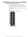
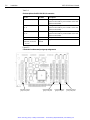
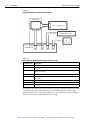
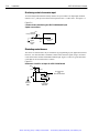
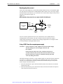

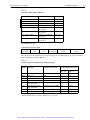

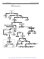
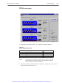
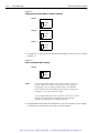
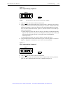
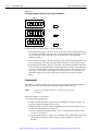
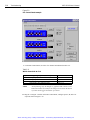
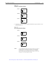
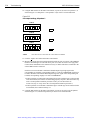


![[Unlocked] SC-2042](http://vs1.manualzilla.com/store/data/005660029_1-1367986a5e7a7fe673239a9957384234-150x150.png)