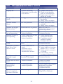
1
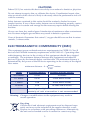
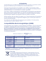
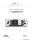
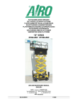
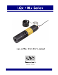
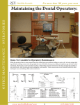
Digital Ultra™ User Manual
• Flushmount
• Flexmount
• Digital Newport
1
To be used in nitrous oxide-oxygen sedation systems for delivering to a patient
a mixture of nitrous oxide and oxygen gases with a maximum nitrous oxide
concentration of 70%.
INDICATIONS FOR USE
Contraindications for use of nitrous oxide/oxygen inhalation may include:
1. some chronic obstructive pulmonary diseases;
2. severe emotional disturbances or drug-related dependencies;
3. first trimester of pregnancy;
4. treatment with bleomycin sulfate;
5. methylenetetrahydrofolate reductase deficiency.
6. severe asthma
CONTRAINDICATIONS
Whenever possible, appropriate medical specialists should be consulted before
administering analgesic/anxiolytic agents to patients with significant underlying
medical conditions (e.g., severe obstructive pulmonary disease, congestive heart
failure, sickle cell disease, acute oritis media, recent tympanic membrane graft,
acute severe head injury.1 Operator must review patient history with regard to
these health issues.
1
American Academy of Pediatric Dentistry. Clinical Guidelines: Guidelines on Use of Nitrous Oxide for
Pediatric Dental Patients. Pediatr Dent 2009;31(6):148-151. Available at:
“http://www.aapd.org/media/policies.asp”. Accessed February 23, 2010.
To be used only by a professional trained in the use of nitrous oxide, using titration
method.
WARNINGS
Patient should always be closely monitored during nitrous oxide use. If patient
has an adverse reaction, reduce or stop the flow of nitrous oxide as needed. The
O2 flush button can be used to rapidly purge the lines of N2O. If patient does not
show signs of quick recovery, remove nasal hood and treat with pure oxygen from
either the O2 resuscitator fitting or an auxiliary oxygen tank using a demand valve,
oxygen assisted manual resuscitator, or equivalent. Call for emergency assistance if
rapid response is not achieved.
Do not use this device for the administration of general anesthesia or as part of, or
in conjunction with, a general anesthesia administration system.
For use with 100-240 V AC, 50/60 Hz only.
Use only hospital grade power cord connected to an equivalent receptacle marked
“Hospital Only” or “Hospital Grade.” For emergency power shut-off and isolation,
unplug power cord from wall outlet.
Unit is calibrated at the factory to ±5% per industry recommendations.
Verify that the correct gases are being delivered to the correct flowmeter inlets by
performing the oxygen failsafe test in section VII.
NIOSH recommends N2O levels in operator area be kept below 25 PPM.
Administer pure oxygen to patient for at least 5 minutes after nitrous oxide
procedure.
2
Federal (U.S.) law restricts this device to sale by or on order of a dentist or physician.
CAUTIONS
Do not attempt to repair, alter, or calibrate this device. Unauthorized repair, alteration or misuse of this device is likely to adversely affect the performance and will
void the warranty.
Safety features contained in this notice should be routinely checked to assure
proper function. If any of these safety features are not functioning properly, contact
your dealer or Accutron and arrange for the necessary repairs before reusing the
machine.
Always use clean, dry medical gases. Introduction of moisture or other contaminants
into Accutron analgesia gas machines may result in defective operation.
Users of electronic flowmeters that control % oxygen should be aware that Accutron
controls % nitrous oxide.
ELECTROMAGNETIC COMPATIBILITY (EMC)
This equipment passes radiated emissions requirements for CISPR 11 Class B
devices and EM field immunity requirements of IEC6100-4-3. Operating other
radio frequency devices in the vicinity of this equipment should be evaluated
accordingly. The minimum distance between this equipment and other RF
devices is given by the formula below and the table. The minimum distance is
determined by the power of the RF device operating in the vicinity of the digital
flow meter.
(Power)
minimum distance: d = ______ meters
0.388
Power
Distance (meters)
Distance (feet or inches)
0.01 Watts
0.258
10 inches
0.1 Watts
0.816
2 feet and 8 inches
1 Watts
2.58
8 feet and 6 inches
10 Watts
8.16
26 feet and 9 inches
over 10 Watts
Operating the digital flow meter within close
proximity of such a transmitter is not recommended.
Warning: Changes or modifications to the equipment may result in
unsafe operation.
Recycling
Old electrical and electronic equipment must be disposed separately and may not be included in the regular domestic waste.
Dispose in accordance with prevailing ordinances. Alternatively,
the unit can be handed over to Accutron for correct recycling.
3
Vous ne devez utiliser cette machine que dans des systèmes de sédation oxygèneoxyde nitreux qui livrent au patient un mélange de gaz d’oxyde nitreux et
d’oxygène ayant une concentration maximale d’oxyde nitreux de 70 %.
INDICATIONS D’UTILISATION
Les contre-indications sur l’inhalation d’oxyde azoteux/oxygène peuvent inclure:
1. certaines maladies respiratoires obstructives chroniques;
2. des troubles émotionnels graves ou des dépendances liées à la toxicomanie;
3. le premier trimestre d’une grossesse;
4. le traitement au sulfate bléomycinique;
5. une déficience en réductase d’acide tétrahydrofoliqueméthylène.
6. sever asthme
CONTRE-INDICATIONS
Dans la mesure du possible, consulter un spécialiste médical avant d’administrer
des agents analgésiques/anxiolytiques aux patients qui présentent des troubles
médicaux sous-jacents (par ex.: maladies respiratoires obstructives graves, défaillance cardiaque, drépanocytose, otite moyenne aiguë, greffon récent de la membrane du tympan, traumatisme crânien grave aigu.1 L'opérateur doit examiner
l'historique du patient à l'égard de ces problèmes de santé.
1
American Academy of Pediatric Dentistry. Lignes directrices cliniques: Lignes directrices sur l’utilisation de l’oxyde azoteux pour les patients dentaires pédiatriques. Pediatr Dent 2009;31(6): 148-151.
Disponible sur le site Web: “http://www.aapd.org/media/policies.asp”. Accès le 23 février 2010.
Pour être utilisé uniquement par un professionnel formé à l'utilisation de l'oxyde
nitreux en utilisant la méthode de titration.
AVERTISSEMENTS
Le patient doit toujours faire l’objet d’une surveillance étroite pendant l’utilisation
de l’acide azoteux. Si le patient présente des effets indésirables, réduire ou arrêter
le débit de l’acide azoteux, selon le besoin. Le bouton de purge O2 pour peut être
utilisé pour évacuer rapidement les lignes de N2O. Si le patient n’affiche aucun
signe de récupération rapide, enlever l’enceinte nasale de hood et le traiter avec
de l’oxygène pur, soit à partir du raccord du réanimateur O2 ou d’une bouteille
d’oxygène auxiliaire utilisant un détendeur, d’un réanimateur manuel assisté par
de l’oxygène ou l’équivalent. Demander de l’aide d’urgence si une réponse rapide
n’est pas obtenue.
Ne pas utiliser ce dispositif pour l’administration d’une anesthésie générale ou
comme partie ou encore en conjonction avec un système d’administration
d’anesthésie générale.
Pour une utilisation à 100-240 V AC, 50/60 Hz seulement.
Utilisez le cordon d’alimentation de qualité que l’hôpital connecté à une prise
équivalente portant la mention «Hôpital seulement» ou «Hospital Grade». Pour
pouvoir d’arrêt d’urgence et d’isolement, débranchez le cordon d’alimentation
de la prise murale.
Unité est calibré à l’usine de ± 5% selon les recommandations de l’industrie.
Vérifiez que le bon gaz sont livrés au bon débitmètre anses en effectuant l'oxygène
Failsafe Test dans la section VII.
Le NIOSH (USA) recommande N2O niveaux de zone opérateur être maintenu en
dessous de 25 ppm.
Administrer oxygène pur pour au moins 5 minutes après utilisation d'azote.
4
Conformément à la loi fédérale des États-Unis, cette machine ne peut être vendue
que par un dentiste ou par un médecin ou sur leur ordonnance.
ATTENTION
N’essayez jamais de réparer, de modifier ou de calibrer cet instrument. Toute
réparation, modification non autorisée ou mauvais usage de cet instrument nuira
considérablement à son rendement et annulera la garantie.
Vous devez vérifier couramment les caractéristiques de sécurité de cette brochure
pour assurer un bon fonctionnement. Si l’une des caractéristiques de sécurité ne
fonctionne pas bien, appelez votre revendeur ou Accutron et prenez les mesures
nécessaires pour réparer votre appareil avant de l’utiliser à nouveau.
Utilisez toujours des gaz médicaux propres, secs. Toute introduction d’humidité ou
d’autre contaminant dans un appareil d’analgésie à gaz Accutron provoquera un
mauvais fonctionnement.
Les utilisateurs de débitmètres électroniques qui contrôlent %O2 doivent être
conscients que Accutron contrôle %N2O.
Compatibilité électromagnétique (CEM)
Cet équipement passe exigences sur les émissions de CISPR 11 Classe B dispositifs
et exigences d'immunité de champ EM de IEC6100-4-3. l'autre opération les dispositifs de radiofréquence dans le voisinage de ces équipements doivent être évalués en conséquence. La distance minimale entre cet équipement et d'autres RF
appareils est donnée par la formule ci-dessous et le tableau. La distance minimum
est déterminée par la puissance du dispositif RF fonctionnant dans le voisinage de
la numérique débitmètre.
distance minimale: d = _________ mètres
0.388
(Puissance)
Puissance
Distance (mètres)
Distance (pieds ou en pouces)
0,01 Watts
0.258
10 pouces
0,1 Watts
0.816
2 pieds et 8 pouces
1 Watts
2.58
8 pieds et 6 pouces
10 Watts
8.16
26 pieds et 9 pouces
plus de 10
Watts
de fonctionnement du débitmètre numérique dans
près la proximité d'un tel émetteur est déconseillée.
Attention: Les modifications apportées à l'équipement peuvent entraîner
des fonctionnement dangereux.
Recyclage
Les anciens équipements électriques et électroniques doivent
être éliminés séparément et ne peuvent pas être inclus dans les
déchets domestiques réguliers. Éliminer conformément aux
règlements en vigueur. Autrement, l'appareil peut être remis à
Accutron pour le recyclage correct.
5
Table of Contents
I.
II.
III.
Page
Warnings and Cautions . . . . . . . . . . . . . . . . . . . . . . . . . . . . . . . . . . 2
Technical Specifications . . . . . . . . . . . . . . . . . . . . . . . . . . . . . . . . . . 7
Control/Display Features . . . . . . . . . . . . . . . . . . . . . . . . . . . . . . . . 8
Digital Flowmeter Models
Flushmount. . . . . . . . . . . . . . . . . . . . . . . . . . . . . . . . . . . . . . . . . 10
Flexmount . . . . . . . . . . . . . . . . . . . . . . . . . . . . . . . . . . . . . . . . . . 12
IV.
Digital Newport . . . . . . . . . . . . . . . . . . . . . . . . . . . . . . . . . . . . . 14
Safety Features . . . . . . . . . . . . . . . . . . . . . . . . . . . . . . . . . . . . . . . . . 18
V.
General Instructions . . . . . . . . . . . . . . . . . . . . . . . . . . . . . . . . . . . . . 18
VII.
Periodic Equipment Checks . . . . . . . . . . . . . . . . . . . . . . . . . . . . . . 23
VI.
VIII.
IX.
Directions for Use . . . . . . . . . . . . . . . . . . . . . . . . . . . . . . . . . . . . . . . 19
Troubleshooting Guide . . . . . . . . . . . . . . . . . . . . . . . . . . . . . . . . . . 25
Warranty. . . . . . . . . . . . . . . . . . . . . . . . . . . . . . . . . . . . . . . . . . . . . . . 26
X.
Warranty & Returned Goods Policy . . . . . . . . . . . . . . . . . . . . . . . 27
XII.
Assistance. . . . . . . . . . . . . . . . . . . . . . . . . . . . . . . . . . . . . . . . . . . . . . 27
XI.
XIII.
Repair Service Policy . . . . . . . . . . . . . . . . . . . . . . . . . . . . . . . . . . . . 27
Ownership Information . . . . . . . . . . . . . . . . . . . . . . . . . . . . . . . . . . 27
© September 2014 Accutron, Inc.
Part No. 26256 - Rev. 04
6
I. TECHNICAL SPECIFICATIONS
Flushmount Main Unit
Flushmount Controller
Flexmount
Digital Newport
Physical
8x4x7.5” (20,3x10,2x19 cm) Weight:
9x4x1.5” (22,9x10,2x3,8 cm) Weight:
8x4x7.5” (20,3x10,2x19 cm) Weight:
19x32x22” (48x80x56 cm) Weight:
5.2 lbs (2,4 kg)
1.0 lbs (0,8 kg)
8.2 lbs (3,7 kg)
75 lbs (34 kg)
100-240 V AC
50/60 Hz.
0.5 A
Socket is IEC/EN 60320-1 C14 and accepts an IEC/EN 60320-1 C13 connector
Power cords available for most countries
Electrical
Lithium coin battery, 3v CR2032
Internal Battery
T500mAL, 250v (quantity 2) Accutron part number 26456-FRU
Fuses
Oxygen: 50-55 PSI at 100 LPM min.
Nitrous Oxide: 50-55 PSI at 10 LPM min.
Gas Supply
Oxygen Inlet: Male DISS CGA 1240
Nitrous Oxide Inlet: Male DISS CGA 1040
Mixed Gas Outlet: Male DISS CGA 1160 or 1/4” Hose Barb
Oxygen Resuscitator Connection: 1/4" I.D. Quick Disconnect
Adapter hoses available for AGA, DIN, NIST, BOC, AFNOR, SIS, UNIFO
Gas Fittings
Oxygen Flush: Minimum 20 LPM
Oxygen Flow: 1.0 LPM-9.9 LPM (Accuracy +/- 0.5 LPM)
Oxygen %: 30%-100%
Oxygen Resuscitator Flow: Minimum 100 LPM, 100% O2
Nitrous Oxide Flow: 0-6.9 LPM (accuracy +/- 0.5 LPM)
Nitrous Oxide %: 0-70%
Mixed Gas Flow: 1.0-9.9 LPM
Gas Delivery
Transportation/Storage: Temperature: -40°C to +70°C (-40°F to 158°F)
Humidity: 10-100%
Environmental
Operating Conditions:
Temperature: 15°C to 32°C (68°F to 90°F)
Humidity: 30-75%
Atmospheric Pressure: 72-101 kPa (543-760 mmHg)
Printer
Remote Control
Remote Flow System (RFS)
Accu-Vac
Accessories
Scavenging Circuit II
Scavenging Circuit II (RFS)
Scavenging Circuit II, ClearView
Scavenging Circuit II, ClearView (RFS)
Applied Part (rated BF)
7
PN32007
PN32009
PN43003
PN43004
II. CONTROL/DISPLAY FEATURES
Front Control/Display Panel
% N2O
Display
N2O Bar
Display
O2 Bar
Display
Information LEDs
Total Flow in this area
Display
Increase
Total
Flow
Increase
% N2O
Decrease
Total
Flow
Decrease
% N2O
Cancel/ Test
Vacuum LED
Print
N2O
Display
O2
Display
O2
Flush
Remote Control
Increase
Total Flow
Increase
% N2O
Decrease
Total Flow
Decrease
% N2O
Power
(On/ Off)
O2 Flush
8
Power
(On/ Off)
Front Control/Display Panel & Remote Control
Control/Display Panel – Easy-to-use control panel allows setting Total Flow and
N2O concentration with the touch of a finger. Bright, color-coded displays make it
simple to monitor status, even from a distance. Optional hand-held Remote allows
functional control at patient chairside.
Total Flow Control – Allows setting of Total Flow in either (.1) LPM or (.5) LPM
increments. Once set, the Total Flow will remain constant even if % N2O is
changed.
Total Flow Display – Shows Total Flow in numeric LPM format with yellow LEDs.
% N2 O Control – Allows setting of N2O concentration in either 1% or 5% increments up to a maximum of 70%. Once set, % N2O will remain constant even if Total
Flow is adjusted.
% N2 O Display – Shows % N2O in numeric format with blue LEDs.
Power – Turns unit on and off with the push of a button.
Flush Control – Ceases N2O Flow and provides a minimum of 20 LPM of pure O2
as long as button is pressed.
O2 Flow – Two green LED displays show O 2 Flow in both LPM numbers and
graphic bars simulating standard flow tube.
N2 O Flow – Two blue LED displays show N2O Flow in both LPM numbers and
graphic bars simulating standard flow tube.
Print – When optional printer is installed, provides printout of current conditions.
Cancel/Test – During an alarm mode, turns off audio alarm for one minute.
During normal mode, performs self-check of all displays.
Information LEDs – Informs administrator of failures with O2 supply, N2O
supply, O2 flush, or mixed gas line to patient. Also indicates if remote vacuum is
connected.
9
III. FLOWMETER MODELS
FLUSHMOUNT MODEL
Two piece design for easy installation into a cabinet or a wall. Thin control module
located away from main module, power, and gas lines, requires remote outlet.
Flushmount Remote Outlets Options
a) Standard
Sample Installation
(Contains m ixed
gas outlet and
O2 resuscitator
connection)
b) Remote Flow
System (RFS)
(Contains m ixed
gas outlet, O2
resuscitator, and
vacuum controller
w ith gauge d isplay)
O2
15 10
20
in Hg 5
0
30
25
VACUUM
Green Light
MIN
MAX
VAC
MAX
O
2
c) Accu-Vac
(Contains m ixed gas outlet,
O2 resuscitator, and vacu-
Cabinet
Mounting
10
Remote Control
Remote Vacuum 12 V DC Out
RS232 Printer
N2O In
O2 In
100-240 V AC Inlet
IEC/ EN 60320-1 C14
with two fuses.
(Accep ts IEC/ EN
60320-1 C13 co nnecto r)
Mixed Gas Out (O2/ N2O)
– Connects to remote bag
tee outlet
O2 Out – Connects to O2
Resuscitator fitting on
remote outlet
Flushmount Main Module Utility Connections
O2 Inlet – Labeled O2 IN – Equipped with male CGA 1240 DISS fitting to prevent
gas mix-up.
N2 O Inlet – Labeled N2O IN – Equipped with male CGA 1040 DISS fitting to
prevent gas mix-up.
O2 Out – Labeled O2 OUT – Equipped with male CGA 1240 DISS fitting, provides
oxygen for resuscitator.
Mixed Gas Port – Equipped with male CGA 1160 DISS fitting (Medical Air)
Power Cord Inlet – Clearly labeled 100-240 V AC, 50/60 Hz and protected by two
fuses for added safety. Fuses are 240 V, 0.5A, slow-blow. To disconnect power,
unplug cord. Do not position where this disconnection would be difficult.
RS232 Printer Connector – Clearly labeled and designed for use with optional
Accutron-approved printer.
Remote Control Connector – Remote Control connection. Using the Remote
Control, general adjustments can be made from a distance of up to 10 feet
away from device.
Remote Vacuum Valve Connector – Clearly labeled and designed to actuate a
vacuum valve in the Accu-Vac Automatic Vacuum Scavenging Port (PN 56955).
O2 Out Connector – Direct connection to oxygen for use with resuscitator.
Provides minimum of 100 LPM of oxygen.
11
FLEXMOUNT MODEL
Can be mounted on a
number of different
devices.
O2 Resuscitator Fitting
Mixed Gas Port for Bag Tee
Flexmount Mounting Options
4-Cylinder Portable System
9" Wall Arm
Mobile Stand
16" Bi-fold Wall Arm
12
Telescoping Wall Arm
(Extends 12"-17")
Remote Control
Remote Vacuum 12 V DC output
RS232 Printer
N2O Inlet
O2 Inlet
100-240 V AC Inlet
IEC/ EN 60320-1 C14
With 2 Fuses
(Accep ts IEC/ EN
60320-1 C13 co nnecto r)
Mixed Gas Out (O2/ N2O) –
Connects to bag tee port on
front of unit
O2 OUT – Connects to
O2 Resuscitator fitting
on front of unit
Flexmount Utility Connections
O2 Inlet – Labeled O2 IN – Equipped with male CGA 1240 DISS fitting to prevent
gas mix-up.
N2 O Inlet – Labeled N2O IN – Equipped with male CGA 1040 DISS fitting to
prevent gas mix-up.
O2 Out – Labeled O2 OUT – Connects to oxygen resuscitator fitting on front.
Mixed Gas Out – Connects to bag tee port on front.
Power Cord Inlet – Clearly labeled 100-240 V AC, 50/60 Hz and protected by two
fuses for added safety. Fuse ratings are 240 V, 0.5 A, slow-blow. To disconnect
power, unplug cord. Do not position meter where this disconnection would be
difficult.
RS232 Printer Connector – Clearly labeled and designed for use with optional
Accutron-approved printer.
Remote Control Connector – Remote Control connection. Using the Remote
Control, general adjustments can be made from a distance of up to 10 feet
away from device.
O2 Out Connector – Direct connection to oxygen resuscitator fitting on front.
Provides minimum of 100 LPM of oxygen.
13
DIGITAL NEWPORT
Regulators and
E Yokes
Line
Pressure
Gauges
Gas
Cylinders
Remote
Control Port
(Optional)
O2
Resuscitator
Fitting
Tank
Restraint
Removable
Bag Tee
If printer option is
installed, printer cable
will extend from cover
at this point.
Handle
Warning: Do not
hold handle when
opening cabinet.
10’ Hospital Grade
Power Cord
Power Socket
Note: Power Cord must
be either unplugged from
socket or unwound from
storage cleats when
opening Newport.
To disconnect power,
unplug cord. Do not position where this would be
difficult.
14
Digital Newport Setup and Connections
View – When looking at the front of the Newport cabinet, Nitrous Oxide is on the
left as shown by the blue Nitrous Oxide gauge. Oxygen is on the right as shown by
the oxygen gauge.
Opening Newport Cabinet – Open the Newport cabinet by placing one hand on
the front cover and the other in the handle on the side. Pull handle back all the
way. Make sure the power cord is unplugged from the socket in the skirt first.
Install Gas Cylinders –
1. Undo Velcro straps
2. Angle tank into position
3. Strap tanks loosely
4. Remove regulators from accessories box
5. Attach regulators to tanks by loosening yoke handle, verifying seal is in
place, aligning seal with gas opening, aligning pins with holes in yoke,
tightening yoke onto cylinder
NOTE: Regulators are pinned to match gas cylinders. Connect gas hoses to
regulator outputs.
NOTE: Hoses and regulators use DISS fittings to prevent mix up. Rotate cylinders
so that regulators fit inside.
Open Gas Cylinders – Pick one tank of each gas to be “in use“ tank and attach “in
use” label to cylinder. Open these cylinders using the cylinder wrench provided in
accessory box. Close Newport cabinet.
Connect Power –
1. Plug cord back into skirt outlet
2. Plug other end of cord into receptacle
NOTE: System will operate from 100-240 V, 50-60 Hz. Internal power supply will
switch automatically.
Scavenging Circuit –
- Install bag tee from accessories box into front of Newport.
- Attach scavenging circuit to bag tee.
- Connect vacuum hose to system vacuum.
- Install nasal hood into scavenging circuit and start vacuum flow per
scavenging instructions.
Start up – See Section VII , Directions For Use
15
Digital Newport: Managing Gas Supply
Note: Power Cord must be either unplugged from socket or unwound from
storage cleats when opening Newport.
1.
2.
3.
4.
5.
Identify the two in-use tanks (N2O and O2) by attaching “in-use” identification
tags to them.
When one of the in-use tanks is empty, close the tank by turning the valve
clockwise. Leave the empty tank in place.
Move the “in-use” tag to the appropriate reserve tank, which now becomes
the in-use tank. Replace the empty tank with a new tank, which then becomes
the reserve tank.
Open the valve of the new in-use tank by turning counterclockwise.
Note: Do not open the reserve tank until the in-use tank is empty. When
changing gas tanks, make certain both same gas cylinders that are
involved in the exchange are closed. Always remember to switch
the “in- use” tags over to the new tanks.
Contact gas supplier to request new gas cylinders as needed.
Digital Newport: Changing Gas Cylinders
Always use clean, dry medical grade gases. Introduction of moisture or other
contaminants into Accutron Analgesia gas machines may result in defective
operation.
The Digital Newport Flowmeter System is designed to operate with a
50-55 psi line pressure on each gas (O2 and N2O). The line pressure can be
determined by reading the O2 and the N2O line pressure gauges that are located
on the front panel of the Newport.
The Newport has features incorporated to make cylinder change-out easy. To
assure proper operation of the system, 4 cylinders must be properly installed at
all times. Please review the following cylinder replacement procedures before
attempting to change cylinders.
Note: Power Cord must be either unplugged from socket or unwound from
storage cleats when opening Newport.
1.
2.
3.
4.
5.
6.
Open the tank enclosure by sliding the cover to the rear.
Close the valve on the empty tank (clockwise).
Release the Velcro restraint on the empty tank.
Tilt the empty tank out slightly.
Loosen the round handle on the regulator yoke.
Remove the regulator from the empty tank (make certain that the regulator is
not dropped or damaged while it is off the tank).
7. Lay the empty cylinder down on the floor (cylinders should only stand
upright when properly restrained as they can easily fall over).
8. Pick up the full replacement tank and place the bottom of the tank onto the
floor of the Newport, leaving it slightly tilted outward for easy replacement of
the regulator.
9. Check to assure that the sealing gasket has remained on the regulator’s E yoke.
10. Reattach the regulator to the new full tank by sliding the yoke (attached to
the regulator) over the top of the tank post aligning the index pins with the
corresponding holes in the tank post.
11. Tighten the round handle on the regulator yoke.
12. Push the tank into an upright position. Attach and tighten the Velcro
tank restraint.
16
Digital Newport:
Control Module and Main Module Locations
Control
Module is
behind
shield at
front of
unit.
Serial #
Label
Main flowmeter module
is behind shield at rear
of unit. Fuses are located in
fuse tray at power
cord socket on back of
flowmeter.
17
IV. SAFETY FEATURES
O2 Fail Safe System – Offers assurance that N2O ceases if the O2 supply is
interrupted or reduced. Alarm will sound, FAILURE OXYGEN LEDs will light,
and N2O flow will cease.
N2 O Supply Warning – Triggers an alarm if the N2O supply cannot keep up with
user’s needs. Alarm will sound and FAILURE NITROUS LEDS will light. Flow
switchs to 100% oxygen.
Mixed Gas Flow to Patient – Monitors pressure in mixed gas line and triggers an
alarm if flow to patient is obstructed. Alarm will sound and FAILURE NITROUS
OXYGEN LEDS will light.
Emergency Air Valve – Automatically provides patient with ambient air if gas flow
is interrupted. Located on remote bag tee.
Directional Check Valve – Prevents re-breathing of exhaled gases and protects
against CO2 buildup. Located on remote bag tee.
O2 Resuscitator Connection – Direct connection to O2 for use with resuscitator. Port
is always open and provides 100 LPM minimum of pure oxygen.
V. GENERAL INSTRUCTIONS
1. Warranty
Unpack Digital Ultra and inspect to make certain that the unit has not been
damaged during shipment.
The unit’s serial number is located on the back of Digital Ultra (see page 17 for
Digital Newport's serial number location). Record the serial number in the area
provided at the back of this booklet. Once Digital Ultra Flushmount is mounted
into a cabinet, the serial number will no longer be visible. Always reference the
serial number when corresponding with Accutron.
Complete the warranty card supplied with Digital Ultra and mail to Accutron.
Completion of this step ensures proper device warranty coverage. Accutron Digital
Ultra analgesia machines carry a two-year limited warranty (see Warranty on page
26 for details).
2. Gas Supply Connection
Always use clean, dry medical gases. Introduction of moisture or other contaminants into Accutron analgesia gas machines may result in defective operation.
After device installation, connect the oxygen and nitrous oxide supply lines to the
Diameter Specific Instant fittings or DISS fittings located on the back of the device.
See pages 14-16 for information specific to the Digital Newport. It is important that
the regulators for both gases be set to give pressures in the range of 50-55 PSI.
Verify that the correct gases are being delivered to the correct ports on device
before initial use. This can be done by shutting off the O2 cylinders and turning the
unit on. The unit should immediately go into an oxygen failure fault mode. If unit
indicates O2 gas is flowing, lines are crossed. Correct before using.
18
3. Power Connection
Device is designed to run on 100-240 V AC and 50/60 Hz. There is no need to flip
an external switch; the unit automatically adjusts for any power. A medical-grade
power cord is supplied with the unit and must be used to ensure proper grounding.
It is important that the power cord be plugged into an outlet marked “Hospital
Only” or “Hospital Grade.” The power cord is plugged into the AC entry, which
contains two fuses and is located on the back of the device. International power
cords are offered for most countries. Use only 240 V, 0.5A, slow-blow fuses. Fuses
can be ordered from Accutron as part number 26456-FRU.
4. Auxiliary Connections
Plug remote control into remote port on back of Digital Ultra or on front cover of
Newport if ordered as option.
Plug Accu-Vac signal line into vacuum connector on back of Digital Ultra
(Flushmount only). Vacuum LED should light when Digital Ultra is powered
indicating vacuum is flowing.
Plug printer cable from Able printer, if used, into RS232 printer port. Do not use this
port for any other devices. If printer is ordered on Newport as option, printer cable
will extend from front cover. Note: Use only Able printer supplied by Accutron.
VI. Directions For Use
Read instructions completely before operating Digital Ultra device.
Note: The steps listed below provide a basic functional description of the Digital Ultra
usage. A training course that emphasizes a practical, hands-on approach combined
with instructions on safe techniques for administration of nitrous oxide-oxygen conscious sedation is recommended before use of this flowmeter. Do not use this device
for the administration of general anesthesia or as part of, or in conjunction with, a
general anesthesia administration system. Unit must be connected to O2 and N2O
gases at 50-55 PSI. Unit must be plugged into 100-240 V AC, 50/60 Hz power outlet.
Use titration method for administering nitrous oxide.
Pow er button w ill shut off Digital Ultra norm al functions (reference d iagram on
page 8). For Em ergency shutoff, unplug pow er cord .
NOTE: Detailed information on users, patients, and conditions can be found at the
end of section VI.
General Operating Instructions
Setup:
Verify the presence of separate means of oxygen resuscitation and that appropriate staff
are trained in its operation.
WARNING: In cases of adverse reactions, discontinue nitrous oxide procedure, remove
scavenging circuit, utilize auxiliary resuscitation measures and equipment, and
contact Emergency Responders (911).
Verify that oxygen and nitrous gases have not been mixed up by performing the
Oxygen Failsafe Test on page 23. Note: the only significant source of injury from
nitrous oxide procedures is gas mix-up.
Open inlet gas supplies for oxygen and nitrous oxide by:
a. Turning on manifolds in central systems or
b. Opening gas cylinders in Newports and 4 cylinder mobile stands
Verify scavenging vacuum is turned on and properly set per scavenging circuit
Instruction for Use
Verify power to flowmeter
19
Operation:
1) Push POWER button on front membrane or on Remote Controller.
(Initial flow is set to 5.0 lpm at factory but can be adjusted per instructions on page 21)
2) Install scavenging circuit per scavenging circuit Instructions for Use.
3) Adjust proper breathing flow by using the TOTAL FLOW and TOTAL FLOW
buttons. Reservoir bag should inflate and deflate in response to patient breathing
but never go completely full or completely empty. (Increments are set at factory to
0.5 lpm but can be reset to 0.1 lpm increments per instructions on page 20).
4) Gradually add nitrous oxide by using the % N2O . It is recommended that % start
at 10% and be increased by 10% intervals until desired reaction is achieved. Allow
time between each change for patient to adjust since rapid increasing of N2O %
can cause nausea. (Increments are set at factory to 5% but can be adjusted to 1%
per instructions below)
Note: Total flow does not change if % N2O changes and % N2O does not
change if Total Flow changes.
Caution! Accutron controls % N2O. Refer to page 22 for possible Use Error for
those who are used to meters that control % O2.
5) Max % N2O is set at the factory to 70%. This limit can be changed to 50% by
following instructions on page 21.
6) Adjust Total Flow and % N2O as needed to maintain proper anxiety relief and
proper flow levels.
7) Turn % N2O to 0 at the end of the procedure by using the % N2O. Continue with
pure oxygen for 5 minutes.
8) Stop gas flow by pushing POWER at the end of the procedure. Remove scavenging
circuit and close vacuum.
Additional Functions:
Print - If a Printer is installed, a snap shot of current O2 flow, N2O flow, Total
Flow, % N2O, Time and Date can be printed by pushing PRINT.
Mute - During an alarm condition, sound is muted by pushing CANCEL/TEST
Led Test - During normal operation, CANCEL/TEST will cycle though
all Leds to verify all are operational
Flush - A minimum 20 lpm of pure oxygen will flow when FLUSH is pushed
Setting Step Size of Total Flow and % N2O
1.
2.
3.
4.
To set the % N2O step size to 5%: Plug in Digital Ultra and leave off. Press
and hold % N2O Up (+) button until beeps (approx. 5 seconds).
To set the % N2O step size to 1%: Plug in Digital Ultra and leave off. Press
and hold % N2O Down (-) button until beeps (approx. 5 seconds).
To set Total Flow step size to 0.5 LPM increments: Plug in and turn off Digital
Ultra. Press and hold Total Flow Up (+) button until beeps (approx. 5 seconds).
To set Total Flow step size to 0.1 LPM increments: Plug in and turn off Digital
Ultra. Press and hold Total Flow Down (-) button until beeps (approx. 5 seconds).
Setting Date and Time
1.
2.
3.
4.
5.
6.
Plug in Digital Ultra and leave off.
Press and hold Print button down until beeps (approx. 5 seconds). This will
start year setting.
Display will show 20 in % N2O box and flashing display in Total Flow box.
Adjust to current year using Total Flow Up/Down buttons. Push % N2O Up
(+) button to store value and proceed to next step.
% N2O box now displays months. Set the month with Total Flow Up/Down
buttons. Push % N2O Up (+) button to store value and proceed to next step.
Total Flow box now displays days. Set the day with Total Flow Up/Down
buttons. Push % N2O Up (+) button to store value and proceed to next step.
20
7.
8.
N2O box now displays the hours. Set the hour with Total Flow Up/Down
buttons. Push % N2O Up (+) button to store value and proceed to next step.
N2O box now displays minutes. Set the minute with Total Flow Up/Down
buttons. Push the cancel button to save value and exit program.
Changing Starting Total Flow Rate
With power connected and flowmeter off, press and hold CANCEL/TEST and
Total Flow + (up) Arrow together until beep (5-7 seconds). Current Total Flow will
be shown. Adjust to desired flow rate using Total Flow + Up and Total Flow Down buttons. Acceptable values are 1.0 to 9.9 LPM. Press Flush button to accept
new value. Starting Total Flow will now start at the new value.
Changing Max N2O Percentage (50% 70%)
With power connected and flowmeter off, press and hold CANCEL/TEST and N2O
% Up + buttons together until beep (5-7 seconds). This will toggle between 50% and 70%.
Changing Operating Mode (Normal/Demo)
With power connected and flowmeter off, press and hold CANCEL/TEST and O2
FLUSH buttons together until beep (5-7 seconds). This toggles between Normal
(gas flow) mode and DEMO (no gas flow). When in Demo mode, unit will start up
flashing SALES for 5 seconds. In this mode, controls and displays will act normal
but no gas will be needed or allowed to flow.
Set to Constant 50/50 Mode
This is done at the factory via an internal switch. In 50/50 mode, unit will supply a
constant 50% Nitrous Oxide/50% Oxygen mix. Total Flow can be adjusted but will
remain 50/50. As a safety feature, the unit can be toggled back and forth between
50/50 and 100% oxygen by using the Nitrous % Up and Down Arrows. 50/50
mode is often used in ERs to minimize shock and in Obstetrics for labor pains.
Application Specifications
Intended Use
The Accutron Digital Flowmeter is used to reduce anxiety in dental patients so that
traditional treatments can be performed more efficiently and with less stress on the
patient.
Intended Medical Indication
Nitrous oxide in Accutron approved applications is used for anxiety relief and is
not a treatment for any particular medical indication per se. It is used to calm
patients so that other treatments may be performed. It is proscribed for conscious
sedation only and not for use with other anesthesia agents.
Intended patient population
Nitrous oxide is routinely given to healthy individuals over 2 years of age without
distinction of age, sex, or weight. See pages 2 and 3 for contra-indications.
NOTE: Patient reaction to nitrous oxide can vary widely between individuals and
even in same individuals over time. Some individuals can not tolerate any N2O.
Intended part of the body
Nitrous oxide is a gas and is delivered to the nose via a nasal hood connected to
gas supply tubing. The patient inhales the gas which is then absorbed in the lungs.
21
Intended user profile
Medical professionals such as doctors, dentists, dental assistants, dental hygienists,
and nurses who have been formally trained in the use of nitrous oxide and who
have studied the operating instructions in the User Manual.
Intended conditions of use
The Accutron Digital flowmeter is intended to be used in medical facilities such as
dental offices and hospitals with standard controlled room environments. See section I for further environmental specifications. Units may be mounted in cabinets,
on extension arms, on sliding brackets, or on mobile carts. Units are not meant to
be hand mobile by personnel and are not meant to be used in emergency vehicles.
Frequency of use can vary from rare (once a month) to (frequent) 10-15 times per
day. The user interface is designed for asepsis cleaning.
Description and operating principle
The Accutron Digital PC Flowmeter is a microprocessor-controlled device that
precisely meters Oxygen and Nitrous Oxide gases for analgesic purposes in Dental
Offices and Hospitals. The flowmeter is powered by 100-240 VAC, 50/60Hz via a
power cord that is plugged into a filtered inlet. This voltage is then automatically
converted to 24 VDC by a switching medical grade power supply. All components
within the flowmeter as well as the user interface are operated on 24 VDC or less.
Precise flow of both oxygen and nitrous oxide are achieved through a feedback
circuit containing a proportioning solenoid, a medical grade mass flow sensor, and
the main microprocessor. The mass flow sensors measure flow electronically giving real time updates to the circuit board which directs the solenoids to maintain
desired flow rates. The processor monitors these flows and gives alarms as needed
if the flow of either gas can not match the desired rates. The software also prevents nitrous oxide from flowing without oxygen and maintains oxygen levels at
30% or more at all times.
Clinical operation is very simple as there are only two items to control, TOTAL
FLOW and %N2O. Press POWER to start flow which comes on at 5.0 LPM Total
Flow and 0 %N2O. Adjust Total Flow with the + and – keys until it matches the
patients breathing rate. Increase % N2O by using the + and – keys until proper
relaxation is achieved. Decrease % N2O to 0 at end of procedure and continue with
pure oxygen for 5 minutes. Turn Power off. Total Flow and %N2O can be adjusted
during procedure as needed. Pure oxygen flush is available at any time. Print
option is also available.
Possible Use Errors
• Administering too much N2O or increasing the %N2O too quickly
• Mistaking the %N2O with %O2 used by other electronic flowmeters
• Not taking sufficient patient history before starting procedure
• Not reading the instructions for use or undergoing nitrous oxide training prior to
starting procedure
Abnormal Use
Disregarding the instructions and warnings is considered abnormal use.
22
Training
The intended use is the basis for training which is considered mandatory for all
operators prior to use. General Theory on nitrous oxide use and procedures are
described in such books as Nitrous Oxide and Oxygen Sedation by Clark and
Brunick and Lachgas by Dr Mathers. It is recommended that users undergo classroom training as well as hands on lab instruction. US training can be found in
numerous ADA sponsored continuing education courses. European training can be
obtained through the Institute for Dental Sedation, Cologne, Germany
(http://www.sedierung.com) or through BIEWER medical (http://www.biewermedical.com/en/sedation-training), Koblenz, Germany. Consideration of currently
valid local and national guidelines for training is required.
VII. PERIODIC EQUIPMENT CHECKS
CAUTIONS
Do not attempt to repair, alter, or calibrate this device. Unauthorized repair, alteration or misuse of this device may adversely affect the performance and will void
the warranty.
IMPORTANT
Safety features contained in this notice should be routinely checked to assure proper function. If any of these safety features are not functioning properly, contact
your dealer or Accutron and arrange for the necessary repairs before reusing the
machine.
Fail Safe Test
Check Before Each Use
Display Test
Check Before Each Use
Cleaning
Perform After Each Use
Turn on Digital Ultra and set Total Flow to 5.0 LPM and 50% N2O. Turn off O2 supply tanks. Audio alarm should sound when oxygen runs out, N2O should shut off,
and Failure and Oxygen Alarm LEDs should flash. Turn O2 back on, normal flow
should resume and alarms should cease.
Turn Digital Ultra on and press CANCEL/TEST button. All displays should light
sequentially with an audio beep, including alarms.
Wipe with damp cloth. Do not allow liquids to touch rear auxiliary connections or
enter case.
Oxygen Flush Valve Test
Check Monthly
•
Turn Digital Ultra on at 5.0 LPM and leave nitrous oxide at 0%.
•
Disconnect the corrugated tube from the bag tee outspout. Reservoir bag
should remain connected to the bag tee downspout.
•
Push the Flush button on Front Panel or Remote Control while blocking
the flow from the outspout.
Reservoir bag should fill within 5-10 seconds. Remove any blockage when
test is complete.
23
Outspout Check Valve Test
Check Monthly
•
Digital Ultra should be off.
•
Reservoir bag should be connected to the bag tee downspout.
•
Mixed Gas tube should be connected to the outspout but not connected
to the white patient delivery tubing.
•
Breathe into the open end of the corrugated tube.
The reservoir bag should not fill.
Override Air Valve Test
Check Monthly
•
Digital Ultra should be off.
•
Reservoir bag should be connected to the bag tee downspout.
•
Mixed gas tube should be connected to the outspout but not connected
to the white patient delivery tubing. Reservoir bag should be deflated.
•
Draw air through the open end of the corrugated tube.
The Override Valve should open and allow air to enter the corrugated
tube. Place your finger over the Override Valve and remove it to verify
that air is entering the bag tee through the Override Valve. If the Override
is not functioning, do not use Digital Ultra until it is repaired or replaced.
Factory Check
Recommended every 2 years or more frequently as required by prevailing
local and national codes.
Send equipment to authorized Service Center for operational check, battery
replacement, and recalibration. Note: battery used for time and date info
only, loss of battery does not affect safety or operation.
Routine Maintenance
There is no required routine maintenance as long as recommended factory
check is at least in the recommended period or more frequently as required by
prevailing local and national codes. Unit should only be repaired by trained individuals with specialized equipment. Unauthorized opening of equipment will put
individual at risk of electrical shock and will void Warranty.
Disinfecting
The following products are approved for disinfecting the front touch pad area. Do
not allow spray or liquid to enter any connectors on back of unit.
Lysol® Brand II I.C. Disinfectant Spray
EcoTru® Spray
ProSpray Surface Disinfectant
COE Foam II
CaviCide®
Microstat2™
NOTE: DO NOT USE BLEACH
24
VIII. TROUBLESHOOTING GUIDE
Display off
PROBLEM
1. Power cord loose
2. No power to wall outlet
3. Fuse blown
Oxygen Failure
alarm
Low O2 pressure
POSSIBLE CAUSE
1. Connect cord firmly
2. Check circuit breaker
and/or call electrician
3. Replace fuse in holder
under AC socket.
REMEDY
1. Verify O2 input to
flowmeter
2. Verify valves are open
Nitrous Failure
alarm
Low N2O pressure
Front panel buttons
are not operating
1. Defective panel
2. Internal problem
Contact Accutron
Customer Service
Displays don’t
work
Broken display/circuit
board
Contact Accutron
Customer Service
Flush does not have
enough oxygen
flow
Filter clogged
O2 solenoid damaged
Flow doesn’t
appear to be
accurate
1. Calibration error
2. Internal problem
Nitrous & Oxygen
Failure alarm
Remote Control is
not operating
Automatic Vacuum
port (Accu-Vac)
doesn’t work
Obstructed flow to patient
1. Loose connection to unit
2. Defective Remote
3. Internal problem
1. Loose connection in
back
2. Defective valve
3. Internal problem
4. Insufficient vacuum
1. Verify pressure in N2O
cylinder
2. Verify valves are open
Remove kinks or
obstructions from mixed
gas line to patient
1. Check remote plug
connection on back
2. If problem persists
contact Accutron
Customer Service
1. Check plug connection
2. Verify output of vacuum
outlet is 12 +/- 3 V DC
3. Verify system vacuum is
> 8 in Hg
4. If not solved, contact
Accutron Customer Service
Contact Accutron
Customer Service
Flush does not work 1. Internal Problem
at all
Contact Accutron
Customer Service
Unit freezes,
doesn’t respond,
gas won’t shut-off
Unplug power cord
Plug back in (Reboot)
1. Processor problem
25
Check output with Oxygen
Analyzer if available
Contact Accutron
Customer Service
IX. WARRANTY
ACCUTRON 2-YEAR FLOWMETER LIMITED WARRANTY
IF AN ACCUTRON FLOWMETER NEEDS TO HAVE REPAIR WORK OR
REPLACEMENT PARTS DURING THE 2-YEAR WARRANTY PERIOD DUE TO
MANUFACTURING DEFECTS, ACCUTRON WILL PROVIDE THE PARTS AND
LABOR AT NO CHARGE. THE FLOWMETER OWNER IS RESPONSIBLE ONLY
FOR A $35.OO SHIPPING AND HANDLING FEE, WHICH WILL BE ASSESSED
EACH TIME A FLOWMETER IS RETURNED TO ACCUTRON FOR WARRANTY
WORK.
WARRANTY TERMS
Limited Warranty and Disclaimer: Accutron (“Seller”) warrants that its product
will be free from manufacturing defects subject to the terms, conditions, and
limitation set forth hereinafter, for a period of 2 years for flowmeters and 1 year
for other equipment products. Seller’s obligations under this limited warranty
are contingent on Buyer’s full payment of the product purchase price. Except as
specifically set forth above, Seller and its affiliates make no warranties, expressed
or implied, and specifically disclaim any warranties of merchantability or fitness
for a particular purpose.
The liability of Seller and its affiliates for any claims, losses, damages, or expenses
from any cause whatsoever (including acts or omissions of third parties) regardless
of the form of the action, whether in tort, contract, or otherwise, shall not exceed the
repair cost, replacement cost, or purchase price of the product that directly gives
rise to the claim. Seller and its affiliates shall not be liable for any incidental, special,
reliance, consequential, or indirect loss or damage rising out of this agreement or
the products. As used in this paragraph, consequential damages include, but are not
limited to, lost profits, lost revenues, property damage, personal injury damage to
the Purchaser or third parties, loss of business or profits, and/or loss of business
reputation. It is the sole responsibility of Purchaser to determine the suitability of
the products for the Purchaser’s intended use. Seller’s obligation to repair, replace
or refund, as set forth above shall be Buyer’s exclusive remedy.
This warranty constitutes the entire warranty. This warranty and Seller’s liability
hereunder shall be construed according to the laws of the State of Arizona without
regard to conflict of lay principles.
To activate the Flowmeter Warranty, complete and mail the warranty registration
card that accompanies Flowmeter.
Accutron warranties are subject to the following conditions: Accutron products
and equipment are warranted to be free from defects in material and workmanship
under normal use and service, including all component parts. This warranty shall
not apply to defects resulting from accidents, alterations, or misuse. If modifications
have affected the operation of the product to render it faulty, this warranty shall
be void. This warranty shall be void if any part not of Accutron’s manufacture or
supply has been incorporated into the product.
THIS WARRANTY IS GIVEN IN PLACE OF ALL OTHER WARRANTIES
EXPRESSED OR IMPLIED, OF MERCHANTABILITY, FITNESS FOR A
PARTICULAR PURPOSE OR OTHERWISE.
No statement or claim about the product by any employee, agent, representative or
dealer of Accutron, Inc. shall constitute a warranty by Accutron, Inc. or give rise to
any liability or obligation of Accutron, Inc.
26
X. WARRANTY AND RETURNED GOODS POLICY
All warranty resolution issues and merchandize returns will be handled through the
local authorized Accutron distributor. Contact distributor where unit was purchased.
XI. REPAIR SERVICE POLICY
All service issues will be handled through the local authorized Accutron distributor.
Contact distributor where unit was purchased. Check Troubleshooting Guide on
page 25 prior to contacting distributor.
XII. ASSISTANCE
For Assistance, contact your local dental distributor or call Accutron Customer
Service at:
Toll-free: (800) 531-2221
Local: (623) 780-2020
Fax: (623) 780-0444
Hours of operation: 7:00 AM – 4:30 PM MST
Service ship-to address:
Accutron, Inc.
1733 W. Parkside Lane
Phoenix, AZ
USA 85027
Visit our website:
www.accutron-inc.com
EC
REP
MT Promedt Consulting GmbH
Altenhofstrasse 80
D-66386 St. Ingbert/Germany
Tel. +49 (0) 6894-581020
Fax +49 (0) 6894 581021
XIII. OWNERSHIP INFORMATION
Dr. Name: ________________________________________________________
Street Address: ____________________________________________________
City/State/Zip: ___________________________________________________
Accutron Digital Ultra
Device Serial Number: _____________________________________________
27
1733 W. Parkside Lane • Phoenix, Arizona 85027
Toll-free: 800-531-2221 • Local Phone: 623-780-2020 • Fax: 623-780-0444
www.accutron-inc.com
28