1
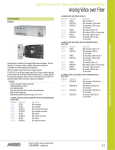
Operating Manual
iWAP103
Operating Manual
This page is intentionally left blank.
Document Number 321282 (See Last Page for Revision Details)
©2006 Extronics Limited. This document is Copyright Extronics limited.
Extronics reserve the right to change this manual and its contents without notice, the latest
version applies.
2
Operating Manual
Contents
1
2
3
4
5
6
7
8
Introduction.......................................................................................................... 4
Safety Information and Notes .............................................................................. 5
2.1
Storage of this Manual ................................................................................. 5
2.2
List of Notes ................................................................................................. 5
Installation and Setting-to-Work .......................................................................... 7
3.1
Installation .................................................................................................... 7
3.1.1
Removing the cover .............................................................................. 7
3.1.2
Fitting the cables ................................................................................... 8
3.1.3
Mains Power ....................................................................................... 11
3.1.4
POE/Ethernet Connection ................................................................... 11
3.1.5
Fibre Ethernet Input ............................................................................ 11
3.1.6
Earth Connection ................................................................................ 12
3.1.7
RS232/422/485 Wiring ........................................................................ 12
3.1.8
RS232/422/485 Dip Switch Configuration ........................................... 12
3.1.9
Thermostat Controls............................................................................ 14
3.1.10 Disassembly - Removing the PCB ...................................................... 16
3.1.11 Assembly – Fitting the PCB................................................................. 17
3.1.12 Fitting the 90° N-Type Connector................... ..................................... 18
3.1.13 Fitting the antenna mounting bracket .................................................. 23
3.1.14 Fitting the antennas to the bracket ...................................................... 25
3.1.15 General dimensions ............................................................................ 26
3.2
Setting to work............................................................................................ 27
Intended Purpose Usage................................................................................... 28
4.1
Transportation and Storage........................................................................ 28
4.2
Authorized Persons .................................................................................... 28
4.3
Cleaning and Maintenance......................................................................... 28
4.4
Safety Precautions ..................................................................................... 29
4.5
Cleaning and Maintenance Intervals .......................................................... 29
4.6
Aggressive substances and environments ................................................. 29
4.7
Exposure to external stresses .................................................................... 29
Technical Data .................................................................................................. 30
5.1
iWAP103 .................................................................................................... 30
Type Codes ....................................................................................................... 31
Certification ....................................................................................................... 32
Manual Revision ................................................................................................ 36
3
Operating Manual
1 Introduction
The iWAP103 Zone 1 Universal Access Point Enclosure is designed to allow the
deployment of wireless networks in hazardous areas. The concept allows
installation of equipment from leading WLAN vendors including Aeroscout, Meru,
Symbol, Cisco and Firetide. Each type of Access Point or RF transmitting device
is rigorously checked and tested by Extronics and/or a Notified Body to ensure
conformity to the ATEX requirements. This means that the user may select the
vendor of their choice when extending a WLAN to hazardous areas. However
equipment not already certified will require assessment to determine its
suitability.
To allow ease of installation to the end user the unit can be supplied via a
110/230VAC, or via IEEE802.3af POE providing the access point chosen is
compatible. An optional POE supply module allows the iWAP103 to
power up to two external devices such as IP cameras or additional
access points.
The iWAP103 has two RF outputs on N-type connectors allowing the connection
of two antennas for dual radio access points. These antennas must be certified
as Ex e increased safety devices (not included) such as the iANT100.
Optional features include surge arrestors for lightning suppression in outdoor
installations and fibre optic inputs for the Ethernet. Additionally the IWAP103 has
optional single or dual RS232/RS485/RS422 inputs, allowing these interfaces to
be transmitted over a WIFI link.
The iWAP103 has the option of adding heating to the enclosure which can be
used when the access point is required to be installed in temperatures as low as
-20 oC. The heaters may be independently configured to shut off above set
temperature thresholds. The protection board has two potentiometers fitted,
which allow the user to set the temperature at which the heaters will switch off,
and the temperature above which power to the access point is switched on. The
default setting is to allow the user to select a temperature of between 0oC and
40 oC above which the heaters are off, and temperatures between -20 oC and
20 oC above which the access point turns on. Note: These temperatures can be
altered on request when ordering.
The iWAP103 is housed in an Ex d (Flameproof) enclosure rated to IP66, and is
certified to;
II 2 G EEx d IIC T5 Ta 55oC Max, T6/Ta 40oC Max
Ex tD A21 IP66 T100oC@Ta55oC Max, T85oC@Ta40oC Max
.
4
Operating Manual
2 Safety Information and Notes
2.1 Storage of this Manual
Keep this user manual safe and in the vicinity of the device. All persons who have to work on
or with the device should be advised on where the manual is stored.
2.2 List of Notes
The notes supplied in this chapter provide information on the following.
• Danger / Warning.
o Possible hazard to life or health.
• Caution
o Possible damage to property.
• Important
o Possible damage to enclosure, device or associated equipment.
• Information
o Notes on the optimum use of the device
Warning
Installation only to be performed by skilled electricians and instructed
personnel in accordance with national legislation, including the relevant
standards and, where applicable, in accordance with IEC 79.17 on
electrical apparatus for explosive atmospheres.
Warning!
The iWAP103 must not be operated in Gas Zone 0, or Dust Zone 20
hazardous areas. Refer to the specification for ATEX certificate
information.
Warning!
Never open the enclosure in a hazardous area when the unit is
energized, never operate the internal electronics without correctly fitting
the lid and cable glands.
Important
The technical data indicated on the iWAP enclosure must be observed.
Important
Changes in the design and modifications to the equipment are not
permitted. This includes changing the pre installed Access Point.
Important
The iWAP103 shall be operated as intended and only in undamaged
condition.
Important
Only Ex e antennas which have been approved for use by Extronics may
be used with iWAP103
Important
Do not exceed the Effective Isotropic Radiated Power (EIRP) limit for the
country/region of operation
5
Operating Manual
Important
Do not exceed the Effective Isotropic Radiated Power (EIRP) for the gas
group in which the iWAP103 will be operating. The RF output of the
transceiver will vary depending on the hardware and antenna used.
IIC – 2W (+33dBm)
IIB – 3.5W (+35.4dBm)
IIC – 6W (+37.7dBm)
Caution
This assembly may weigh up to 15Kg depending on options fitted,
therefore ensure the assembly is mounted using suitable fixtures.
Caution
When powering the iWAP103 via POE it is not recommended to also
apply an external power supply to the protection board.
6
Operating Manual
3 Installation and Setting-to-Work
3.1 Installation
The iWAP 103 is simple to install and can be secured directly to a suitable surface
using the mounting holes on the Enclosure. Refer to 3.1.15
3.1.1
Removing the cover
Warning!
Never open the enclosure in a hazardous area when the unit is
energized, never operate the internal electronics without correctly fitting
the lid and cable glands.
Unscrew the grub screw and remove the enclosure lid by turning it anti-clockwise.
Grub
Screw
Figure 3.1
7
Four Mounting Lugs,
1 in each corner
Operating Manual
3.1.2
Fitting the cables
Depending on the configuration of the iWAP103, the connections for power and
communication will need to be terminated into the enclosure via the cable entries
shown in figure 3.2 (to be chosen by customer).
Gland 1
M25
Gland 2
Gland 4
M20
M20
Gland 3
M25
Gland 5
M25
Figure 3.2 – Cable Gland Holes
Cable glands are to be specified by the user when ordering, thread size is as
indicated above while the thread pitch of all holes is 1.5mm. Depending on the
configuration required these holes may be fitted with stopping plugs.
IMPORTANT!
All cables should be connected to the iWAP103 via a correct cable
gland suited to the cable used, fitted by a competent person.
Cable glands should be fitted in accordance with manufacturers
instructions. See iANT100 manual for instructions on fitting
iANT100 cable gland.
IMPORTANT!
Changes in the design and modifications to the equipment are not
permitted. This includes changing the factory installed access
point.
8
Operating Manual
Optional POE Module see
document 321313 for instructions
if this option has been chosen
Optional
Fibre Module
Connectors
Not User Serviceable
Surge
Arrestor/Ntype. 2.4
Surge
Arrestor/Ntype. 2.4
Surge
Arrestor/Ntype. 5.8
Surge
Arrestor/Ntype. 5.8
Thermostat
potentiometers
Dip Switches
For
RS232/422/
485
configurations
5
RS232/485/422
Inputs (Optional)
4
3
2
Ethernet Input on Ethernet Earth
screw plug/socket Input on Screw
terminals
RJ45
Connector
1
Mains
Input on
screw plug
socket
Figure 3.3 – iWAP103 Internal PCB View
Important
Only the input power connectors, DIP switches, Ethernet input
connectors, thermostat controls and N-type/surge arrestors, as indicated
in figure 3.3, are user configurable. Do not alter any other connections
inside the enclosure. The access point must not be changed or the
wiring altered.
9
Operating Manual
Ref
1
Connector
Pinout
Description
Mains Input
1
2
Pin 1 = Live
Pin 2 = Earth
Pin 3 = Neutral
3
Earth Screw Terminals
1
3
Ethernet input on RJ45
4
Ethernet input on
screw terminals
5
RS232/422/485 Inputs
2
1
8
1
9
10
18
Both screw terminals are
connected to earth, one
of the terminals should
be used to earth the
enclosure, the other
connector is a spare
This RJ45 socket
accepts a standard
8P8C plug for Ethernet
connection
Pin 1 = Tx +
Pin 2 = Tx Pin 3 = Rx +
Pin 4= POE in Pin 5= POE in Pin 6= Rx Pin 7 = POE +
Pin 8 = POE in +
Pin 1 = Tx +
Pin 2 = Tx Pin 3 = Rx +
Pin 4= POE in Pin 5= POE in Pin 6= Rx Pin 7 = POE +
Pin 8 = POE in +
Pins 1-9 are used for
RS232/422/485 module
1
Pins 10-18 are used for
RS232/422/485 module
2
See table 3.2 for
connections depending
on the configuration
required
Table 3.1 – Input Connector Pin Outs
Power can be supplied to the access point via a mains supply or a POE supply. The
POE supply is obtained directly from a POE enabled Ethernet input with the spare
wires of an 8 pin input used for the power supply.
Caution
When powering the iWAP103 via POE it is not recommended to also
apply an external power supply to the protection board.
10
Operating Manual
3.1.3
Mains Power
To connect the mains power, feed in a suitable cable through a suitable cable gland.
The PCB will be shipped with a socket fixed the PCB and a removable plug with
screw terminals screwed into it (Ref 1). Remove the plug from the socket by
unscrewing the screws at the two ends of the plug. Strip back the power cable and
ensure suitable crimps are used for each core of the cable; the cables core must
have a cross sectional area of at least 0.25mm2 and a maximum cross sectional area
of 2.5mm2. Place the crimped wire into the correct screw terminal as indicated in
table 3.1, and ensure the cable is securely screwed in place, then push the plug into
the socket and securely screw the two together.
3.1.4
POE/Ethernet Connection
Caution
Only make one Ethernet/POE connection, i.e. do not make a connection
to both the screw terminals and RJ45 connector!
To power the unit via POE a suitable POE supply is needed along with the Ethernet
input on (preferably) a cat-5 cable. The power is supplied on the spare pins of a
standard 8-way twisted pair wire - on pins 4,5,7 and 8, with the other pins used for
data transfer. The power can be supplied via the screw terminals (Ref 4) or the RJ45
connector (Ref 3) depending on the installer’s requirements and preferences.
To power the access point via POE using the RJ45 connector (Ref 3) ensure that an
8P8C connector is wired as stated in table 3.1. Feed the cable through a suitable
cable gland and then simply plug the cable into the socket and ensure the cable is
securely fastened.
To power the access point via POE using the screw terminals (Ref 4), feed the cable
through a suitable cable gland. Remove the plug from the socket by unscrewing the
screws at the two ends of the plug. Strip back the cable and ensure suitable crimps
are used for each core of the cable; the cables core must have a cross sectional area
of at least 0.14mm2 and a maximum cross sectional area of 1.5mm2. Place the
crimped wire into the correct screw terminal as indicated in table 3.1, and ensure the
cable is securely screwed in place, then push the plug into the socket and securely
screw the two together.
3.1.5
Fibre Ethernet Input
Important
When connecting the access point via a fibre connection do not use the
any of two Ethernet inputs of connectors Ref 3 or Ref 4.
To obtain greater wired link distances the iWAP103 can be shipped with an optional
fibre module. The fibre module will be connected directly to the access point, the user
should attach the fibre cable directly to the fibre module using a multimode fibre cable
on an ST connector.
11
Operating Manual
3.1.6
Earth Connection
The earth screw terminals allow the user to connect the enclosure to earth, this would
usually be done in the Extronics factory prior to shipping. There is also one spare
earth terminal. To connect to this earth terminal strip back the cable and ensure
suitable crimps are used; the cable’s core must have a cross sectional area of at
least 0.25mm2 and a maximum cross sectional area of 2.5mm2.
3.1.7
RS232/422/485 Wiring
If the optional RS232/422/485 module has been selected the serial input will need to
be connected to the screw terminals correctly. The pin out wiring connections will
depend on the interface you wish to use and is summarized below in table 3.2.
To make a connection to for the serial interface feed the cable through a suitable
cable gland. Remove the plug from the socket (Ref 5) by unscrewing the screws at
the two ends of the plug Strip back the serial cable and ensure suitable crimps are
used for each core of the cable; the cables core must have a cross sectional area of
at least 0.14mm2 and a maximum cross sectional area of 1.5mm2.
Pin (Module1/Module2)
RS232
RS422/RS485
1/10
2/11
3/12
4/13
5/14
6/15
7/16
8/17
9/18
TxD
DTR
RTS
RI
CTS
RxD
GND
DSR
DCD
TxD B +
TxD A RTS B +
RTS A RxD B +
RxD A GND
CTS B +
CTS A -
Table 3.2 Serial Pin Out Connections
3.1.8
RS232/422/485 Dip Switch Configuration
To correctly configure the iWAP103’s optional serial interface the dip switches on the
PCB need to be set correctly. Figure 3.x below shows an exploded view of the dip
switches. Use table 3.3 to correctly set the dip switches for the serial interface
required by the user.
12
Operating Manual
S7
S6
S8
S5
S1
S4
S2
S3
Figure 3.4 – iWAP103 Dip Switch Connections
Switch
Description
Mode
Module1/Module2
S1/S5
Select clock timing
S2/S6
Select RS232/422/485 mode
S3/S7
Mode Select
S4/S8
Line Termination
2.5ms
1=on 2=off 3=on
4.5ms
1=off 2=on 3=on
115/230Kbit/s mode
1=on 2=off 3=off
RS232 mode
1=on 2=off 3=off 4=off 5=off 6=on
R422 mode
1=on 2=off 3=off 5=off 6=on
RS485 4-wire mode
1=on 2=off 3=off 5=off 6=on
RS485 2-wire auto control mode
1=off 2=on 3=off 4=on 5=off 6=on
RS485 2-wire DTR control mode
1=off 2=off 3=on 4=off 5=on 6=off
RS232 mode
1=off 2=off 3 =off on 4=off
RS485 2-wire mode
1=off 2=on 3=off 4=off
RS485 4-wire mode
1=off 2=off 3=off 4=off
RS422 mode
1=off 2=on 3=off 4=off
RS232 mode
All off
RS485 2-wire mode
All on
RS485 4-wire mode
All on
RS422 mode
All on
13
Operating Manual
3.1.9
Thermostat Controls
Pot A Pot B
Figure 3.5 – Thermostat Potentiometers
If the optional heaters have been fitted, there are two potentiometers on the
iWAP103 protection board which allow the user to alter the temperature set points.
Pot A is used to set the access point switch on temperature, Pot B is used to control
the heater turn off temperature
If this option is fitted, the potentiometers will be factory set to;
Pot A = -20°C (Fully Left)
Pot B = 30°C (Fully Right)
The potentiometers have a turn radius of 270o when the potentiometer is turned fully
left the temperature will be set to a minimum. When the potentiometer is turned fully
right, the temperature is set to its maximum
By turning potentiometer A fully left the Access point will not turn on until the
temperature reaches -20oC. By turning Pot A fully right the AP will not turn on until
the temperature reaches 10oC
By turning potentiometer B fully left the heaters will not turn off until the temperature
reaches 0oC. By turning potentiometer B fully right the heaters will not turn off until
the temperature reaches 30oC.
14
Operating Manual
15
Operating Manual
3.1.10 Disassembly - Removing the PCB
Image
Description
Unscrew the enclosure lid.
Unscrew and disconnect the
RF connectors from the surge
arrestors or bulkheads. Unplug
all other connections to the
PCB. Make note of the
location of the connections
you remove to aid reassembly
Unscrew the 4 fixing screws
from the spacers below
16
Operating Manual
Tilt the front of the PCB
upwards and pull towards you.
Be careful when removing the
PCB from the enclosure as the
RF cables fitted under the
PCB may get damaged. Be
sure to take all necessary ESD
precautions to avoid damaging
sensitive components on the
PCB
Unscrew and disconnect the
RF connectors from the surge
arrestors or bulkheads on the
under side of the PCB. Be
careful not to bend the RF
cables too tightly, especially
by the connector, as this may
damage the cable.
Minimum bend radius of cable
= 3.18mm
3.1.11 Assembly – Fitting the PCB
To fit the PCB, follow the instructions found in section 3.1.10 of this manual in
reverse order;
• Connect RF connectors to surge arrestors or bulkheads on under side of the
PCB
• Carefully place the PCB inside the enclosure to sit on top of the spacers
• Screw the 4 fixing screws through the mounting holes on the PCB to the
spacers below
• Fit all necessary connections
• Screw in the enclosure lid securely
17
Operating Manual
3.1.12 Fitting the 90° N-Type Connector
Image
Description
If using the Extronics
iANT100 series of antenna’s,
please follow the procedure
for making the
CR-UB-NP-16-M20 gland*
as instructed in the iANT100
manual.
If using another antenna, be
sure to follow the
manufacturer’s instruction as
to fitting the cable gland.
*CR-UB-NP-16-M20 is the
recommended cable gland
for use with the iANT100
antenna
In order to fit an N-Type
connector, cut off the
connector and slide onto
cable approximately 30mm of
heat-shrink sleeving and the
ferulle supplied with the
connector.
Strip the cable as shown
leaving;
• 8mm of exposed
shielding
• 7mm of exposed
dielectric insulator
• 4mm of exposed core
18
Operating Manual
Using a soldering iron, tin the
core of the cable
Place the 90° N-Type
connector on the end of the
connector such that the
dielectric and core sit inside
the connector and the shield
is outside of the connector
Remove the cap from the top
of the connector. Apply solder
such that the centre pin of the
connector and the core of the
cable are bonded.
19
Operating Manual
Slide the ferrule to the base of
the N-Type connector and
using the appropriate tooling,
crimp the cable in place.
Make sure that the cable and
the connector are firmly
secured.
Universal frame crimp tool
RS Stock No. 848-391
Universal frame die setRG58/59 cables
RS Stock No. 848-436
Slide the sleeving to the base
of the connector so that it
covers the crimp. Apply heat
to the sleeving until it has fully
taken shape of the
components it surrounds.
Must be done in accordance
to heat-shrink manufacturer’s
instruction
Re-fit cap to connector
20
Operating Manual
Push the connector through
the appropriate M25 cable
entry on the iWAP103
enclosure. Be careful when
doing this as not to damage
the threads.
Fit the connector to the NType bulkhead fitted to the
PCB
Thread the M25 to M20
reducer to the enclosure.
Hand tighten and using a
wrench, tighten by another
quarter turn.
21
Operating Manual
Fit entry body into the reducer
previously fitted. Handtighten, then using a wrench
tighten a further ½ turn
Fit the remainder of the gland
to the entry body using the
union nut of the cable gland.
Hand-tighten, then using a
wrench tighten a further ½
turn
Ensure all components are
fitted securely
22
Operating Manual
3.1.13 Fitting the antenna mounting bracket
Image
Description
Supplied fixings;
2 off M5 nyloc nut
2 off M5 x 16mm grub screw
2 off M5 plain washer
2 off M5 nylon washer
Apply Loctite along the thread
of the grub screw
(243 – Thread lock or 270 stud lock)
Using an allen key (2.5 ATF),
thread the grub screws into
the entries shown until they
bottom
23
Operating Manual
Once the grub screws are
fitted, place the nylon
washers onto the grub
screws
Place the antenna bracket
(iANTMB02) onto the grub
screws
Using the plain washer and
nyloc nut, fit the bracket
securely
24
Operating Manual
3.1.14 Fitting the antennas to the bracket
Image
Description
Fixing kit supplied with each
antenna;
1 off M6 x 12mm pozi panhead screw
1 off M6 spring washer
Using the screw and washer,
fit the antenna to the bracket
using the appropriate hole
Tighten screws so the
antennas are fitted securely
25
Operating Manual
IMPORTANT!
Only connect antenna cables to the N-Type or Surge Arrestor.
Never connect the antennas to the access point directly.
IMPORTANT!
All cables should be connected to the iWAP103 via a correct cable
gland, fitted by a competent person.
IMPORTANT!
Only Ex e antennas which have been approved for use by
Extronics may be used with iWAP103
IMPORTANT!
Do not exceed the Effective Isotropic Radiated Power (EIRP) for
the country/region of operation
IMPORTANT!
Do not exceed the Effective Isotropic Radiated Power (EIRP) for
gas group the iWAP103 will be operating in. The RF output of the
transceiver will vary depending on the hardware used.
IIC – 2W (+33dBm)
IIB – 3.5W (+35.4dBm)
IIC – 6W (+37.7dBm)
3.1.15 General dimensions
26
Operating Manual
3.2 Setting to work
•
•
Once all cables are connected, refit the enclosure lid by rotating clockwise
700N/mm2, once the lid is closed ensure the grub screw is tightened.
Refer to the original manufacturer’s instructions for detailed information on
setting the hardware to work correctly in software. The RS232/422/485 com
server uses a W&T 58631 device.
Note!
Ensure the lid is secure, correct cable glands are fitted and the
unit device correctly wired and earthed for the particular
application
Note!
Ensure that the threaded sections of the enclosure lid and body
assembly are clean and undamaged. Also check the IP O’ring is
clean and undamaged before fitting the lid.
27
Operating Manual
4 Intended Purpose Usage
Important
Before setting the units to work, read the technical documentation
carefully.
Important
The latest version of the technical documentation or the corresponding
technical supplements is valid in each case.
The iWAP103 is built using modern components and is extremely reliable in
operation; however it must only be used for its intended purpose. Please note that
the intended purpose also includes compliance with the instructions issued by the
manufacturer for installation, setting up and service.
Any other use is regarded as conflicting with the intended purpose. The manufacturer
is not liable for any subsequent damage resulting from such inadmissible use. The
user bears the sole risk in such cases.
4.1 Transportation and Storage
All iWAP103 devices must be so transported and stored that they are not subjected
to any excessive mechanical stresses.
4.2 Authorized Persons
Only persons trained for the purpose are authorized to handle the iWAP103; they
must be familiar with the unit and must be aware of the regulation and provisions
required for explosion protection as well as the relevant accident prevention
regulations.
4.3 Cleaning and Maintenance
The iWAP103 and all its components require no maintenance. All work on the
iWAP103 by personnel who are not expressly qualified for such activities will cause
the Ex approval and the guarantee to become void.
28
Operating Manual
4.4 Safety Precautions
Important
For the installation, maintenance and cleaning of the units, it is
absolutely necessary to observe the applicable regulations and
provisions concerned with explosion protection (EN 50014, EN 6007914:2003) as well as the Accident Prevention Regulations.
4.5 Cleaning and Maintenance Intervals
The cleaning intervals depend on the environment where the system is installed.
4.6 Aggressive substances and environments
The iWAP103 is not designed to come into contact with aggressive substances or
environments, please be aware that additional protection may be required.
4.7 Exposure to external stresses
The iWAP103 is not designed to be subjected to excessive stresses e.g. vibration,
heat, impact. Additional protection is required to protect against these external
stresses.
The iWAP103 will require additional protection if it is installed in a location where it
may be subjected to damage.
29
Operating Manual
5 Technical Data
5.1 iWAP103
Power Supply
Universal 90-264VAC or IEEE802.11af POE
Maximum Power Consumption
Basic configuration 19W
With RS485 modules 24W
With POE output module 55W
With heating 155W
Enclosure Material
LM6 marine grade alloy with epoxy paint coat
Ingress Protection
IP66
Weight
Approx 15Kg, hardware dependent
Dimensions
300 x 280 x 200 mm (w x h x d)
Environmental
Ambient temperature (T5/T6); -20ºC/-10ºC to
40ºC/55ºC (note this depends on the internal
hardware used)
Relative humidity; 0 to 95%, non condensing
Input Connections
10/100BaseT Ethernet on RJ45 socket and screw
terminals
115V/230VAC input option on screw terminals
Multimode fibre input option on ST connectors
POE output option on screw terminals and RJ45
sockets
RS232/485/422 IO on screw terminals
Note that connectors may be specified as an option
in the ordering data
Output Connections
Up to four RF outputs on Ex d cable glands with
optional lightning arrestors
Antennas
To be used with up to four Ex e antennas (not
included) e.g. Extronics iANT100 series
ATEX Certification
II 2 G EEx d IIC T5 Ta 55oC Max T6/Ta 40oC Max
Ex tD A21 IP66 T100oC@Ta55oC Max
T85oC@Ta40oC Max
30
Operating Manual
6 Type Codes
iWAP103 - Universal Zone 1 Access Point iWAP103-[#1]-[#2]-[#4]-[#5]-[#6]-[#7]-[#8]-[#9]-[#11]-[#12]
Specify option [#1] - Wireless Network Hardware
Hardware supplied by customer*
Hardware supplied by Extronics
0
1
*Extronics can supply the certified wireless network hardware ,alternatively you may wish to “free issue” one of the already
certified solutions so that we can factory fit it (see option #2 for certified hardware list).
Specify option [#2] - Type Of Wireless Network Hardware (Max operating temperature listed in brackets, POE/Mains only
is the iWAP103 with no additional modules attached, Mains + modules is the maximum temperature with additional modules
included. The minimum temperature range is also listed, the heater option will allow the temperature range of the AP’s stated
as 0oC, to be operated to a temperature of –20oC.)
Cisco AP1231 Access Point
Cisco AP1242 Access Point
Cisco AP1242 LAP Light Access Point
Symbol AP300 Access Port Single Radio
Symbol AP5131 Access Point Single Radio
Symbol AP300 Access Port Dual Radio
Symbol AP5131 Access Point Dual Radio
Meru AP200
Meru AP150
Cisco AP1232 Access Point
Cisco AP1231 LWAPP Light Access Point
Cisco AP1232 LWAPP Light Access Point
AirMagnet A5020 Sensor
Firetide Hotport 4500 Access Point
Aruba AP60
Aruba AP61
Aruba AP70
Acksys WLG-LINK-OEM-RJ-EVAL Access Point
(POE/Mains Only = 45oC, Mains + Modules = 40oC) (Min. = -20oC)
(POE/Mains Only = 45oC, Mains + Modules = 40oC) (Min. = -20oC)
(POE/Mains Only = 45oC, Mains + Modules = 40oC) (Min. = -20oC)
(POE/Mains Only = 40oC, Mains + Modules = 35oC) (Min. = -20oC)
(POE/Mains Only = 40oC, Mains + Modules = 35oC) (Min. = -20oC)
(POE/Mains Only = 40oC, Mains + Modules = 35oC) (Min. = -20oC)
(POE/Mains Only = 40oC, Mains + Modules = 35oC) (Min. = -20oC)
(POE/Mains Only = 40oC, Mains + Modules = 35oC) (Min. = 0oC)
(POE/Mains Only = 55oC, Mains + Modules = 50oC) (Min. = 0oC)
(POE/Mains Only = 45oC, Mains + Modules = 40oC) (Min. = -20oC)
(POE/Mains Only = 45oC, Mains + Modules = 40oC) (Min. = -20oC)
(POE/Mains Only = 45oC, Mains + Modules = 40oC) (Min. = -20oC)
(POE/Mains Only = 40oC, Mains + Modules = 35oC) (Min. = 0oC)
(POE/Mains Only = 40oC, Mains + Modules = 35oC) (Min. = 0oC)
(POE/Mains Only = 40oC, Mains + Modules = 35oC) (Min. = 0oC)
(POE/Mains Only = 40oC, Mains + Modules = 35oC) (Min. = 0oC)
(POE/Mains Only = 40oC, Mains + Modules = 35oC) (Min. = 0oC)
(Mains Only = 55oC, Mains + Modules = 55oC)
(Min. = -20oC)
3
6
7
8
9
10
11
13
14
15
16
18
19
22
23
24
25
26
Specify option [#4] - Power Supply
Universal 90-264VAC (If heater option [#8] selected the unit is not universal voltage, either 115VAC or 230VAC)
IEEE802.3af compliant Power-Over-Ethernet
AC
POE
Specify option [#5] - Ethernet Connection
10/100BaseT Ethernet on CAT5 copper
Multimode 10/100BaseFX fibre with ST connector
C
F
Specify option [#6] - 2 x Antenna Lightning Protection For Option [#2]
No Lightning Protection Fitted, 2xN-Type Bulkheads fitted for antenna connection
Lightning Protection Fitted
N
S
Specify option [#7] - 2 x Additional Antenna Lightning Protection For Option [#2]
No Lightning Protection Fitted, 2xN-Type Bulkheads fitted for antenna connection
Lightning Protection Fitted
N
S
Nothing Fitted
B
Specify option [#8] - Enclosure Heating (not compatible with universal 90-264VAC or POE supplies)
No enclosure heating
N
115VAC enclosure heating
230VAC enclosure heating
H1
H2
Specify option [#11] - RS232/RS485/RS442 interface
No RS232/RS485/RS422 interface fitted
1 x RS232/RS485/RS422 interface fitted
2 x RS232/RS485/RS422 interfaces fitted
N
1
2
Specify option [#12] - Dual IEEE802.3af POE outputs (not compatible with POE supply)
No POE outputs
Two POE outputs fitted
N
P
31
Operating Manual
7 Certification
32
Operating Manual
33
Operating Manual
34
Operating Manual
35
Operating Manual
8 Manual Revision
Revision
01
02
03
04
Description
Initial Release
Added Compliance Information
Added Dis-Assembly Instructions / Updated
Thermostat Controls / RS485 Pins
Descriptions / Added complete ATEX
certificate / added EC declaration of
conformity
Added additional installation instructions
36
Date
7/04/2008
15/10/2008
10/12/08
By
AJR
AJR
JE / AJR
16/02/09
JE