1
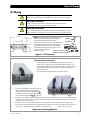
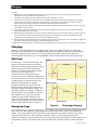
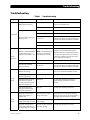
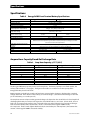
EnergyCell RE Front Terminal Battery Owner’s Manual YOUR Khd<WKtZ DISTRIBUTOR SOLIGENT 800-967-6917 www.soligent.net About OutBack Power Technologies OutBack Power Technologies is a leader in advanced energy conversion technology. Our products include true sine wave inverter/chargers, maximum power point tracking charge controllers, and system communication components, as well as circuit breakers, batteries, accessories, and assembled systems. Contact Information Telephone: +1.360.435.6030 +1.360.618.4363 (Technical Support) +1.360.435.6019 (Fax) Mailing Address: (North America) OutBack Power Technologies 5917 – 195th Street N.E., #7 Arlington, WA 98223 USA E-mail: [email protected] Web Site: www.outbackpower.com Address: Sales, Marketing, & Warranty 6115 – 192nd Street NE Arlington, WA 98223 USA Disclaimer UNLESS SPECIFICALLY AGREED TO IN WRITING, OUTBACK POWER TECHNOLOGIES: (a) MAKES NO WARRANTY AS TO THE ACCURACY, SUFFICIENCY OR SUITABILITY OF ANY TECHNICAL OR OTHER INFORMATION PROVIDED IN ITS MANUALS OR OTHER DOCUMENTATION. (b) ASSUMES NO RESPONSIBILITY OR LIABILITY FOR LOSS OR DAMAGE, WHETHER DIRECT, INDIRECT, CONSEQUENTIAL OR INCIDENTAL, WHICH MIGHT ARISE OUT OF THE USE OF SUCH INFORMATION. THE USE OF ANY SUCH INFORMATION WILL BE ENTIRELY AT THE USER’S RISK. Warranty Summary OutBack Power Technologies Inc. warrants that the products it manufactures will be free from defects in materials and workmanship for a period of two (2) years subject to the conditions set forth in the warranty detail, found at the end of this manual. OutBack Power Technologies cannot be responsible for system failure, damages, or injury resulting from improper installation of their products. Notice of Copyright EnergyCell RE Front Terminal Battery Owner’s Manual © November 2011 by OutBack Power Technologies. All Rights Reserved. Trademarks OutBack Power is a registered trademark of OutBack Power Technologies. Date and Revision November 2011, Revision A Part Number 900-0127-01-00 Rev A Important Safety Instructions Important Safety Instructions READ AND SAVE THESE INSTRUCTIONS! This manual contains important safety instructions for the EnergyCell RE battery. Read all instructions and cautionary markings on the EnergyCell RE battery and on any accessories or additional equipment included in the installation. Failure to follow these instructions could result in severe shock or possible electrocution. Use extreme caution at all times to prevent accidents. WARNING: Hazard to Human Life This type of notation indicates that the hazard could be harmful to human life. CAUTION: Hazard to Equipment This type of notation indicates that the hazard may cause damage to the equipment. IMPORTANT: This type of notation indicates that the information provided is important to the installation, operation and/or maintenance of the equipment. Failure to follow the recommendations in such a notation could result in voiding the equipment warranty. Audience This manual is intended for use by anyone required to install and operate this battery. Be sure to review this manual carefully to identify any potential safety risks before proceeding. The owner must be familiar with all the features and functions of this battery before proceeding. Failure to install or use this battery as instructed in this manual can result in damage to the battery that may not be covered under the limited warranty. General Safety WARNING: Limitations on Use This equipment is NOT intended for use with life support equipment or other medical equipment or devices. CAUTION: Equipment Damage Only use battery components or accessories recommended or sold by OutBack Power Technologies or its authorized agents. IMPORTANT: Do not attempt to install this battery if it appears to be damaged in any way. Contact the vendor if the battery was received in a damaged condition. If the battery was damaged during use, see the Warranty section for instructions. 900-0127-01-00 Rev A 1 Important Safety Instructions Personal Safety WARNING: Personal Injury This battery weighs in excess of 115 lbs (52 kg). Use safe lifting techniques when lifting this equipment as prescribed by the Occupational Safety and Health Association (OSHA) or other local codes. Lifting machinery may be recommended as necessary. Wear appropriate protective equipment when working with batteries, including eye or face protection, acid-resistant gloves, an apron, and other items. Use safety equipment as prescribed by the Occupational Safety and Health Association (or other local codes) when working on this or related equipment. Examples include steel-toed safety boots, safety hard hats, and other items. Use appropriate safety practices when working with electrical equipment (remove all jewelry, use insulated tools, wear cotton clothing, etc.) Never work alone when installing or servicing this equipment. Have someone nearby that can assist if necessary. Wash hands after any contact with the lead terminals or battery electrolyte. Battery Safety WARNING: Explosion, Electrocution, or Fire Hazard 2 Ensure the cables are properly sized based on the requirements of devices which use these batteries. Failure to size the cables properly can result in a fire hazard. Ensure clearance requirements are strictly enforced around the batteries. Keep plenty of fresh water and soap nearby in case battery acid contacts skin, clothing, or eyes. Wear complete eye and clothing protection when working with batteries. Avoid touching bare skin or eyes while working near batteries. If battery acid contacts skin or clothing, wash immediately with soap and water. If acid enters the eye, immediately flood it with running cold water for at least 20 minutes and get medical attention as soon as possible. Never charge a frozen battery. If a battery must be removed, always remove the grounded terminal from the battery first. Make sure all devices are de-energized or disconnected to avoid causing a spark. Do not perform any servicing other than that specified in the installation instructions unless qualified to do so and have been instructed to do so by OutBack Technical Support personnel. When connecting cables from the inverter to the battery terminals, ensure the proper polarity is observed. Connecting the cables incorrectly can damage or destroy the equipment and void the warranty. Use only the recommended cable sizes (or greater) for AC and DC conductors in compliance with local codes. Ensure all conductors are in good condition. Do not operate the system with damaged or substandard cabling. Ensure the area around the batteries is well ventilated and clean of debris. Never smoke, or allow a spark or flame near, the batteries. Always use insulated tools. Avoid dropping tools onto batteries or other electrical parts. Insulate batteries as appropriate against freezing temperatures. A discharged battery will freeze more easily than a charged one. 900-0127-01-00 Rev A Important Safety Instructions Required Resources This product is required to be installed according to pertinent safety codes and standards. If installed in the United States, wiring practices must meet the requirements of the National Electrical Code (NEC). If installed in Canada, wiring practices must meet the requirements of the Canadian Electrical Code. National Electrical Code (NEC)/NFPA 70, Current Edition Canadian Electrical Code, C22.1, Current Edition EnergyCell RE Material Safety Data Sheet Additional Resources These references may be used when installing this equipment. Depending on the nature of the installation, it may be highly recommended to consult these resources. National Electrical Code (NEC)/NFPA 70 Handbook, Current Edition International Building Code (IBC), Current Edition Photovoltaic Power Systems and the 2005 National Electrical Code: Suggested Practices Institute of Electrical and Electronics Engineers (IEEE) guidelines: IEEE 450, IEEE 484, IEEE 1184, IEEE 1187, IEEE 1188, IEEE 1189, IEEE 1491, IEEE 1578, IEEE 1635, and IEEE 1657 (various guidelines for design, installation, maintenance, monitoring, and safety of battery systems) Recycling Information IMPORTANT: Recycle Electronics and Batteries Batteries are considered hazardous waste and must be recycled according to local jurisdiction. OutBack EnergyCell batteries are 100% recyclable. The following web sites and phone numbers provide additional information for recycling batteries. Earth 911, USA Web site: Address: Phone: http://www.Earth911.com 14646 N. Kierland Blvd., Suite 100 Scottsdale, AZ 85254 +1.480.337.3025 (direct) Keep America Beautiful, USA Web site: Email: Address: Phone: Fax: http://www.kab.org/ [email protected] 1010 Washington Boulevard Stamford, CT 06901 +1.203.659.3000 (Main number) +1.203.659.3001 National Institute of Recyclers, Mexico Web site: Email: Phone: Fax: 900-0127-01-00 Rev A http://www.inare.org.mx/ [email protected], [email protected] +1.55.57.85.9160 +1.55.57.84.1279 3 Table of Contents Table of Contents Important Safety Instructions ........................................................................1 Audience .................................................................................................................................................................................1 Required Resources .............................................................................................................................................................3 Additional Resources ..........................................................................................................................................................3 Recycling Information ........................................................................................................................................................3 EnergyCell RE Battery ....................................................................................5 Welcome to OutBack Power Systems ...........................................................................................................................5 Materials Required ...............................................................................................................................................................5 Tools (use only insulated tools)...................................................................................................................................................5 Accessories.........................................................................................................................................................................................5 Storage and Environment Requirements....................................................................................................................6 Temperatures ....................................................................................................................................................................................6 Self-Discharge and Freshening ...................................................................................................................................................6 Capacity ...................................................................................................................................................................................6 State of Charge......................................................................................................................................................................7 System Layout .......................................................................................................................................................................7 Battery Configurations ...................................................................................................................................................................7 DC Wiring ................................................................................................................................................................................9 Charging ............................................................................................................................................................................... 10 Bulk Stage.........................................................................................................................................................................................10 Absorption Stage ...........................................................................................................................................................................10 Float Stage........................................................................................................................................................................................11 Notes on Charging.........................................................................................................................................................................11 Temperature Compensation......................................................................................................................................................12 Periodic Evaluation and Maintenance....................................................................................................................... 12 24-Hour Open-Circuit Test..........................................................................................................................................................12 25-Amp Capacity Test...................................................................................................................................................................12 Troubleshooting................................................................................................................................................................ 13 Specifications...................................................................................................................................................................... 14 Ampere-Hour Capacity Based On Discharge Rate..............................................................................................................14 Product Registration ...................................................................................15 Warranty....................................................................................................17 2-Year Limited Warranty for EnergyCell RE Products........................................................................................... 17 How to Arrange for Warranty Service ........................................................................................................................ 17 Troubleshooting.............................................................................................................................................................................17 4 900-0127-01-00 Rev A EnergyCell RE Battery Welcome to OutBack Power Systems Thank you for purchasing the EnergyCell RE battery. This product is a valve-regulated lead-acid (VRLA) battery. This type of battery incorporates an absorbent glass mat and pasted lead-calcium-tin plates. It is intended for use in backup, off-grid, and renewable energy (RE) applications. The EnergyCell RE is designed to provide long, reliable service with minimal maintenance. Intended for use with all OutBack inverters, charge controllers, and other devices that require the use of deep-cycle batteries. High-density pasted plates for high cycle life Lead-calcium-tin alloy plates for long life in both cycling and float applications High recharge efficiency Compact footprint for higher energy density Thermally welded case-to-cover bond to eliminate leakage 100% recyclable UL-recognized component Figure 1 EnergyCell RE Battery Materials Required Tools (use insulated tools only) Torque wrenches Voltmeter Accessories Interconnect bar Hardware Terminal cover 22.1” (55.9 cm) 4.9” (12.6 cm) 11.1” (28.3 cm) EnergyCell 200RE dimensions are listed on page 14. Figure 2 EnergyCell 170RE Battery Dimensions 900-0127-01-00 Rev A 5 Configurations Storage and Environment Requirements Temperatures The battery should not be operated in an environment where the average ambient temperature exceeds 85°F (27°C). The peak temperature of the operating environment should not exceed 110°F (43°C) for a period of more than 24 hours. High operating temperatures will shorten a battery’s life (see page 7). The battery should never be allowed to freeze, as this will damage it and could result in leakage. The battery should not be subjected to temperature variations of more than 5°F (3°C). This will lead to unbalanced voltages between multiple batteries (or between cells in one battery, if it is subjected to a temperature differential). These batteries should be stored in a cool, dry location. They should be placed in service as soon as possible after receiving them. The recommended temperature for storage is 77°F (25°C). However, a range of 60°F (16°C) to 80°F (27°C) is acceptable. Self-Discharge and Freshening The EnergyCell RE battery comes fully charged, but will discharge itself over time. Higher storage temperatures increase the rate of self-discharge. Figure 3 compares self-discharge with temperatures. When fully charged, the battery’s natural or “rest” voltage is 25% approximately 12.8 Vdc. It should be given a “freshening” 20% charge (see page 11) if its rest voltage drops below 12.5 Vdc per battery (2.08 Vdc per cell). A battery should not be used 15% if its rest voltage is 12.0 volts or lower upon delivery. 10% Contact the vendor upon receiving a battery in this state. 5% If left in storage, a battery must be given a freshening charge every six months when stored at 77°F (25°C). 0% The charge should be every three months if stored at 60°F 70°F 80°F 90°F 100°F 110°F 120°F 130°F 21°C 21°C 27°C 32°C 38°C 43°C 49°C 54°C temperatures of up to 92°F (33°C). If stored in higher Temperature temperatures, the charge should be every month. The EnergyCell RE battery should never be permitted to Figure 3 Self-Discharge Effects self-discharge below 75% of its capacity. This is highly detrimental and will shorten battery life. (This is not the same as discharging under load. See page 7.) Monthly Self-Discharge Capacity % of Capacity The EnergyCell RE capacity is given in ampere-hours (amp-hours). This is a current draw which is multiplied by the duration of current flow. A draw of X amperes for Y hours equals an accumulation of XY amp-hours. Because the battery’s chemical reaction constantly releases energy, it tends to replenish its own charge to a minor degree. Smaller loads will deplete the batteries less than larger loads because of this constant replenishment. This means 100 that effectively the battery has more capacity under lighter loads. 95 90 For example, if the EnergyCell 170RE is discharged at the 48-hour 85 rate (a load expected to drain 100% of its capacity in 48 hours), it 80 will be measured to have 163.9 amp-hours. However, at the 4-hour 75 70 rate, a heavier load, only 120.6 amp-hours will be measured. (See 65 Table 3 on page 14 for discharge rates and amp-hours.) 60 The EnergyCell RE models are named after their capacity at the 55 100-hour rate: 170 and 200 amp-hours respectively. The capacity also varies with temperature. Figure 4 shows changes in capacity at various temperatures. Two curves are graphed for different current rates: one indicating an amperage measurement equal to 1/100 of overall battery capacity (C/100), the other showing an amperage of 1/20 of capacity (C/20). 6 -22°F -4°F 14°F -30°C -20°C -10°C 32°F 0°C 50°F 10°C 68°F 86°F 104°F 20°C 30°C 40°C Temperature Figure 4 Capacity Effects 900-0127-01-00 Rev A State of Charge State of Charge 100 90 % of Expected Life The battery state of charge (SOC) can be determined by two methods. One is to measure its voltage. This is accurate only if the batteries are left at rest (no charging or loads) for 24 hours at room temperature (77°F or 25°C). If these conditions are not met, then voltage checks may not yield usable results. If they are met, then on average, a battery at 12.84 Vdc will be at 100% SOC (12.24 Vdc represents roughly 50% SOC). The more accurate method is to use a battery monitor such as the OutBack FLEXnet DC. Using a sensor known as a shunt, the monitor observes the current through the battery. It keeps a total of amp-hours lost or gained by the battery and can give accurate SOC readings. 80 70 60 50 40 30 20 70°F 80°F 90°F 100°F 110°F 120°F 130°F 21°C 27°C 32°C 38°C 43°C 49°C 54°C Temperature The EnergyCell RE battery is designed for a life of many discharge/charge Figure 5 Battery Life cycles. For optimal battery life, it is recommended not to discharge below 70% SOC (30% depth of discharge) on a regular basis. The battery should never be discharged below 50% of its capacity, as this will significantly shorten its life. If operated in the recommended range, the battery will typically have a life of hundreds of cycles. With consistently lighter discharge, the battery may have thousands of cycles. (This can be affected by temperature. Figure 5 shows the effect of ambient temperature on battery life.) System Layout CAUTION: Fire Hazard Failure to ventilate the battery compartment can potentially result in the buildup of hydrogen gas, which is explosive. The battery enclosure or room must be well-ventilated. This will protect against the accidental buildup of hydrogen gas. The EnergyCell RE battery is sealed and does not normally emit noticeable amounts of gas. However, in the event of accidental leakage, the enclosure must not allow gas to become concentrated. The battery enclosure or room must have adequate lighting. This is necessarity to read terminal polarity, identify cable color, and view the physical state of the battery as required. The battery should be installed with a minimum 36” (91.4 cm) clearance in front. This allows access for testing, maintenance, or any other reasons. If multiple batteries are installed, they should have a minimum of ½” (12.7 mm) clearance on either side. Battery Configurations Load – Load + Series string (24 Vdc) Load – Load + Series string (48 Vdc) Batteries are placed in series (negative to positive) for additive voltages. Batteries in series are known as a “string”. A string of two EnergyCell RE batteries has a nominal voltage of 24 Vdc and can be used for 24-volt loads. A string of four has a nominal voltage of 48 Vdc. Other voltages are possible. However, batteries in series do not have additive amp-hours. A single string of any voltage (as shown above) has the same amp-hours as a single battery. When replacing batteries, a new battery should not be placed in series with a string of old batteries, as this will cause severe stress and shorten the life of all batteries. All batteries in a string should be replaced at the same time. Figure 6 Series String Configurations 900-0127-01-00 Rev A 7 Configurations Batteries are placed in parallel (positive to positive, negative to negative) for additive amp-hour capacity. Three batteries in parallel have three times the amp-hours of a single battery. However, batteries in parallel do not have additive voltages. A single set of batteries in parallel (as shown below) have the same voltage as a single battery. Series/parallel strings Load Bus – Load Bus + It is not recommended to place more than three batteries or three strings in parallel. Imbalances between batteries will reduce the efficiency and shorten the life of all batteries. Load Bus – Parallel batteries Load Bus + Figure 7 Parallel and Series/Parallel String Configurations Batteries are placed in both series and parallel for both additive voltage and amp-hour capacity. Series strings placed in parallel have the same nominal voltage as each string. They have the same amp-hour capacity of each string added together. Two parallel strings of two EnergyCell RE batteries in series have a nominal voltage of 24 Vdc, twice the nominal voltage. (See the illustration on the right side of Figure 7.) They also have double the amp-hour capacity of a single battery. Two parallel strings of four batteries in series (see Figure 8) have a nominal voltage of 48 Vdc at double the amp-hour capacity of a single battery. In a series-parallel bank, it is not recommended to connect the load to the positive and negative terminals of a single string. Due to cable resistance, this will tend to put more wear on that string. Instead, it is recommended to use “reverse-return” or “cross-corner” wiring, where the positive cable is connected to the first string and the negative to the last. This will allow current to flow evenly among all strings. This method is shown in both figures. Figure 8 Series/Parallel String Configuration 8 900-0127-01-00 Rev A State of Charge DC Wiring CAUTION: Equipment Damage Never reverse the polarity of the battery cables. Always ensure correct polarity. CAUTION: Fire Hazard Always install a circuit breaker or overcurrent device on the DC positive conductor for each device connected to the batteries. CAUTION: Fire Hazard Never install extra washers or hardware between the mounting surface and the battery cable lug or interconnect. The decreased surface area can build up heat. 4.9” (12.6 1.2” (3.0 cm) NOTE: To avoid corrosion, use plated lugs on cable terminations. When multiple cables are being terminated, use plated terminal bus bars. ¼”-20 UNC Bolt Lock Washer 2.6” (6.6 cm) 1.0” (2.6 cm) Install cable lug (or interconnect), nuts, and washers in the order illustrated. The lug or interconnect Flat Washer should be the first item installed. It should make solid contact with the mounting surface. Do not install hardware in a different Cable Lug (or Interconnect) order than shown. Battery Terminal Surface Figure 9 DC Terminals To make the DC connections: 1. If installing batteries in the OutBack EnergyCell RE battery rack or a similar cabinet, always begin with the lowest shelf for stability. Four EnergyCell RE batteries can be placed on one shelf. All batteries should be placed with terminals facing to the front. Remove and save the terminal protectors. 2. Clean and lightly brush all terminals and contact surfaces. 3. In normal configurations, the battery on the far right will be the positive (+) output for that . string. This battery should be designated Proceeding to the left, adjacent batteries in that , , and so on. string should be designated 4. If more than one string is present, designate the first string as A, the second as B, and so on. This should be done regardless of whether the strings are on the same shelf or higher shelves. Number the batteries in subsequent strings just as was done in step 3. Install series connections using the interconnect and hardware that was supplied with each battery. The interconnect should connect from the negative (left) side of battery 1 to the positive (right) side of battery 2 as shown above. Tighten interconnect hardware “hand tight” only. Continued on the next page... 5. Figure 10 Connecting Batteries 900-0127-01-00 Rev A 9 Charging (continued) 6. 7. 8. 9. 10. 11. 12. 13. Repeat the process as appropriate for batteries 2, 3, and any others in the string. Connect the proper number of batteries in series for the nominal voltage of the load. If multiple series strings will be used, repeat this process for strings B, C, and so on. Install parallel connections. Parallel connections are made from the positive terminal of one battery or string to the positive of the next; negative connections are made similarly. (See Figure 7.) External cables or bus bars must be provided. The interconnect included with the battery cannot make parallel connections. Use a digital voltmeter (DVM) to confirm the nominal system voltage and polarity. Confirm that no batteries or strings are installed in reverse polarity. Install cables or bus bars for DC loads. Size all conductors as appropriate for the total loads. See the manual for the EnergyCell RE Battery Rack if necessary. Before making the final battery connection, ensure the main DC disconnect is turned off. If this is not possible, then do not make the final connection within the battery enclosure. Instead, make it at the load or elsewhere in the cable system so that any resulting spark does not occur in the battery enclosure. Once hardware is installed and batteries are properly aligned, torque all connections to 110 in-lb (12.4 Nm). Lightly coat the surfaces with battery terminal grease and reinstall the terminal covers. Make the final DC connections. Commission (“freshen”) the batteries with a full recharge. (See below; also see page 11.) Charging Batteries in renewable applications are usually charged using a “three-stage” charging cycle: bulk stage, absorption stage, and float stage. Most OutBack chargers follow this algorithm. However, not all chargers are designed or programmed the same way. The settings should be checked and changed to match the recommendations below if necessary. Contact OutBack Technical Support before using other charger types. Bulk Stage The bulk stage is a constant-current stage. The charger’s current is maintained at a constant high level. The battery voltage will rise as long as the current continues to flow. Each battery model has a recommended maximum current limit (see Table 2 on page 14). It is recommended not to exceed this limit. At excessive current rates, the battery’s efficiency of conversion becomes less and it may not become completely charged. Over the long term, the battery may permanently lose capacity. The purpose of the bulk stage is to raise the battery to a high voltage (usually referred to as either bulk voltage or absorption voltage). The acceptable range for this voltage is 14.4 to 14.8 Vdc per battery in a string (2.40 to 2.47 volts per cell). If batteries are in series, this number is multiplied by the number of batteries in the string. This stage typically restores the battery to 85% to 90% of capacity, if the charge rate does not exceed the maximum shown on page 14. Absorption Stage DC Volts Absorption Float Bulk Hours (typical) Amperes (typical) Bulk Absorption Float Hours (typical) Figure 11 Three-Stage Charging The absorption stage is a constant-voltage stage. It is established upon reaching the desired voltage in the bulk stage. This causes the charger to begin limiting the current flow to only what is necessary to maintain this voltage. A large amount of current is required to raise the voltage to the absorption level, but less current is required to maintain it there. This requirement will tend to decrease as long as the absorption level is maintained, resulting in a tapering current flow. The amount of absorption current will vary with conditions, but will typically decrease to a very low number. This “tops off the tank”, leaving the battery at 100% of capacity. 10 900-0127-01-00 Rev A Charging The battery is considered to be completely full when the following conditions are met: The charge current must taper down to an amperage equal to between 1% and 2% of the total battery amp-hours — while still maintaining the absorption voltage. At this point the charger is allowed to exit absorption to the next stage. Not all chargers measure their absorption stage in amperes. Many chargers maintain absorption for a timed period (often two hours), under the assumption that the current will taper to the desired level during this time. However, if the charger exits absorption and ends the charge before the current has tapered down to the desired level, the battery may not be 100% charged. Repeated failure to perform a complete charge will result in decreased battery life. If possible, it is recommended to use a DC ammeter to observe and time the current as it tapers to the proper amperage. The user can then manually set the charger’s absorption timer accordingly. Float Stage The float stage is a maintenance stage which ensures the battery remains fully charged. Left with no maintenance, the battery will tend to slowly lose its charge. The float stage provides current to counter this self-discharge. As with the absorption stage, float is a constant-voltage stage which supplies only enough current to maintain the designated voltage. The voltage requirements for float stage are much lower than for bulk and absorption. The float stage should provide enough current to maintain the battery at 13.6 to 13.8 Vdc per battery in a string (2.27 to 2.30 volts per cell). If batteries are in series, this number should be multiplied by the number of batteries in the string. Notes on Charging The current requirements for the absorption and float stages are usually minimal; however, this will vary with conditions, with battery age, and with battery bank size. (Larger banks tend to have higher exit current values for the absorption stage, but they also have higher float current.) Any loads operated by the battery while charging will also impact the requirements for the charger, as the charger must sustain everything. Not all chargers exit directly to the float stage. Many will enter a quiescent or “silent” period during which the charger is inactive. These chargers will turn on and off to provide periodic maintenance at the float level, rather than continuous maintenance. Some chargers are the “constant-float” variety. These are used in backup power applications where the battery is rarely discharged. When a discharge occurs, it is critical that the battery is recharged as soon as possible afterward. When charged with a constant-float charger, the charger should be set to maintain the battery at 13.65 Vdc per battery in a string (2.30 volts per cell) at room temperature. The battery is considered to be fully charged when the cell voltage is maintained at this level and the charge current has dropped to a low level over a long period of time. In constant-float charging, it is critical that the settings are compensated for temperature. Incorrect Charging If the battery is not charged completely (or if the settings are too low), its total capacity will not be available during the next discharge cycle. This capacity will become progressively less and less over subsequent cycles. Long-term undercharging will result in decreased battery life. This is also true for battery charging that is not compensated for low temperatures. If the charger settings are too high, this will cause premature aging of the battery, including loss of electrolyte due to gassing. The result will be permanent loss of some battery capacity and decreased battery life. This is also true for battery charging that is not compensated for high temperatures. “Thermal runaway” can result from charging at higher voltages over extended time, high ambient temperatures, incorrect temperature compensation (see page 12), or shorted cells. When the buildup of internal heat exceeds the rate of cooling, the heat speeds up the internal chemical reaction. The reaction releases even more heat, which in turn continues to speed up the reaction. Thermal runaway causes severe heat, gassing, lost electrolyte, and cell damage. It usually requires battery replacement. The process can be halted by turning off the charger. However, if cell damage has occurred, shorted cells may continue to generate heat and gas for some time. Freshening Charge A maintenance or “freshening” charge is given to batteries that have been in storage or newly received. With a three-stage charger, the charge should proceed as described on page 10. If a specialized VRLA charger is available, it should charge the batteries at 14.4 to 14.8 Vdc continuously for 16 hours. 900-0127-01-00 Rev A 11 Charging CAUTION: Equipment Damage Do not perform equalization on these batteries. Equalization is a controlled overcharge used for battery maintenance. As it uses high DC voltages, it could result in battery damage which is not covered under the EnergyCell RE warranty. Temperature Compensation Battery performance will change when the temperature varies above or below room temperature (77°F or 25°C). Temperature compensation is a process that adjusts battery charging to correct for these changes. When a battery is cooler, its internal resistance goes up and the voltage changes more quickly. This makes it easier for the charger to reach its voltage set points. However, while accomplishing this process, it will not deliver all the current that the battery requires. As a result, the battery will tend to be undercharged. (See Incorrect Charging on page 11.) Conversely, when a battery is warmer, its internal resistance goes down and the voltage changes more slowly. This makes it harder for the charger to reach its voltage set points. It will continue to deliver energy over time until the charging set points are reached. However, this tends to be far more than the battery requires, meaning it will tend to be overcharged. (See Incorrect Charging on page 11.) To compensate for these changes, a charger that is used with the EnergyCell RE battery must have its voltage settings raised by a specified amount for every degree below 77°F (25°C). It must be lowered by a similar amount for every degree above this temperature. The temperature compensation factor is 0.03 Vdc (30 mV) per battery, or 5 mV per battery cell, for every degree C above or below this temperature. This factor also is multiplied if additional batteries are in series. Failure to compensate for significant temperature changes will result in undercharging or overcharging which will shorten battery life. OutBack inverter/chargers and charge controllers are equipped with the Remote Temperature Sensor (RTS) which attaches to the battery and automatically adjusts the charger settings by this amount. If the RTS is in use, no further action needs to be taken. If an RTS is not present (or a different charger is in use), it may be necessary to adjust the charger settings manually. When the RTS is used, it should be placed on the sidewall of the battery, as close to the center of the battery (or to the center of the bank) as possible. The RTS should be checked periodically. Failure to compensate correctly may result in wrong voltages. (See Incorrect Charging on page 11.) Periodic Evaluation and Maintenance Upon replacement of a battery (or string), all interconnect hardware should be replaced at the same time. To keep track of battery performance and identify batteries that may be approaching the end of their life, it is recommended to perform the following tests upon initial installation, and then on a quarterly basis afterward. The battery must be fully charged. Tests must be made with a high-quality digital meter. Voltages must be measured directly on battery terminals, not on other conductors. All connections must be cleaned, re-tightened, and re-torqued before testing . If a battery fails any test, it may be defective. If this occurs under the conditions of the warranty (see page 17), the battery will be replaced according to the terms of the warranty. 24-Hour Open-Circuit Test Ensure that the battery is brought to a full state of charge, then remove all connections from the battery. Allow the battery to rest in this state for 24 hours and test its voltage. A fully-charged battery should measure 12.84 Vdc (temperature-compensated). A battery below 12.6 Vdc has lost capacity and may need to be replaced. 25-Amp Capacity Test Install a DC load which draws a constant 25 Adc. The load may be used on either a single battery or a full string. With this load, discharge the batteries until they reach 10.5 Vdc per battery (1.75 Vdc per cell) and monitor the elapsed time. At the same time, monitor the battery temperature and record the temperature at the end of the test. The elapsed time should be adjusted for temperature by the following formula: Mc = Mr(1 – 0.009 [T – 26.7]) where Mr = actual elapsed minutes, T = temperature at end of run time, and Mc = minutes corrected for temperature with a baseline of 80°F (26.7°C). For the EnergyCell 170RE, Mc should be 300 minutes. For the EnergyCell 200RE, Mc should be 347 minutes. If the result is less than 70% of this number, the battery (or string) may need to be replaced. 12 900-0127-01-00 Rev A Troubleshooting Troubleshooting Table 1 Category Symptom Troubleshooting Possible Cause Remedy Normal life cycle Replace battery bank when (or before) capacity drops to unacceptable levels. Defective cells Test and replace battery as necessary. Excessively cold battery Carefully warm up the battery. Undersized cabling Increase cable ampacity to match loads. Loose or dirty cable connections Check and clean all connections. Physical damage on terminals may require the battery to be replaced. Replace hardware as needed. Undersized battery bank Add additional batteries to match loads. Defective cells Test and replace battery as necessary. Thermal runaway NOTE: Thermal runaway is a hazardous condition. Treat the battery with caution. Allow the battery to cool before approaching. Reduced operating time Performance Excessive voltage drop upon applying load Swollen or deformed battery casing; “rotten-egg” or sulfurous odor; battery is hot NOTE: A modest amount of swelling (or concavity) on the battery case is normal. Damaged battery casing Physical abuse Replace battery as necessary. Loose or dirty cable connections Check and clean all connections. Physical damage on terminals may require the battery to be replaced. Replace hardware as needed. Fully-charged battery displays low voltage High temperature Carefully cool the battery. An overheated battery may contribute to thermal runaway. Fully-charged battery displays high voltage Low temperature Carefully warm up the battery. Individual battery charging voltage will not exceed 13.3 Vdc; high float current; failure to support load Shorted cell Test and replace battery as necessary. A shorted cell may contribute to thermal runaway. Individual battery float voltage exceeds 14.5 Vdc; failure to support load Open cell Test and replace battery as necessary. Charging current to series string is zero; failure to support load Open connection or open battery cell in string Check and clean all connections. If battery appears to have an open cell, test and replace as needed. Replace hardware as needed. External Inspection Heat damage or melted grease at terminals Voltage testing Current testing Disconnect and replace battery as necessary. Address the conditions that may have led to thermal runaway (see page 11). Charging current to series Batteries require additional string remains high over time time to charge Normal behavior; no action necessary. Charging current to series string remains high with no corresponding rise in voltage Test and replace battery as necessary. 900-0127-01-00 Rev A Shorted cell; may contribute to thermal runaway 13 Specifications Specifications Table 2 EnergyCell RE Front Terminal Battery Specifications EnergyCell 170RE Battery Category Battery Technology Cells Per Unit Voltage Per Unit (nominal) Operating Temperature Range (with temperature compensation) Optimal Operating Temperature Range Recommended Maximum Charging Current Limit Per String Float Charging Voltage Absorb Charging Voltage Self Discharge Temperature Compensation Factor (charging) Terminal Terminal Hardware Initial Torque Weight Dimensions (H x D x W) EnergyCell 200RE Valve-regulated, lead-acid (VRLA) Absorbed glass-mat (AGM) 6 12 Vdc Discharge: -40°F (-40°C) to 160°F (71°C) Charge: -10°F (-23°C) to 140°F (60°C) 74°F (23°C) to 80°F (27°C) 25 Adc 30 Adc 13.62 to 13.8 Vdc at 77°F (25°C) 14.4 to 14.8 Vdc at 77°F (25°C) Battery can be stored at up to 6 months at 77°F (25°C) before a freshening charge is required. Batteries stored at temperatures greater than 77°F (25°C) will require recharge sooner than batteries stored at lower temperatures. 0.03 Vdc per battery in series (5 mV per cell) per degree C Threaded copper alloy insert terminal to accept ¼”-20 UNC bolt 110 in-lb (12.4 Nm) 115.0 lb (52.2 kg) 131.0 lb (59.4 kg) 11.1” x 22.0” x 4.9” (28.3 cm x 55.9 cm x 12.6 cm) 12.6” x 22.0” x 4.9” (32.0 cm x 55.9 cm x 12.6 cm) Ampere-Hour Capacity Based On Discharge Rate Table 3 Amp-Hour Capacity @ 77°F (25°C) Discharge in Hours EnergyCell 170RE Amp-Hours EnergyCell 200RE Amp-Hours 1 3 4 5 8 12 20 24 48 100 89.1 114.2 120.6 125.9 137.0 145.3 153.8 157.0 163.9 170.0 103.0 132.0 139.6 145.5 158.4 168.0 178.0 181.4 189.6 200.0 The EnergyCell RE battery capacity is measured in amp-hours. The battery capacity is not a fixed number, but will vary with conditions. (See page 6.) The figures in this table are used to measure the capacity of the EnergyCell battery based on load size. Battery capacity is judged by the number of amp-hours measured when a battery is discharged to a standard voltage under load. This is known in the industry as “terminal voltage”. (Standard terminal voltage is 10.5 volts per 12-volt battery, or 1.75 volts per cell.) The amp-hours measured upon reaching terminal voltage also depend on the size of the load. A load capable of discharging the battery in one hour is far larger than a load which takes 3, 4, or 5 hours. (8-hour loads, 12-hour loads, etc. are progressively smaller in size.) As described on page 6, the battery has less capacity under larger loads and more capacity under smaller loads. Under a 1-hour load, the EnergyCell 170RE has only 89.1 amp-hours. Under a much lighter 100-hour load, the same battery has 170 amp-hours, almost twice that amount. The EnergyCell 200RE is measured similarly. 14 900-0127-01-00 Rev A Product Registration The purchase of an OutBack Power Technologies product is an important investment. Registering the products will help us maintain the standard of excellence expected in terms of performance, quality and reliability. Please take a moment to register and provide us with some important information. Registration can be done as follows: Go to the following website. 10Hhttp://www.outbackpower.com/resources/warranty/ or Fill out the information on this form (pages15 and 16) and return a paper copy using a postal service to the following address: OutBack Power Technologies Attn: Warranty Registration 5917 – 195th Street N.E., #7 Arlington, WA 98223 USA Be sure to keep a copy for your records. SYSTEM OWNER Name Address City, State, Postal Code or Zip Code Country Telephone Number E-mail SYSTEM PURCHASE Product Model Number Product Serial Number Sold by Purchase Date 900-0127-01-00 Rev A 15 Product Registration INSTALLATION INFORMATION System Install/Commission Date System Array Size System Array Nominal Voltage Type of PV Modules Other Renewable Energy (Type and Size) System Battery Bank Size (Amp-Hours) Does this system include an auxiliary AC generator? If yes, please specify brand and model of generator INSTALLER INFORMATION Contractor Number Installer Name Installer Address Installer City, State, Postal or Zip Code, Country Installer Telephone/E-mail Please check ALL factors affecting purchase decision: 16 Product Reputation Back-up Capability Reputation of OutBack Power Technologies Value Looks Other 900-0127-01-00 Rev A Warranty 2-Year Limited Warranty for EnergyCell RE Products OutBack Power Technologies, Inc. (“OutBack”) provides a two-year (2) limited warranty (“Warranty”) against defects in materials and workmanship for its EnergyCell RE products (“Product”). The term of this Warranty begins on the Product(s) initial purchase date, or initial ship date, whichever is later. This must be indicated on the invoice, bill of sale, and/or registration submitted to OutBack. This Warranty applies to the original Product purchaser, and is transferable only if the Product remains installed in the original use location. This Warranty applies solely to Products installed and operated in the United States, Canada or other country which is approved by Outback in writing. The Warranty does not apply to any Product or Product part that has been modified or damaged by the following: Installation or removal Normal wear and tear Accident, abuse, or neglect Shipping or transportation Lightning, fire, floods or acts of God Incidents not foreseeable by OutBack Operation with temperature variation more than 5°F (2.78°C) between cells Routine or daily discharge of more than 40% of capacity Charging, discharging, or commissioning contrary to instructions Incidental or consequential damage caused by other system components Alteration, disassembly, or service provided by an unauthorized facility Any other battery make/model in the same battery bank as the Product If the Product delivers at least 60% of its rated capacity during the Warranty period and is not judged defective by OutBack in any other way, no breach of this Warranty will be deemed to have occurred. OutBack’s liability for any defective Product, or any Product part, shall be limited to the repair or replacement of the Product, at OutBack’s discretion. OutBack does not warrant or guarantee workmanship performed by any person or firm installing its Products. This Warranty does not cover the costs of installation, removal, shipping, or reinstallation of Products or parts of Products. Warranty support will not be provided for a Product for which the Warranty period has expired. THIS LIMITED WARRANTY IS THE EXCLUSIVE WARRANTY APPLICABLE TO OUTBACK PRODUCTS. OUTBACK EXPRESSLY DISCLAIMS ANY OTHER EXPRESS OR IMPLIED WARRANTIES OF ITS PRODUCTS, INCLUDING BUT NOT LIMITED TO ANY IMPLIED WARRANTIES OF MERCHANTABILITY OR FITNESS FOR A PARTICULAR PURPOSE. OUTBACK ALSO EXPRESSLY LIMITS ITS LIABILITY IN THE EVENT OF A PRODUCT DEFECT TO REPAIR OR REPLACEMENT IN ACCORDANCE WITH THE TERMS OF THIS LIMITED WARRANTY AND EXCLUDES ALL LIABILITY FOR INCIDENTAL OR CONSEQUENTIAL DAMAGES, INCLUDING WITHOUT LIMITATION ANY LIABILITY FOR PRODUCTS NOT BEING AVAILABLE FOR USE OR LOST REVENUES OR PROFITS, EVEN IF IT IS MADE AWARE OF SUCH POTENTIAL DAMAGES. IF YOU ARE A CONSUMER THAT PURCHASED THIS PRODUCT IN A MEMBER STATE OF THE EUROPEAN UNION, YOU MAY HAVE ADDITIONAL STATUTORY RIGHTS UNDER DIRECTIVE 1999/44/EC. THESE RIGHTS MAY VARY FROM EU MEMBER STATE TO EU MEMBER STATE. SOME STATES (OR JURISDICTIONS) MAY NOT ALLOW THE EXCLUSION OR LIMITATION OF WARRANTIES OR DAMAGES, SO THE ABOVE EXCLUSIONS OR LIMITATIONS MAY NOT APPLY TO YOU. How to Arrange for Warranty Service In the event of a failure, Warranty service is provided by the installer, dealer, or distributor. Defective Product will be replaced under Warranty. In the event that the installer, dealer, or distributor cannot provide support or needs more information, contact OutBack Technical Support at +1.360.435.6030 or direct at +1.360.618.4363 or [email protected]. To ensure Warranty coverage, this contact must be within the Warranty period beginning on the invoice date. During this period, OutBack Power Technologies will repair or replace a Product covered under this Warranty that is confirmed defective. Troubleshooting One party will need to work with an OutBack Technical Support representative to perform troubleshooting. This is a required step and requires a qualified technician to be present at the site of the Product with a quality DC voltmeter. The OutBack representative will request voltmeter readings and other information. Because Product performance is dependent on temperature, in order to validate the Warranty OutBack may request documentation verifying that the Product was operated in a temperature-controlled environment. If OutBack determines the Product or Product part is defective and that the defect is covered under this Warranty, OutBack will then and only then ship a repaired or replacement Product or Product part to the purchaser freight prepaid, non-expedited, using a carrier of OutBack’s choice, where applicable. The warranty period of any repaired or replacement Product or Product part is ninety (90) days from the date of shipment from OutBack, or the remainder of the initial warranty term, whichever is greater. OutBack reserves the right to request Products to be returned to OutBack for analysis. This Warranty is void for any Product that has been modified by the customer without authorization by OutBack. A Product with a voided warranty will be treated the same as one with an expired warranty. 900-0127-01-00 Rev A 17 North America: 5917 – 195th St NE, #7 Arlington, WA 98223 USA +1.360.435.6030 900-0127-01-00 Rev A