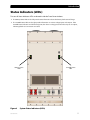
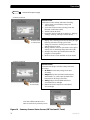
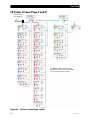
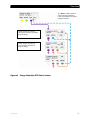
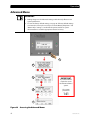
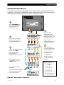
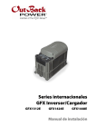
1
Operator’s Manual
OutBack Power Systems
OutBack Power Systems is a leader in advanced energy conversion technology. Our products include
true sine wave inverter/chargers, maximum power point charge controllers, system communication
components, as well as breaker panels, breakers, accessories, and assembled systems.
Contact Information
Telephone:
+1.360.435.6030 (North America)
+1.360.618.4363 (Technical Support)
+34.93.654.9568 (Barcelona, Spain)
+1.360.435.6019 (Fax)
Address:
North America
19009 62nd Avenue NE
Arlington, WA USA
European Office:
C/ Castelló, 17
08830 - Sant Boi de Llobregat
BARCELONA, España
E-mail:
Web Site:
[email protected]
www.outbackpower.com
Disclaimer
UNLESS SPECIFICALLY AGREED TO IN WRITING, OUTBACK POWER SYSTEMS:
(a) MAKES NO WARRANTY AS TO THE ACCURACY, SUFFICIENCY OR SUITABILITY OF ANY TECHNICAL
OR OTHER INFORMATION PROVIDED IN ITS MANUALS OR OTHER DOCUMENTATION.
(b) ASSUMES NO RESPONSIBILITY OR LIABILITY FOR LOSS OR DAMAGE, WHETHER DIRECT, INDIRECT,
CONSEQUENTIAL OR INCIDENTAL, WHICH MIGHT ARISE OUT OF THE USE OF SUCH INFORMATION. THE
USE OF ANY SUCH INFORMATION WILL BE ENTIRELY AT THE USER’S RISK.
Warranty Summary
OutBack Power Systems Inc. warrants that the products it manufactures will be free from defects in
materials and workmanship for a period of five (5) years subject to the conditions set forth in the
warranty detail found inside the back cover of this manual.
OutBack Power Systems cannot be responsible for system failure, damages, or injury resulting from
improper installation of their products.
Notice of Copyright
SmartRE Operator’s Manual ©April 2009 by OutBack Power Systems. All Rights Reserved.
Trademarks
SmartRE™ is a registered trademark of OutBack Power Systems. OutBack Power is a registered
trademark of OutBack Power Systems.
Date and Revision
April 2009
Part Number
900-0036-01-00
Important Safety Instructions
READ AND SAVE THESE INSTRUCTIONS!
This manual contains important safety instructions for the SmartRE System. Read all instructions and
cautionary markings on the SmartRE and on any accessories or additional equipment included in the
installation. Failure to adhere to these instructions could result in severe shock or possible
electrocution. Exercise extreme caution at all times to prevent accidents.
Symbols Used
Symbol
Description
Ground
AC Current
DC Current
∅
Single-Phase
Sine Wave
WARNING: Hazard to Human Life
This type of notation indicates that the hazard could be harmful to human life.
CAUTION: Hazard to Equipment
This type of notation indicates that the hazard may cause damage to
the equipment.
IMPORTANT:
This type of notation indicates that the information provided is important to
the installation, operation and/or maintenance of the equipment. Failure to
follow the recommendations in such a notation could result in voiding the
equipment warranty.
Audience
This manual is intended for anyone required to operate the SmartRE. Operators must be familiar
with all the safety regulations pertaining to operating this kind of equipment as dictated by local
code. Operators must also have a complete understanding of this equipment’s features and
functions. Do not use this product unless it has been installed by a qualified installer in
accordance with the SmartRE Installation Manual.
900-0036-01-00
1
Important Safety Instructions
Definitions
Table 1
Terms and Acronyms
Acronym
ANSI
FCC
IEEE
NEC
NFPA
OSHA
PV
RE
UL
Definition
American National Standards Institute
Federal Communications Commission (North America)
Institute of Electrical and Electronics Engineers
National Electric Code (North America)
National Fire Protection Association
Occupational Safety and Health Association
Photovoltaic
Renewable Energy
Underwriters Laboratory
General Safety
WARNING: Limitations on Use
This equipment is NOT intended for use with life support equipment or other
medical equipment or devices.
CAUTION: Equipment Damage
Only use components or accessories recommended or sold by OutBack Power
Systems or its authorized agents.
SmartRE System Safety
WARNING: Lethal Voltage
This unit contains no user-serviceable parts. Do not remove the cover to the
wiring compartment while the unit is in operation.
WARNING: Fire Hazard
Do not place combustible or flammable materials within 12 feet (3.7 m) of
the equipment.
CAUTION: Equipment Damage
2
Thoroughly inspect the equipment prior to energizing. Verify that no tools
or equipment have been inadvertently left behind.
Ensure clearance requirements are strictly enforced and that all vents are
clear of obstructions that can prevent proper air flow around or through
the unit.
Sensitive electronics inside the equipment can be destroyed by static
electricity. Be sure to discharge any static electricity built up before
touching the equipment and wear appropriate protective gear.
900-0036-01-00
Important Safety Instructions
Battery Safety
WARNING: Electrocution Hazard
Ensure clearance requirements are strictly enforced around batteries.
Ensure the area around the batteries is well ventilated and clean of debris.
Keep plenty of fresh water and soap nearby in case battery acid contacts
skin, clothing, or eyes.
WARNING: Fire or Burn Hazard
Wear complete eye protection and clothing protection when working with
batteries. Avoid touching your eyes while working near batteries.
If battery acid contacts skin or clothing, wash immediately with soap and
water. If acid enters the eye, immediately flood it with running cold water
for at least 20 minutes and get medical attention immediately.
Never smoke or allow a spark or flame near the batteries.
Keep plenty of fresh water and soap nearby in case battery acid contacts
skin, clothing, or eyes.
WARNING: Explosion Hazard
Never charge a frozen battery.
IMPORTANT:
Baking Soda neutralizes lead-acid battery electrolyte.
Vinegar neutralizes NiCad and NiFe battery electrolyte.
Have a supply of either substance readily available if using these types
of batteries.
Regulatory References
National Electric Code (NEC) Article 690, (current edition)
Canadian Electrical Code, Part I (CSA 107.1)
UL 1741-2005 Static Inverter and Charge Controllers for Use in Photovoltaic Power Systems
American National Standards Institute/National Fire Protection Agency (ANSI/NFPA) 70
Recycling Information
IMPORTANT: Recycle Electronics and Batteries
Batteries are considered hazardous waste and must be recycled according to
local jurisdiction. Inverters and other electronics contain metals and plastics
that can (and should) be recycled. The following are some websites and phone
numbers that provide information and “how” and “where” to recycle batteries
and other electronic equipment.
OutBack Power Systems strongly encourages you to learn about recycling and
to dispose of recyclable items accordingly. The Earth, and OutBack Power
Systems, thanks you for that effort.
900-0036-01-00
3
Important Safety Instructions
Earth 911
Web site:
Address:
Phone:
www.Earth911.com
14646 N. Kierland Blvd., Suite 100
Scottsdale, AZ 85254
+1.480.337.3025 (direct)
OurEarth.org
There is a place on the website for contacting OurEarth.org using email. No direct email address
is provided.
Web site:
http://www.ourearth.org/recycling.htm
Environmental Protection Agency, USA
Web site:
Phone:
Email:
www.epa.gov/recyclecity/
+1.415.947.8000
(Monday –Friday 8:00 AM to 12:00 PM and 1:00 PM to 4:00 PM PST)
[email protected]
Keep America Beautiful, USA
Web site:
Address:
Phone:
Fax:
Email:
www.kab.org/
1010 Washington Boulevard
Stamford, CT 06901
+1.203.659.3000 (Main number)
+1.203.659.3001
[email protected]
Natural Resources Canada
Address:
Phone:
TTY:
Web site:
580 Booth, Ottawa, ON K1A 0E8
+1.613.995.0947
+1.613.996.4397
(Phone and TTY: Monday to Friday, 8:30 a.m. to 4:30 p.m. ET)
http://www.nrcan-rncan.gc.ca/mms-smm/busi-indu/rec-rec-eng.htm
Office of Waste Management, Canada
Address:
Phone:
Web site:
4
Office of Waste Management
Conservation and Protection
Environment Canada
Ottawa, Ontaro K1A 0H3
+1. 819.997.2800
http://www.portaec.net/library/recycling/recycling_in_canada.html
900-0036-01-00
Table of Contents
Important Safety Instructions ...................................................................1
Symbols Used ........................................................................................................................................................................1
Audience .................................................................................................................................................................................1
Definitions...............................................................................................................................................................................2
General Safety .......................................................................................................................................................................2
SmartRE System Safety.......................................................................................................................................................2
Battery Safety.........................................................................................................................................................................3
Regulatory References........................................................................................................................................................3
Recycling Information ........................................................................................................................................................3
Earth 911 .................................................................................................................................................................................................. 4
OurEarth.org ........................................................................................................................................................................................... 4
Environmental Protection Agency, USA ...................................................................................................................................... 4
Keep America Beautiful, USA ........................................................................................................................................................... 4
Natural Resources Canada ................................................................................................................................................................ 4
Office of Waste Management, Canada......................................................................................................................................... 4
Introduction...............................................................................................9
Removing the Front Cover............................................................................................................................................. 10
Status Indicators (LEDs)................................................................................................................................................... 11
SmartRE Status Indicators ...............................................................................................................................................................12
Battery State-of-Charge (SOC) LED Indicators.........................................................................................................................12
Basic Operation/Circuit Breakers 101......................................................................................................................... 13
Operation.................................................................................................15
Energize/Startup................................................................................................................................................................ 15
De-energize/Shutdown................................................................................................................................................... 15
MATE2 System Controller and Display ...................................................................................................................... 16
LED Status Indicators.........................................................................................................................................................................16
Soft Key Functions..............................................................................................................................................................................16
Hot Key Functions ..............................................................................................................................................................................17
Menu Map............................................................................................................................................................................ 19
Power UP Screens...............................................................................................................................................................................20
Main Screen...........................................................................................................................................................................................21
Summary Screens ...............................................................................................................................................................................22
FX Status Screens (Page 1) ..............................................................................................................................................................26
FX Status Screen (Page 2 and 3)....................................................................................................................................................30
Charge Controller (CC) Status Screen .........................................................................................................................................34
FLEXnet DC Monitor Status Screen..............................................................................................................................................38
SETUP Screens......................................................................................................................................................................................42
Advanced Menu ..................................................................................................................................................................................44
Configuring System Parameters ...................................................................................................................................................45
Resetting Factory Default Settings ..............................................................................................................................................46
900-0036-01-00
5
Table of Contents
Maintenance and Troubleshooting .........................................................49
Maintenance ....................................................................................................................................................................... 49
Cleaning the Air Filter .......................................................................................................................................................................49
Basic Troubleshooting..................................................................................................................................................... 50
Communication Errors......................................................................................................................................................................51
Other Resources................................................................................................................................................................. 52
Application or Accessory information ........................................................................................................................................52
How to Contact Technical Support..............................................................................................................................................52
Recycling Information.......................................................................................................................................................................52
How to Arrange for Warranty Service ........................................................................................................................ 53
Return Material Authorization (RMA)..........................................................................................................................................53
Returning Product to OutBack ......................................................................................................................................................54
Specifications...........................................................................................55
Electrical Specifications................................................................................................................................................... 55
Mechanical Specifications.............................................................................................................................................. 56
Environmental Specifications ....................................................................................................................................... 56
Index ........................................................................................................57
SmartRE Warranty Registration Card ......................................................59
*Extended Warranty......................................................................................................................................................... 60
Warranty ..................................................................................................61
6
900-0036-01-00
Table of Contents
List of Tables
Table 1
Table 2
Terms and Acronyms.............................................................................................................................................................2
Basic Troubleshooting ....................................................................................................................................................... 50
List of Figures
Figure 1
Figure 2
Figure 3
Figure 4
Figure 5
Figure 6
Figure 7
Figure 8
Figure 9
Figure 10
Figure 11
Figure 12
Figure 13
Figure 14
Figure 15
Figure 16
Figure 17
Figure 18
Figure 19
Figure 20
Figure 21
Figure 22
Figure 23
Figure 24
Figure 25
Figure 26
Figure 27
Figure 28
Figure 29
Figure 30
Figure 31
Figure 32
Figure 33
Figure 34
Figure 35
Figure 36
Figure 37
Figure 38
900-0036-01-00
Typical Grid-Interactive Application................................................................................................................................9
Removing the Front Cover ............................................................................................................................................... 10
System Status Indicators (LEDs) ..................................................................................................................................... 11
SmartRE Status Indicators (LEDs)................................................................................................................................... 12
Battery Status Indicators (LEDs) ..................................................................................................................................... 12
SmartRE Breakers and Mechanical Interlocks ........................................................................................................... 13
DC Breakers Enlargement................................................................................................................................................. 14
AC Breakers and Mechanical Interlocks Enlargement ........................................................................................... 14
Startup Procedures.............................................................................................................................................................. 15
Shutdown Procedures ....................................................................................................................................................... 15
MATE2 Display and Control Features........................................................................................................................... 16
Inverter Control Screen...................................................................................................................................................... 17
AC Input Control Screens (1-3) ....................................................................................................................................... 18
AC Input Control Screens................................................................................................................................................. 19
MATE2 Startup Screens ..................................................................................................................................................... 20
Main Screen............................................................................................................................................................................ 21
Summary Screens (State-of-Charge and DC Now)................................................................................................. 22
Summary Screens Status Screens (DC Today and DC Bat)................................................................................... 23
Summary Screens Status Screens (FX Total and CC Total)................................................................................... 24
Status Screens ....................................................................................................................................................................... 25
FX Status Screen (Page 1 Summary)............................................................................................................................. 26
FX MODES Status Screens................................................................................................................................................. 27
FX METER Status Screens .................................................................................................................................................. 28
FX BATT Status Screens ..................................................................................................................................................... 29
FX Status Screen (Page 2 and 3)..................................................................................................................................... 30
FX ERROR Status Screens .................................................................................................................................................. 31
FX WARN Status Screens ................................................................................................................................................... 32
FX DISCON and SELL Status Screens (Page 3)........................................................................................................... 33
Charge Controller Status Screens (Page 1) ................................................................................................................ 34
Charge Controller MODE Status Screens.................................................................................................................... 35
Charge Controller METER Status Screens ................................................................................................................... 36
Charge Controller SETP Status Screens....................................................................................................................... 37
FLEXnet DC Status Screens .............................................................................................................................................. 38
FLEXnet DC METER Status Screens ............................................................................................................................... 39
FLEXnet DC SHUNT Status Screens............................................................................................................................... 40
FLEXnet DC BATT Status Screens................................................................................................................................... 41
MATE Setup Screen (Page 1)............................................................................................................................................ 42
MATE Setup Screen (Page 2 and 3) ............................................................................................................................... 43
7
Table of Contents
Figure 39
Figure 40
Figure 41
Figure 42
Figure 43
Figure 44
8
Accessing the Advanced Menus .................................................................................................................................... 44
Configuring System Parameters .................................................................................................................................... 45
Resetting Factory Default Settings (page 1).............................................................................................................. 46
Resetting Factory Default Settings (page 2).............................................................................................................. 47
Cleaning the Air Filter......................................................................................................................................................... 49
How to Clear a Comm Error ............................................................................................................................................. 51
900-0036-01-00
Introduction
Thank you for using a SmartRE™ from OutBack Power Systems. The SmartRE System is an integrated
Balance-of-Systems solution designed to be quick to install and easy to use.
The SmartRE System is intended for grid-interactive applications up to 6 kW in North America. It is
intended for use with photovoltaic (PV) modules for harvesting energy and a battery bank for energy
storage. SmartRE is certified as “Grid-interactive” meaning that excess energy (energy that exceeds
usage) will be returned to the Grid (Sell Mode).
The SmartRE System is designed with the following features:
2500 W, 3000 W , 5000 W, and 6000 W units
120 Vac-60 Hz and 120/240 Vac-60 Hz configurations
Rated for Indoor and Outdoor Installations
Includes chassis mounting brackets and interconnecting mounting brackets for wall-mounting
Uses MPPT technology to maximize the harvest from solar modules
ETL listed to UL 1741
Figure 1
900-0036-01-00
Typical Grid-Interactive Application
9
Introduction
Removing the Front Cover
Just inside the Front Cover
there are two brackets that
interlock with two brackets on
the interior cover to hold the
front cover in place.
1
If a lock has been installed,
use the key provided with
that lock to unlock the
Front Cover.
2
Lift the Front Cover upward to
dislodge it from the brackets.
3
Then swing the
bottom of the Front
Cover away from
the enclosure and
lower it to remove it
from under the
Top Cap.
Reverse these directions to
re-install the Front Cover.
Figure 2
10
Removing the Front Cover
900-0036-01-00
Introduction
Status Indicators (LEDs)
Two sets of Status Indicators LEDs are located inside the Front Cover windows.
The Battery Status LEDs on the left provide status information about the battery bank state-of-charge.
The SmartRE Status LEDs on the right provide information on various voltage inputs and outputs. If the
SmartRE Status Indicators are illuminated green, then there is voltage present for those inputs or outputs,
indicating that those connections are active.
Battery Status
LEDs
Figure 3
900-0036-01-00
SmartRE Status
LEDs
System Status Indicators (LEDs)
11
Introduction
SmartRE Status Indicators
There are five LEDs for SmartRE component status information. If voltage is detected, the LEDs illuminate.
Voltage can be detected regardless of breaker position. The LEDs are assigned to specific inputs/outputs
as follows.
SmartRE Status
LEDs
Figure 4
Solar (Green)..........................Illuminates if PV voltage is detected.
Inverter Out (Green) ..........Illuminates if the Inverter is producing power.
Does NOT illuminate if Bypass mode is being used.
AC Out (Green) .....................Illuminates if voltage is detected on any of the AC outputs.
Grid IN (Green)......................Illuminates if voltage is detected on the AC1 IN Input.
Gen IN (Yellow).....................Illuminates if voltage is detected on the AC2 IN Input.
SmartRE Status Indicators (LEDs)
Battery State-of-Charge (SOC) LED Indicators
Five LEDs provide a visual indication of the state-of-charge (SOC) of the battery bank. LEDs will illuminate solid
or blink depending on the condition of the battery bank.
Battery SOC
LEDs
SOC
Figure 5
12
Green
Yellow
Yellow
Yellow
Red
>90%
Blinking Green LED: .......... Charge parameters are met.
Solid Green LED: ................. SOC is above 90%
Off Red LED:.SOC is above 59%
Solid Red LED: ..................... SOC is greater than 49% but less than 60%
Blinking Red LED: ................ SOC is less than 50%
80-89%
70-79%
60-69%
Solid = 50-59%
Blinking = <50%
Battery Status Indicators (LEDs)
900-0036-01-00
Introduction
Basic Operation/Circuit Breakers 101
IMPORTANT:
ENERGIZING/Power ON: Closing the circuit breaker, completes the
electrical circuit, which enables power to flow. This turns the power ON.
DE-ENERGIZING/Power OFF: Opening the circuit breaker, disrupts the
circuit, which stops the flow of power. This turns the power OFF.
AC Breakers
DC Breakers
Mechanical
Interlocks
CLOSED
(I)
ON
Figure 6
900-0036-01-00
OPEN
(O)
OFF
AC IN 1 Closed (I) ON
AC IN 2 Open (O) OFF
AC IN 2 Closed (I) ON
AC IN 1 Open (O) OFF
SmartRE Breakers and Mechanical Interlocks
13
Introduction
Ground Fault
Protection
Use for dedicated
DC loads
PV Input
Battery Positive
(Inverter) Input
Breakers shown in OFF position.
Figure 7
DC Breakers Enlargement
Grid Input
Generator Input
AC to a Subpanel.
Use for dedicated
AC loads.
Sends AC from the Grid or generator to the
loads and bypasses the inverter(s)
20A Dual-pole Breaker for 240 Vac Loads.
(Not available in all models)
Breakers shown in OFF position.
Figure 8
14
AC Breakers and Mechanical Interlocks Enlargement
900-0036-01-00
Operation
Energize/Startup
1.
2.
3.
4.
Close the DC Breakers from the battery bank to the inverter.
Close the AC Output Breakers.
Close the AC Input Breakers.
Close the PV input Breakers.
3
Figure 9
2
4
1
1
3
Startup Procedures
De-energize/Shutdown
1. Open the PV Breakers.
2. Open the AC Breakers.
3. Open the DC Breaker for the Battery.
2a
2b
Figure 10 Shutdown Procedures
900-0036-01-00
15
Operation
MATE2 System Controller and Display
A MATE2 System Controller and Display is included for system configuration and monitoring activities.
It consists of a 4-line LCD and two Status LEDs for system display. The MATE2 also has four soft keys
and two Hot Keys for software menu navigation. Each soft key corresponds to the word on the screen
directly above it except when viewing the Summary screens.
LED Status Indicators
AC Input Status LED (yellow)
ON (Solid) – AC is connected and in use.
ON (Flashing) – AC is available, but not connected.
OFF (not illuminated) – No AC is present.
Inverter Status LED (green)
ON (Solid) — inverter is powering loads or selling to the grid.
ON (Flashing)—the inverter is in search or power save modes.
Off (not illuminated) — either 1) the inverter is not converting DC power to AC power, or 2) when the AC
input source is powering the loads.
AC Input Status LED
(yellow)
4-line LCD
Display
Inverter Status
LED (green)
“Hot Key”
INV
Button
“Hot Key”
AC IN
Button
“Soft” Keys (x4)
Figure 11 MATE2 Display and Control Features
Soft Key Functions
There are four Soft Keys available to navigate through the Menu Map. Each Soft Key corresponds to
the word on the screen directly above it except when viewing the Summary Screens.
16
Soft Key navigation (<UP>, <DOWN>, <BACK>, or <TOP>).
Soft Key Settings (<OFF>, <AUTO>, <ON>, <INC> to increase values and <DEC> to decrease values).
Other: The soft keys perform other functions depending on the individual menu screen. These “Other”
functions may be not applicable to this product and therefore may not be shown in this manual.
900-0036-01-00
Operation
Hot Key Functions
There are two “hot” keys available to bring up the most commonly used control screens.
INV Hot Key: Pushing the INV hot key will display the Inverter Control screen to control the FX
inverting function.
AC IN Hot Key: Pushing the AC IN hot key displays the first of four AC Input Control screens. Pushing
AC IN repeatedly cycles through the four AC Input Control screens.
Set points:
<OFF> - turns off all FX inverters
connected to the MATE.
<SRCH> - begins search mode if the AC
load connected is smaller than allowed by
the programming of the search function.
<ON> - turns on all FX inverters
connected to the MATE.
<OK> - Returns the Display to the
Main Screen.
Figure 12 Inverter Control Screen
900-0036-01-00
17
Operation
Continued on
page 19
Continuing to
press AC IN cycles
through the four
AC Input Control
screens.
Set points:
<USE> - enables the FX to connect to an AC input
source.
<DROP> - disconnects the AC input source but will
allow it to be reconnected if the “low battery cut-off”
set point occurs if the FX is overloaded.
<OK> - returns to the point in the menu system before
entering the AC INPUT CONTROL Menu Cycle.
Set points:
The Gen Start Control Screen
will be available for viewing,
but this function is not
recommended for use with
this product.
<MAN OFF> - indicates the user manually turned off the
AGS mode.
<AUTO OFF or AUTO ON> - allows the MATE to
automatically start and stop the generator according the
settings in the Advanced AGS Menu.
<MAN ON> - manually overrides the AGS mode turning
the generator on.
<OK> - Returns to the point in the Menu System where
the user entered the GEN START Control Screen.
Set points:
<OFF> - disables the charger function.
<AUTO> - enables automatic battery charging, silent,
and “re-float” when an AC input source is connected.
<ON> - Recharges the batteries, but eventually remains
in the “float” charging stage (and eliminates silent mode)
until the AC input is disconnected.
<OK> - returns to the point in the menu system where
you entered the CHARGER CONTROL screen.
Figure 13 AC Input Control Screens (1-3)
18
900-0036-01-00
Operation
Continued from
page 18
See Caution below.
Soft Key Options:
<BULK> - starts a BULK charge.
<EQ> - starts an EQUALIZE charge.
<OK> - Returns to the point in the Menu
System where the user entered the GEN
MODE CONTROL Screen.
Figure 14 AC Input Control Screens
CAUTION: Battery Damage
This product recommends the use of AGM (or sealed) batteries. Sealed Batteries
should NEVER be equalized.
Menu Map
IMPORTANT:
The SmartRE is composed of four individual OutBack components that will have
their own set of software screens. Some screens, although available for the
individual components, may not be applicable for use with this product. Those
screens that are not applicable for use with this product are not illustrated in this
manual. Please consult your local installer if you have any questions about the
additional screens or you can get the manuals with complete programming
instructions at www.outbackpower.com.
900-0036-01-00
19
Operation
Power UP Screens
IMPORTANT:
You will need the code and serial number
of the MATE2 if contacting OutBack Power
Systems regarding its operation.
“Code” dictates the MATE2’s operation
and features.
“Serial #” matches the bar code sticker
inside the MATE on its circuit board.
“Screen EE” refers to the MATE2’s
Menu System.
Main Screen
Figure 15 MATE2 Startup Screens
20
900-0036-01-00
Operation
Main Screen
The MAIN screen appears after the MATE detects the HUB (and any devices connected to it).
The SUMMARY Soft Key leads to
menus that show the direction and
amount of power flow in regard to
inverting, charging, selling, and/or
pass through. It also shows the
voltage of the battery.
The STATUS Soft Key leads to menus that
reflect system status such as modes, meters,
battery condition, errors and warnings.
The ADVANCED Soft Key leads
to menus that allow for
changing each component’s
advanced settings. For this
system, that would include the
Battery Amp-hour setting and
the Return Amps setting.
The SETUP Soft Key leads to menus that
change basic user-preference settings
(e.g., screen contrast).
To return to the Main Screen from
any other screen, press the two left
Soft Keys at the same time.
Figure 16 Main Screen
900-0036-01-00
21
Operation
Summary Screens
Main Screen
From the Main Screen, press the <SUM>
Soft Key to access the Summary Screens.
Summary Screen #1
State-of-Charge Screen:
Displays the current state-of-charge of the batteries
in both a bar graph and a percentage.
The text under the bar graph describes whether the
net activity on the battery is presently resulting in a
charge or a discharge.
Press to scroll
to next screen.
Summary Screen #2
DC Now Screen:
Summarizes net DC activity (charging, discharging,
battery condition) at this moment.
Press to scroll
to next screen.
SOC: current battery state-of-charge.
IN: amperes and kilowatts from all
charging sources.
OUT: amperes and kilowatt consumed by loads.
BAT: the difference between IN and OUT screens
for amperes and kilowatts; i.e., shows the net
result on the batteries. A positive value
indicates charging. A negative value indicates
discharging.
Continued on next page
Figure 17 Summary Screens (State-of-Charge and DC Now)
22
900-0036-01-00
Operation
Continued from previous page
Summary Screen #3
DC Today screen:
Summarizes DC activity (charging, discharging, battery
condition) since last midnight.
minSOC: lowest battery state of charge since midnight.
IN: amp-hours and kilowatt-hours accumulated
from all charging sources.
OUT: amp-hours and kilowatt-hours consumed by
the loads or sold back to the grid.
Press to scroll
to next screen.
BAT: the difference between IN and OUT screens
for amp-hours and kilowatt-hours; i.e., shows
the net result on the batteries. A positive value
indicates storage (fully charged). A negative
value indicates loss (not fully charged).
Summary Screen #4
DC BAT screen:
Summarizes the battery condition. The top line shows
voltage and state-of-charge at the time of reading.
Bat: net amperes and kilowatts from all charge
sources and loads at this moment. Positive
value means the net flow is battery charge;
negative means the net flow is battery drain.
Net: accumulated amp-hours and kilowatthours since the last time the batteries
reached their fully-charged parameters.
Press to scroll
to next screen.
Days Since Full: The number of days since the batteries
last reached their full-charge parameters.
These parameters are described in the
FLEXnet DC User’s Manual.
Continued on next page
Figure 18 Summary Screens Status Screens (DC Today and DC Bat)
900-0036-01-00
23
Operation
Continued from previous page
Summary Screen #5
FX Total screen:
Summarizes inverter activity at the time of reading.
Top line shows present battery voltage and
state-of-charge.
Second line shows inverter operating mode and
kilowatts used for that activity.
Third line shows AC loads.
Fourth line shows inverter AC operation (i.e., “Buying”,
“Selling”, “Zeroing”, “AC Drop” and “No AC IN”).
Press to scroll
to next screen.
Buying: Unit is drawing power from the utility through
its AC Input for either charging or for loads.
Selling: The inverter is returning excess DC (PV) to the
grid through its AC input.
Zeroing: Unit has excess DC power but not enough to
actively sell. It is delivering that power to the loads.
AC Drop: AC power is present but the inverter has
judged it as unacceptable.
No AC In: There is no AC available on any AC inputs.
Summary Screen #6
CC Total Screen:
Summarizes PV charge controller activity at the time
of reading.
Press to scroll
to next screen.
CC Totals shows battery voltage at the time
of reading.
Output displays the total delivered PV amperes
and kilowatts (i.e., total output available to the
batteries from all charge controllers.).
Today displays the total PV kilowatt-hours
accumulated since midnight.
Bottom line shows amp-hours accumulated
since midnight.
Press this Soft Key to Return to the
Main Screen from any Summary Screen.
Figure 19 Summary Screens Status Screens (FX Total and CC Total)
24
900-0036-01-00
Operation
Choosing a Device
Figure 20 Status Screens
900-0036-01-00
25
Operation
FX Status Screens (Page 1)
See Figure 22 on page 27 for details on
FX MODE Screens.
See Figure 23 on page 28 for details on
FX METERS Screens.
See Figure 24 on page 29 for details on
FX BATT Screens.
FX Status Screen PG
2 and PG 3 are
shown on page 30
Figure 21 FX Status Screen (Page 1 Summary)
26
900-0036-01-00
Operation
The <Port> Soft Key switches
status monitoring between
ports on the HUB (i.e., between
multiple inverters).
<Change Mode>
Commands inverter on,
off or in Search.
Duplicates Hot Key.
INVERTER CONTROL
P01
CURRENTLY:
ON
Select
Returns to
Mode Screen.
<Change Mode>
Commands AC input to
use or drop an AC
source.
AC INPUT CONTROL
P01
CURRENTLY:
USE
Duplicates Hot Key.
Select
Returns to
Mode Screen.
<Change Mode>
Commands charge
controller to be OFF, ON
or AUTOmatic.
CHARGER CONTROL
P01
CURRENTLY:
AUTO
Select
Returns to
Mode Screen.
Not used in the SmartRE.
<Change Mode>
Commands charger to
turn equalization mode
ON or OFF.
EQUALIZE CONTROL
P01
eq enabled: NO
Duplicates Hot Key.
Select
Returns to
Mode Screen.
Figure 22 FX MODES Status Screens
900-0036-01-00
27
Operation
The <Port> Soft Key switches
status monitoring between
ports on the HUB (i.e., between
multiple inverters).
CURRENT
ACTIVITY:
off
search
on
charge
silent
float
eq
chrg off
support
sell
passthru
TARGET
ACTIVITY:
Sell
RE
Float
Bulk
EQ
inv: Kilowatts taken
from the batteries while
inverting.
chg: Kilowatts put into
the batteries while
charging.
zer: Kilowatts of PV
delivered to loads
when there is not
enough to actively sell.
buy: Total kilowatts
drawn from AC source
(charge and loads)
OFF..............Unit turned off; no AC source
Search .......Unit on but sleeping;
no load demand
ON ...............inverting from batteries;
no AC source
CHARGE ...Charging batteries from
AC source
Silent..........Using AC source, charging
complete
Float ...........Maintaining batteries
once full
EQ ...............running controlled battery
overcharge
Chr Off.......Using AC source;
charger turned off
Output voltage:
Shows the AC voltage available at
the FX’s AC output.
Input voltage:
Shows the AC voltage available
at the FX’s AC input, from utility
or generator.
Inverter current:
Shows the AC amperage drawn
by loads on AC output when
inverter is ON and no AC source
is connected.
Charger current:
Shows the AC amperage used by
the FX’s charger.
Input current:
Shows the AC amperage drawn
by the FX’s AC input
(combination of charging and
loads).
Sell current:
Shows the AC amperage sold
back to the utility.
FX firmware:
Shows the Current FX software
version.
Figure 23 FX METER Status Screens
28
900-0036-01-00
Operation
The <Port> Soft Key switches status
monitoring between ports on the HUB
(i.e., between multiple inverters).
Battery Actual: Shows true battery voltage.
Battery Temp Compensated: Shows
equivalent battery voltage, adjusted for
effects of temperature.
Absorb set point: Shows charger set point
for “Absorption voltage”, first (Bulk) stage
of charge.
Absorb time remaining: Shows charger
running time for second (Absorb) stage
of charge.
Float set point: Shows charger set point, for
“Float voltage”, third (Float) stage of charge.
Float time remaining: Shows charger Float
timer, for duration of third stage.
Refloat set point: Shows charger set point
for resumption of third stage (for battery
maintenance).
Equalize set point: Shows charger set point
for battery equalization. (Do NOT equalize
sealed batteries.)
Equalize time remaining: Shows charger
running time for the remainder of the
Equalization cycle.
Batt Temp: Shows battery temperature.
This is in digital counts, not degrees, and is
only usable for troubleshooting.
Figure 24 FX BATT Status Screens
900-0036-01-00
29
Operation
FX Status Screen (Page 2 and 3)
From FX Status
Screen Page 26
The <Port> Soft Key switches status
monitoring between ports on the HUB
(i.e., between multiple inverters).
Figure 25 FX Status Screen (Page 2 and 3)
30
900-0036-01-00
Operation
The faults described
on this page are
considered “hard
faults”. The inverter
must be turned OFF
and then ON to reset.
ERROR screens can
only display errors;
they do not offer any
means to correct
them.
Generally the nature
of the error suggests
how to correct it.
All screens read status as “No”
under normal conditions. If the
unit shuts off due to a specified
error condition, that screen will
change to “Yes”.
Low AC Output Voltage: Load too
high. Inverter could not supply
enough AC voltage to meet demand
Stacking Error Detected:
Communication problem among
stacked units
Inverter Overtemp: Unit has reached
its maximum allowed operating
temperature
Low Battery Voltage: Battery voltage
is below the LOW BATTERY CUT-OUT
VOLTAGE set point. (This error can be
triggered by other events. It can
trigger with low AC output or AC
shorted.)
The <Port> Soft Key
switches status
monitoring between
ports on the HUB
(i.e., between multiple
inverters).
Phase loss error: Not active in
this model
High Battery Voltage: Battery voltage
rose above the safe high battery
voltage level for 10 seconds
AC Output Shorted: Full short on
output; inverter reached its maximum
current and shut down
AC Output Backfeed: Usually
indicates another AC power source was
connected to the unit’s AC output
Figure 26 FX ERROR Status Screens
900-0036-01-00
31
Operation
All warning screens read status as “No”
under normal conditions. If the
appropriate condition is met, that
screen will change to “Yes.”
ACIN freq too high: AC source is above 60.5 Hz
(upper limit) and will be dropped.
ACIN freq too low: AC source is under 59.3 Hz
(lower limit) and will be dropped.
ACIN voltage too high: AC source’s voltage is
over 132 Vac (default limit) and will be dropped.
ACIN voltage too low: AC source’s voltage
is under 108 Vac (default limit) and will
be dropped.
ACIN input current exceeds max:
AC loads are drawing more current than the
rating of the FX allows.
Temperature sensor fault: An internal FX
temperature sensor is malfunctioning.
Internal comm error detected: There is a
communication problem between the MATE
and the FX.
Internal fan failure detected: The FX’s internal
cooling fan is not operating properly.
The following items are not warnings, but are data
readings related to the temp sensor warning. (These
values are used for troubleshooting purposes. The
higher the numerical value, the cooler the
temperature.)
Airtemp: Displays a numeric value representing
the air temperature around the FX.
The <Port> Soft Key
switches status monitoring
between ports on the HUB
(i.e., between multiple
inverters).
Fettemp: Displays a numeric value representing
the temperature of the FETs (Field Effect
Transistors).
Captemp: Displays a numeric value
representing the temperature of the ripple
capacitors.
Figure 27 FX WARN Status Screens
32
900-0036-01-00
Operation
From FX Status
Screen Page 20
ACIN Freq too high:
displays “yes” if the AC
source exceeds 69 Hz
and the FX disconnects
from the source.
ACIN Freq too low:
displays “yes” if the AC
source exceeds 59.3 Hz
and the FX disconnects
from the source.
AC IN voltage > Max:
displays “yes” if the AC
source exceeds 132 Vac
and the FX disconnects
from the source.
AC IN voltage < Min:
displays “yes” if the AC
source exceeds 108 Vac
and the FX disconnects
from the source.
Stop Sell Reason: Displays a
numerical value (11 in sample screen
shown here) indicating a reason the FX
has stopped selling power to the utility
grid. This screen is used for
troubleshooting by OutBack Power
System Technicians.
Stop Sell Reasons
0 No fault
1 Input frequency/voltage out of
tolerance resulting in 5-minute
no-sell timer.
2 Island detecting resulting in
5-minute no-sell timer.
7 Silent Mode, output relay still
engaged, no RE to sell.
8 Silent Mode, output relay
disengaged, no RE to sell.
The <Port> Soft Key switches status
monitoring between ports on the HUB
(i.e., between multiple inverters).
Figure 28 FX DISCON and SELL Status Screens (Page 3)
900-0036-01-00
33
Operation
Charge Controller (CC) Status Screen
See Figure 30 on page 35 for
details on CC MODE Screens.
The <Port> Soft Key
switches status monitoring
between ports on the HUB
(i.e., between multiple
inverters).
See Figure 31 on page 36 for
details on CC METER Screens.
See Figure 32 on page 37 for
details on CC SETPT Screens.
Figure 29 Charge Controller Status Screens (Page 1)
34
900-0036-01-00
Operation
Charger Mode:
Shows one of five charger states (Bulk,
Absorption, Float, Silent, Equalization)
Aux Relay Mode:
Shows the operating mode of 12 Vdc
Aux Relay.
Aux Relay State:
Shows whether the Aux relay is off or on.
The <Port> Soft Key switches
status monitoring between
ports on the HUB (i.e., between
multiple inverters).
Figure 30 Charge Controller MODE Status Screens
900-0036-01-00
35
Operation
The <Port> Soft Key switches
status monitoring between
ports on the HUB (i.e., between
multiple inverters).
Initial screen, beginning with
bulk/absorb/float or one of five
charger states.
In: DC volts and amperes presently
harvested from PV array.
Out: DC volts and amperes
presently charging the battery.
Charger watts:
Shows the wattage presently
charging the battery.
Charger kWhrs:
Shows the kilowatt-hours
produced on output today.
Charger amps dc:
Shows the DC amperes
presently charging the
battery.
Battery voltage :
uncompensated present
battery voltage.
Panel voltage:
Shows the present PV array
voltage.
CC firmware revision:
Shows the current version of
charge controller software.
Figure 31 Charge Controller METER Status Screens
36
900-0036-01-00
Operation
The <Port> Soft Key switches
status monitoring between
ports on the HUB (i.e., between
multiple inverters).
Shows charger set point for
“Absorption voltage”, first (Bulk)
stage of charge.
Shows charger set point, for
“Float voltage”, third (Float)
stage of charge.
Figure 32 Charge Controller SETP Status Screens
900-0036-01-00
37
Operation
FLEXnet DC Monitor Status Screen
Figure 33 FLEXnet DC Status Screens
38
900-0036-01-00
Operation
Shows the Amps/kilowatts flowing thru Shunts A, B or C at
the moment of reading. Positive value means amp flow
into the batteries; negative means a load on the batteries.
Shows the Net amp-hours/kilowatt-hours accumulated
since the charge parameters were last met. Positive value
means that shunt shows a net charge to the battery;
negative means a net discharge.
Removed: Shows the Amp-hours/kilowatt-hours
removed from the batteries by the FX inverter (s). This
number is cumulative since the charge parameters were
last met.
Charged: Shows the Amp-hours/kilowatt-hours used to
charge the batteries by the FX. This number is cumulative
since the charge parameters were last met.
Removed: Shows the Amp-hours/kilowatt-hours
removed from the batteries by the Charge Controller(s).
This number is cumulative since the charge parameters
were last met.
Charged: Shows the Amp-hours/kilowatt-hours used to
charge the batteries by the Charge Controller(s). This
number is cumulative since the charge parameters were
last met.
DC Firmware Revision: Shows the firmware
revision number.
Figure 34 FLEXnet DC METER Status Screens
900-0036-01-00
39
Operation
Max Removed Amps: Shows the
maximum amps removed from the
batteries by the FX inverter (s).
<RESET> will reset the value to
zero in all screens.
Max Removed kWatts: Shows the
maximum kilowatts removed from the
batteries by the FX inverter (s).
Max Charged Amps: Shows the
maximum amps used to charge the
batteries by the FX Inverter(s).
Max Charged kWatts: Shows the
maximum kilowatts used to charge the
batteries by the FX Inverter(s).
Max Removed Amps: Shows the
maximum amps removed from the
batteries by the Charge Controller(s).
Max Removed kWatts: Shows the
maximum kilowatts removed from the
batteries by the Charge Controller(s).
Max Charged Amps: Shows the
maximum amps used to charge the
batteries by the Charge Controller(s).
Max Charged kWatts: Shows the
maximum kilowatts used to charge the
batteries by the Charge Controller(s).
Figure 35 FLEXnet DC SHUNT Status Screens
40
900-0036-01-00
Operation
Total days at 100%: Displays the number of days
the battery has been at 100% State-of-charge.
Days since charge parameters met: Displays the
number of days since the battery last met its charge
parameters.
Battery min today: Displays the minimum battery
voltage since it was last reset by the user or since
midnight passed.
Battery max today: Displays the maximum battery
voltage since it was last reset by the user or since
midnight passed.
Temp com’d batt Set point: Displays the fullycharged voltage compensated for temperature.
System Battery Temperature: If the remote
temperature sensor senses temperature is between
10°C and 60°C on the batteries, it will display the
value in degrees Celsius. If the sensor is damaged or
fails, or if the temperature is outside of the range
listed above, ### will appear.
Cycle charge factor: Displays the amp-hours
removed and amp-hours returned (as a percentage)
during the last battery cycle.
Cycle kWhr Charge efficiency: Displays the
kilowatt-hours removed and returned (as a
percentage) during the last battery cycle.
Lifetime kilo AH (1000 amp-hours) removed:
Displays the total amp-hours removed from the
battery over the life of the battery. This is essentially
an odometer of battery usage.
Figure 36 FLEXnet DC BATT Status Screens
900-0036-01-00
41
Operation
SETUP Screens
IMPORTANT:
Basic setup for the MATE should have been done by the installer. The following
screens are provided in the event that changes need to be made in display
preferences (e.g., screen contrast) or if communication errors occur between the
components and needs to be reset.
MATE Setup
Screen PG 2
and PG 3 are
shown on
page 43
Figure 37 MATE Setup Screen (Page 1)
42
900-0036-01-00
Operation
Continued from
page 42
MATE Setup
Screen
PAGE 3
MATE Setup Screen PAGE
2
See page 51 for
resetting
Comm Error
tally.
Figure 38 MATE Setup Screen (Page 2 and 3)
900-0036-01-00
43
Operation
Advanced Menu
IMPORTANT:
Making changes to the Advanced Settings could adversely affect current
system performance.
To reset the factory-default settings, see page 46. If factory default settings
are restored, it also may be necessary to reset the “Battery Amp Hours” and
“Return Amps” settings. Consult with the system installer or system
documentation to reset the appropriate values if necessary.
1
2
3
IMPORTANT:
A password will be
required to access
the Advanced Menu
system.
4
The system
password is
141
5
Figure 39 Accessing the Advanced Menus
44
900-0036-01-00
Operation
Configuring System Parameters
IMPORTANT:
These settings should be pre-determined by the system installer.
IMPORTANT:
Access the Advanced Menu as
instructed on page 44.
To change Battery Amp-hours:
1.
2.
3.
4.
Press the <BAT> Soft Key.
Press the <INC> or <DEC> Soft
Key to change the parameter.
Press <ADV> to return to PG 1.
Press <PG2> to advance to the
next setup page.
To change Return Amps:
1.
2.
3.
4.
5.
Press the <CHARGE> Soft Key.
Press the <INC> or <DEC> Soft
Key to change the parameter.
Press <TOP> to return to PG 2.
Press <PG3> to advance to the
next setup page.
Press <Main> to return to the
Main Screen.
Figure 40 Configuring System Parameters
900-0036-01-00
45
Operation
Resetting Factory Default Settings
Continued on the
next page…
Follow this menu
map to reset the FX
Inverter.
Follow this menu
map to reset the
FLEXmax 80 Charge
Controller.
Figure 41 Resetting Factory Default Settings (page 1)
46
900-0036-01-00
Operation
Continued from the
previous page…
Follow this menu map to
reset the FLEXnet DC.
Follow this menu map
to reset the MATE2.
Figure 42 Resetting Factory Default Settings (page 2)
900-0036-01-00
47
Operation
Notes:
48
900-0036-01-00
Maintenance and Troubleshooting
IMPORTANT:
Be sure to review the important safety information at the front of this manual
before proceeding with any maintenance or troubleshooting.
Service should only be provided by qualified personnel.
See Figure 2 for instructions to remove the Front Cover.
Maintenance
Cleaning the Air Filter
1 Follow the instructions on page 10 for
Removing the Front Cover.
2 Gently remove the filter from the front of
the grill above the breakers.
3a For “dusty” conditions, Clean the filter
with compressed air.
3b For “dirty” conditions, clean with water
and a mild detergent. Be sure the filter is
completely dry before returning it to the
front grill.
4 Gently tuck the filter back into the groove
around the edge of the grill.
Figure 43 Cleaning the Air Filter
900-0036-01-00
49
Troubleshooting
Basic Troubleshooting
Table 2
Basic Troubleshooting
Symptom
COMM ERROR is
displayed on the
MATE2
Possible Cause
Remedy
DC Breaker for the specific
component is in the OFF position.
Check the Breaker for the device in question.
CAT5 Cable may be damaged.
Replace the CAT5 cable.
Inverter is displaying
Shorted output or
Backfeed error.
Shorted Wiring, or damaged
component.
Isolate the inverters input and output, recycle
the on off switch if the inverter powers up and
runs 120V then problem is wiring or loads If
not contact Tech Support.
High or Low Battery
Voltage
Control Board or FET Board Error.
Contact Tech Support to authorize a
replacement.
Not Charging
Control Board may not be sensing
the battery voltage properly. Or FET
board may be failing.
Contact Tech Support to authorize a
replacement.
No Pass Thru
Relay may have failed or AC Board
may have failed.
If you hear the relay transfer (audible click) then
the problem should only be the AC board. If
there is no transfer, then your problem is the
control board. Contact Tech Support to
authorize a replacement.
AC Input LED is
blinking, but Error LED
is blinking
continuously.
Bad input voltage.
Control may be not sensing the
input voltage properly.
Replace the Control Board. Contact Tech
Support to authorize a replacement.
Temp Sensor fails or
faults
Temp Sensor has may have failed.
Replace the sensor and/or the FET board.
The screen reading 255 or zero in the
WARN Menu will tell you which
Reconnect the sensor if possible.
sensor it is.
MATE is displaying a
Technician didn’t connect the
“temp count of 255 or
transformer temp sensor when
0” measured in one of
servicing units.
the airtemp, fettemp
and captemp screens in
the WARN Menu.
Contact Tech Support to authorize a
replacement. Tell them which screen reads 255
or zero.
Inverter Shuts Down.
Internal Fan Failure
50
Inverter internal fan may have failed.
Or inverter has overheated (even if
fan is still running, the inverter may
not realize the fan is still running.)
Check the temp sensor menu under the Warn
Screen to verify that this is not the case.
If the inverter temp counts are low enough
(>75 counts), turn off the system and allow the
inverter to cool off.
900-0036-01-00
Troubleshooting
Communication Errors
If the MATE receives too many interrupted or corrupt communications with the other networked
components, it will display a ‘COMM ERROR’ screen. Follow the instructions below for determining
which component is experiencing errors and how to reset the Error Timer.
1
Press <VIEW DEBUG> to
display the Debug Screen
that lists all ports and
accumulated errors.
2
Determine which
component(s) is/are
experiencing errors by
checking the error count
after the port number.
Debug Screen
3
To reset the error counter:
Press any key to go to the
SETUP/MATE/COMM screen.
In this example:
04:025 means Port 4: has
experienced 25 errors.
2a
Check the device on
Port 4 to determine why
it’s experiencing errors.
4
From the SETUP/MATE/COMM
screen, press <RSET>.
Correct the condition
causing the error.
All the 3-digit numbers
following the port
designations will reset to 000.
The Debug screen can be
redisplayed by using the
<VIEW> button.
See Table 2 Basic
Troubleshooting for
possible causes and
remedies.
Explanation of Ports
Port Number⇒ 01:000 ⇐Port Status
To exit and return to the
Main Screen:
From the SETUP/MATE/COMM
Screen, press both left Soft
Keys at the same time.
Port 00 is the MATE Port
Port 2M is inoperable.
01—10: FX or CC Ports
000: a device is present.
001: no device present.
Any other status number means a
device was previously present and
lost contact, resulting in errors.
Figure 44 How to Clear a Comm Error
900-0036-01-00
51
Troubleshooting
Other Resources
Application or Accessory information
OutBack Power Systems
www.outbackpower.com/resources/
How to Contact Technical Support
Telephone:
360.435.6030 or direct at 360.618.4363, or
Email:
[email protected]
Recycling Information
See page 3 for detailed information on the following organizations that provide recycling information..
52
Our Earth
Earth 911
Environmental Protection Agency
Keep America Beautiful
Natural Resources Canada
Office of Waste Management Canada
900-0036-01-00
Troubleshooting
How to Arrange for Warranty Service
During the warranty period beginning on the invoice date, OutBack Power Systems will repair or
replace products covered under this limited warranty that are returned to OutBack Power Systems’
facility or to an OutBack Power Systems authorized repair facility, or that are repaired on site by an
OutBack Power Systems authorized repair technician.
IMPORTANT:
For full Warranty description, see page 61.
Return Material Authorization (RMA)
To request warranty service, you must contact OutBack Technical Services at (360) 435-6030 or direct
at (360) 618-4363 or [email protected] within the effective warranty period. If warranty
service is required, OutBack will issue a Return Material Authorization (RMA) number.
A request for an RMA number requires all of the following information:
1.
Proof-of-purchase in the form of a copy of the original Product purchase invoice or receipt confirming
the Product model number and serial number;
2.
OutBack issued warranty letter;
3.
Description of the problem; and
4.
Shipping address for the repaired or replacement equipment.
900-0036-01-00
53
Troubleshooting
Returning Product to OutBack
After receiving the RMA number, pack the Product(s) authorized for return, along with a copy of the
original purchase invoice and warranty certificate, in the original Product shipping container(s) or
packaging providing equivalent or reasonable protection. Write the RMA number on the outside of the
packaging where it is clearly visible.
Ship the products back to OutBack Power Systems in their original or equivalent packaging, prepay
shipping charges, and insure the shipment or accept the risk of loss or damage during shipment.
OutBack Power Systems
RMA # ____________________
6115 192nd Street NE
Arlington, WA 98223 USA
IMPORTANT:
OutBack is not responsible for shipping damage caused by improperly packaged
Products, the repairs this damage might require, or the costs of these repairs. If, upon
receipt of the Product, OutBack determines the Product or Product part is
defective and that the defect is covered under the terms of this Warranty,
OutBack will then and only then ship a repaired or replacement Product or
Product part to the purchaser freight prepaid, non-expedited, using a carrier of
OutBack’s choice, where applicable.
The warranty period of any repaired or replacement Product or Product part is ninety (90) days from
the date of shipment from OutBack, or the remainder of the initial warranty term, whichever is greater.
54
900-0036-01-00
Specifications
Electrical Specifications
Electrical Specifications
Product Name
Part Numbers
Models
SMARTRE 2500
SMARTRE 3000
SRE2500-120-NA
SRE3000-120-NA
Continuous Power Rating
Nominal Output
Voltage
SRE2500-120/240-NA
2500 VA
3000 VA
Sell
120 Vac
120 Vac
120 Vac
120 Vac
Invert
120 Vac
L-N: 120 Vac
L-L: 240 Vac
120 Vac
L-N: 120 Vac
L-L: 240 Vac
Nominal Frequency Output
70 A @ 120 Vac
RMS (100
ms)
50 A @ 120 Vac
70 A @ 120 Vac
35 A @ 240 Vac
50 A @ 120 Vac
25 A @ 240 Vac
5000 VA
6000 VA
L-N: 120 Vac
L-L: 240 Vac
L-N: 120 Vac
L-L: 240 Vac
L-N: 120 Vac
L-L: 240 Vac
L-N: 120 Vac
L-L: 240 Vac
70 A @ 120 Vac (per FX)
70 A @ 240 Vac
50 A @ 120 Vac (per FX)
50 A @ 240 Vac
70 A @ 120 Vac (per FX)
70 A @ 240 Vac
50 A @ 120 Vac (per FX)
50 A @ 240 Vac
50 A @ 120 Vac
30 A @ 120 Vac
Surge
6000 VA
6000 VA
12000 VA
12,000 VA
5 Seconds
4800 VA
5000 VA
9600 VA
10,000 VA
30 Minutes
3200 VA
4000 VA
AC Output Current
Total
Harmonic
Distortion
70 A @ 120 Vac
35 A @ 240 Vac
50 A @ 120 Vac
25 A @ 240 Vac
70 A @ 120 Vac
Buy Current
Maximum
Overload
Capability
SMARTRE 6000
SRE6000-120/240-NA
60 Hz
Peak (1 ms)
Maximum AC
Invert Current
SMARTRE 5000
SRE3000-120/240-NA SRE5000-120/240-NA
20.8 A @ 120 Vac
20.8 A @ 120 Vac
10.4 A @ 240 Vac
25 A @ 120 Vac
12.5 A @ 240 Vac
25 A @ 120 Vac
Sell Current
6400 VA
8000 VA
20.8 A @ 120 Vac
(per FX) /
20.8 A @ 240 Vac
20.8 A @ 120 Vac
(per FX) /
10.4 A @ 240 Vac
< 5%
Invert
Voltage
2% Typical
AC Inputs
(x2) 60A 120 Vac (Grid/Generator)
Anti-Islanding Protection
(x4) 60 A 120/240 Vac (Grid [x2]/Generator [x2])
UL1741-2005/IEEE1547
Output Waveform
True Sine Wave
Maximum PV Array Wattage
4000 WdcSTC
4000 WdcSTC
4000 WdcSTC
Input Voltage Range
4000 WdcSTC
8000 WdcSTC
8000 WdcSTC
50-150 Vdc VOC Maximum Voltage Temperature Correction
Operating Voltage Range
50-145 Vdc Maximum Voltage Temperature Correction
Maximum Open Circuit
Voltage
Maximum PV Short Circuit
Current
150 VOC including local temperature correction factor per NEC 690.7
64 A ISC per NEC 690.8 per PV input
(x1) 80 Adc Breaker
(Detection >0.5 A)
Ground Fault Protection
Electronic Over-current
Protection
Separate PV 64A ISC per NEC
690.8 Inputs
(x2) 80 Adc Breakers
(Detection >0.5A)
yes
1
2
Nominal
48 Vdc
Battery Voltage
Operating
Range
Recommended Minimum
Battery Capacity
Maximum
Battery Charge
Rate
Inverter Efficiency
900-0036-01-00
40-60 Vdc
100 Amp-hours at 48 Vdc / ~ 4 kWH
200 Amp-hours at 48 Vdc / ~ 8 kWH
AC Source
35 Adc
35 Adc
45 Adc
45 Adc
70 Adc
90 Adc
DC Source
80 Adc
80 Adc
80 Adc
80 Adc
160 Adc
160 Adc
Up to 93%
55
Specifications
Electrical Specifications
Product Name
Part Numbers
Models
SMARTRE 2500
SMARTRE 3000
SRE2500-120-NA
SRE3000-120-NA
SRE2500-120/240-NA
SMARTRE 5000
SRE3000-120/240-NA SRE5000-120/240-NA
Nighttime Consumption
SMARTRE 6000
SRE6000-120/240-NA
0 Wac
Certifications
ETL Listed to UL 1741, CSA 22.2 #107.1
Warranty
5-year limited warranty standard/Optional 10-year warranty
Wall-Mounting Bracket (for 24” wall studs)
Battery Installation kit(s) - provides cabling for specific battery types
Battery Enclosure Paralleling kit(s) – provides the hardware to connect two battery enclosures in parallel.
Options
Mechanical Specifications
Mechanical
Specifications
Models
Product Name
Part Numbers
SMARTRE 2500
SRE2500-120-NA
SMARTRE 3000
SRE2500-120/240-NA SRE3000-120-NA
Electronics Enclosure
Dimensions (H x W x D)
Electronics Enclosure
Dimensions (H x W x D) (With
Top Cap and Front Cover)
Battery Enclosure Dimensions
(H x W x D)
Battery Enclosure Dimensions
(H x W x D) (With Top Cap and
Front Cover)
SMARTRE 5000
SMARTRE 6000
SRE3000-120/240-NA SRE5000-120/240-NA
SRE6000-120/240-NA
39.83” (101.2 cm) x 18.88” (47.9 cm) x 15.75” (40 cm)
42.89” (108.9 cm) x 19.03” (48.3 cm) x 20.33” (51.64 cm)
39.83” (101.2 cm) x 18.87” (47.9 cm) x 15.75” (40 cm)
42.89” (108.9 cm) x 19.03” (48.3 cm) x 16.38” (41.6 cm)
Enclosure Rating
Type 3R (Requires the use of the Top Cap and locking Front Cover)
Enclosure Materials
Aluminum
Weight (Electronic Enclosure)
134 lbs (60.8 kg)
166 lbs (75.3 kg)
134 lbs (60.8 kg)
166 lbs (75.3 kg)
180 lbs (81.6 kg) (x1)
88 lbs (40 kg) (x1)
180 lbs (81.6 kg) (x1)
88 lbs (40 kg) (x1)
Weight (Battery Enclosure)
44 lbs (20 kg)
44 lbs (20 kg)
44 lbs (20 kg)
44 lbs (20 kg)
44 lbs (20 kg) (x2)
44 lbs (20 kg) (x2)
Mounting
Wall Mount (Bracket Included), Ground Mount, Concrete Pad Mount
AC Transfer Switch Speed
<16 milliseconds
(x2) 60 Aac Breakers
[(1) Grid, (1) Generator]
AC Inputs
Input and Output Terminals
(x4) 60 Aac Breakers
[(2) Grid, (2) Generator]
Accepts #4/0 to #6/0 AWG
LED Indicators:
Battery State of Charge,
PV okay,
Grid Okay,
Inverter Output Okay,
Presence of Generator
Information Displays
Integrated Communications
Included MATE2 for remote system operation information
Recommended Batteries
Group 27, Group 31 and Tall Group 31 AGM or Gel Cell Batteries
Recommended Minimum
Energy Storage
4 kWH at 80%
8 kWH at 80%
Environmental Specifications
Environmental
Specifications
Product Name
Part Numbers
Operating Temperature Range
56
Models
SMARTRE 2500
SRE2500-120-NA
SMARTRE 3000
SRE2500-120/240-NA SRE3000-120-NA
SMARTRE 5000
SMARTRE 6000
SRE3000-120/240-NA SRE5000-120/240-NA
SRE6000-120/240-NA
-40°C to 60°C (power derated above 25°C)
900-0036-01-00
Index
Advanced Menu.................................................................. 44
Configuring Systems Parameters........................... 45
Air Filter .................................................................................. 49
Audience...................................................................................1
MATE2
LEDs....................................................................................16
Menu Map..............................................................................19
Main Screen.....................................................................21
Power UP Screens .........................................................20
Status Menus ..................................................................24
Summary Menus ...........................................................22
B
R
Breakers.................................................................................. 13
AC Breakers ..................................................................... 14
DC Breakers..................................................................... 14
Mechanical Interlocks ................................... 11, 12, 13
Recycling Information......................................................... 3
Earth 911............................................................................. 4
EPA........................................................................................ 4
Keep America Beautiful ................................................ 4
Natural Resources Canada........................................... 4
Office of Waste Management, Canada ................... 4
OurEarth.org ..................................................................... 4
Registration ...........................................................................59
Regulatory
References ......................................................................... 3
Removing the Front Cover..............................................10
Resetting Factory Default Settings ..............................46
Resources ...............................................................................52
A
C
Choosing a Device ............................................................. 25
D
De-energize .......................................................................... 15
Definitions................................................................................2
E
Energize.................................................................................. 15
Errors
Communications .......................................................... 51
H
HOT Keys Functions........................................................... 17
L
LEDs ......................................................................................... 11
M
Maintenance......................................................................... 49
MATE 2.................................................................................... 16
Hot Keys ........................................................................... 17
Soft Keys........................................................................... 16
MATE Setup .......................................................................... 42
900-0036-01-00
S
Safety ......................................................................................... 1
Battery ................................................................................. 3
General................................................................................ 2
System ................................................................................. 2
Shutdown ..............................................................................15
Specifications
Electrical............................................................................55
Environmental................................................................56
Mechanical.......................................................................56
Startup.....................................................................................15
Status Indicators..................................................................11
Battery SOC......................................................................12
SmartRE.............................................................................12
Status Screens
Charge Controller..........................................................34
Charge Controller METER...........................................36
Charge Controller MODE ...........................................35
Charge Controller SETP...............................................37
DC BATT ............................................................................41
DC METER.........................................................................39
57
Index
DC SHUNT........................................................................ 40
FLEXnet DC ..................................................................... 38
FX (Page 1)....................................................................... 26
FX BATT............................................................................. 29
FX DISCON and Sell...................................................... 33
FX Error ............................................................................. 31
FX METER ......................................................................... 28
FX MODES........................................................................ 27
FX Pg2 & Pg3 .................................................................. 30
FX WARN .......................................................................... 32
Symbols Used .........................................................................1
58
T
Technical Support...............................................................52
Troubleshooting..................................................................50
W
Warranty ............................................................................ 2, 61
How to Arrange for Service .......................................53
RMA ....................................................................................53
Terms and Conditions .................................................61
900-0036-01-00
SmartRE Warranty Registration Card
A Limited Warranty Certificate will only be issued if a copy of this SmartRE Warranty Registration Card
is received By OutBack Power within 90 days of the date of the first retail sale of the eligible Product.
Along with a copy of this card, please submit a copy (not the original) of the Product purchase
invoice, which confirms the date and location of purchase, the price paid, and the Product model and
serial number(s).
SYSTEM OWNER
Name
Address
City, State, Zip Code
Country
Telephone Number
E-mail
Product Model Number
Product Serial Number
Sold by
Purchase Date
Please check ALL factors affecting purchase decision:
Solar Capability
Product Reputation
Back-up Capability
Reputation of OutBack Power Systems
Value
Outdoor Installation Option
Looks
Other_________________________________________________________________________
Continued on next page.
INSTALLATION INFORMATION
System Install/Commission Date
System Array Size
System Array Nominal Voltage
Type of PV Modules
Number of SmartRE Battery Enclosures
System Battery Bank Size (Amp Hours)
Brand and Model of Batteries
Does this system include an auxiliary AC generator?
If yes, please the brand and model of generator
INSTALLER INFORMATION
Contractor Number
Installer Address
Installer City, State, Zip
Installer E-mail
*Extended Warranty
OutBack Power Systems offers an optional five (5) year extension to the standard five(5) year Limited
Warranty in North America for the SmartRE product. To request a 5-year limited warranty extension
for a total effective warranty coverage period of ten(10) years, a payment in the amount indicated in
the below table payable to OutBack Power Systems, Inc. along with your Warranty Registration.
Model
Cost of Extended Warranty
SRE2500-120-NA,
SRE3000-120-NA,
SRE2500-120/240-NA
SRE3000-120/240-NA
SRE5000-120/240-NA or SRE6000-120/240-NA
$699
$1,399
Remove this page from the manual and mail it to the following address. Be sure to keep a copy for
your records.
OutBack Power Systems
Attn: SmartRE Warranty Registration
19009 62nd Avenue NE
Arlington, WA USA
Warranty
5-Year Limited Warranty for SmartRE Products
OutBack Power Systems, Inc. (“OutBack”) provides a five-year (5) limited warranty (“Warranty”) against
defects in materials and workmanship for its SmartRE products (“Product”) if installed in fixed location
applications within the United States and Canada.
The term of this Warranty begins on the Product(s) date of manufacture or the initial purchase date as
indicated on the warranty registration card submitted to OutBack, whichever is later. This Warranty
applies to the original OutBack Product purchaser, and is transferable only if the Product remains
installed in the original use location. The warranty does not apply to any Product or Product part that
has been modified or damaged by the following:
Installation or Removal;
Alteration or Disassembly;
Normal Wear and Tear;
Accident or Abuse;
Corrosion;
Lightning;
Repair or service provided by an unauthorized repair facility;
Operation or installation contrary to manufacturer product instructions;
Fire, Floods or Acts of God;
Shipping or Transportation;
Incidental or consequential damage caused by other components of the power system;
Any product whose serial number has been altered, defaced or removed; or
Any other event not foreseeable by OutBack.
OutBack’s liability for any defective Product, or any Product part, shall be limited to the repair or
replacement of the Product, at OutBack’s discretion. OutBack does not warrant or guarantee
workmanship performed by any person or firm installing its Products. This Warranty does not cover
the costs of installation, removal, shipping (except as described below), or reinstallation of Products or
parts of Products.
THIS LIMITED WARRANTY IS THE EXCLUSIVE WARRANTY APPLICABLE TO OUTBACK PRODUCTS.
OUTBACK EXPRESSLY DISCLAIMS ANY OTHER EXPRESS OR IMPLIED WARRANTIES OF ITS PRODUCTS,
INCLUDING BUT NOT LIMITED TO ANY IMPLIED WARRANTIES OF MERCHANTABILITY OR FITNESS FOR A
PARTICULAR PURPOSE. OUTBACK ALSO EXPRESSLY LIMITS ITS LIABILITY IN THE EVENT OF A PRODUCT
DEFECT TO REPAIR OR REPLACEMENT IN ACCORDANCE WITH THE TERMS OF THIS LIMITED WARRANTY
AND EXCLUDES ALL LIABILITY FOR INCIDENTAL OR CONSEQUENTIAL DAMAGES, INCLUDING
WITHOUT LIMITATION ANY LIABILITY FOR PRODUCTS NOT BEING AVAILABLE FOR USE OR LOST
REVENUES OR PROFITS, EVEN IF IT IS MADE AWARE OF SUCH POTENTIAL DAMAGES. SOME STATES
(OR JURISDICTIONS) MAY NOT ALLOW THE EXCLUSION OR LIMITATION OF WARRANTIES OR
DAMAGES, SO THE ABOVE EXCLUSIONS OR LIMITATIONS MAY NOT APPLY TO YOU.
Corporate Headquarters
19009 62nd Avenue NE
Arlington, WA USA
+1.360.435.6030
European Sales Office
C/ Castelló, 17
08830 - Sant Boi de Llobregat
BARCELONA, España
+34.93.654.9568
www.outbackpower.com
900-0036-01-00