1
Software Package
Design Expert version 2.7
Structural Design and Detailing to Eurocode
Beam Expert
Analysis, design and detailing of RC continuous beams
User manual
All rights reserved
2014
Beam Expert v 2.7/2014
Analysis, design and detailing of RC continuous beams
User manual
TABLE OF CONTENTS
About the program .................................................................................................................... 3
How it works?............................................................................................................................ 4
Working with files...................................................................................................................... 4
New file............................................................................................................................................ 4
Open a file........................................................................................................................................ 4
Save a file ......................................................................................................................................... 4
Input data.................................................................................................................................. 5
Working with tables ......................................................................................................................... 5
Design code ...................................................................................................................................... 5
Materials .......................................................................................................................................... 6
Material tables .......................................................................................................................................6
Material data to Eurocode .....................................................................................................................6
Cross sections ................................................................................................................................... 7
Spans ............................................................................................................................................... 8
Supports........................................................................................................................................... 8
Loads ............................................................................................................................................... 8
Results....................................................................................................................................... 9
Analysis ............................................................................................................................................ 9
Internal forces ................................................................................................................................ 10
Capacity design............................................................................................................................... 10
Capacity bending moments .................................................................................................................10
Soft storey check ..................................................................................................................................11
Capacity shear forces ...........................................................................................................................12
Deflections and crack widths........................................................................................................... 12
Elastic deflections ................................................................................................................................12
Inelastic deflections .............................................................................................................................12
Reinforcement design .............................................................................................................. 13
Report ..................................................................................................................................... 13
Detailing and drafting .............................................................................................................. 13
Settings .......................................................................................................................................... 14
Drawing ................................................................................................................................................14
Scale .....................................................................................................................................................15
Concrete cover .....................................................................................................................................15
External CAD ........................................................................................................................................15
Ductility class........................................................................................................................................15
Detailing......................................................................................................................................... 15
Detailing requirements to Eurocode 2 and Eurocode 8 ......................................................................16
Selected reinforcement in spans .........................................................................................................18
Drafting .......................................................................................................................................... 19
Working with Design Expert graphical environment ................................................................. 19
Commands ..................................................................................................................................... 19
How to enter commands?....................................................................................................................19
List of commands .................................................................................................................................19
Undo wrong action or command .........................................................................................................20
Redo a command that has been undone .............................................................................................20
Points and coordinates input ...............................................................................................................21
Manage the screen view ................................................................................................................. 21
Zoom in and out ...................................................................................................................................22
Pan .......................................................................................................................................................22
стр. 2 от 25
Beam Expert v 2.7/2014
Analysis, design and detailing of RC continuous beams
User manual
Copy screen ..........................................................................................................................................22
Print screen ..........................................................................................................................................22
Modify objects ............................................................................................................................... 23
Block editing mode vs free mode ........................................................................................................23
Select ....................................................................................................................................................23
Deselect................................................................................................................................................23
Delete ...................................................................................................................................................23
Move ....................................................................................................................................................23
Rotate ...................................................................................................................................................23
Scale .....................................................................................................................................................24
Mirror ...................................................................................................................................................24
Stretch ..................................................................................................................................................24
Copy .....................................................................................................................................................24
Export to ZWCAD+ or AutoCAD ....................................................................................................... 25
About the program
Beam expert is a software product for static analysis, design, detailing and drafting of reinforced concrete
continuous beams according to Eurocode (ЕС2, ЕС8 etc.). It is part of Design Expert software package. Main
features of the program are:
Static analysis
Dimensions of cross sections, spans, columns and support types are entered in tables. Dead, live and seismic
loads should be defined as well. Static analysis are performed for different load patterns that account for the
most unfavorable load position. Envelope diagrams of internal forces and elastic deformations are obtained
as a result. Values at column edges are calculated as well.
Additionally, inelastic deflections, crack width and capacity values of internal forces can be calculated
according to Eurocode. Reinforcement counts and diameters should specified before that.
The program generates a detailed calculation report including input data and results. The report is saved in
HTML format for printing and viewing.
Design
Bending and shear design checks are performed for multiple sections along all spans. Diagrams for main and
shear reinforcement are obtained as a result. Additional tensile force in main reinforcement due to shear
load is taken into account.
Detailing
Bar counts, diameters and lengths are automatically determined from the required reinforcement diagrams.
Detailed reinforcement drawings with views and sections are generated. Most of Eurocode detailing
provisions like reinforcement ratios, anchoring, splice lengths, bar and link spacing, critical zone lengths etc.
are included into the program. They are applied automatically during the detailing process. The generated
reinforcement can be modified and edited by the user at each stage.
Drafting
Drawing is created firstly in Design Expert internal graphical editor where you can review and modify. Then
you can export it directly to ZWCAD+ or AutoCAD or save a script file for AutoCAD LT. The software generates
bills of materials for both steel and concrete and reinforcement bending schedule. The reinforcement output
is compatible to the Design Expert Plug-in module for reinforcement detailing and scheduling with AutoCAD
or ZWCAD+.
стр. 3 от 25
Beam Expert v 2.7/2014
Analysis, design and detailing of RC continuous beams
User manual
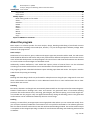
How it works?
The software includes standard graphical user interface for Windows. You can enter commands either by
clicking buttons on the main toolbar or by typing commands in the command line located at bottom. Detailed
descriptions of all commands are provided further in this manual. If you hold the mouse over a button, a
tooltip appears with a short description of the respective command.
Working with files
Beam Expert has its own file format which is used to save program data permanently on the disk. Input file
extension is *.bea. Results are stored into *.bea.html files.
New file
Click the
button to save current data to a new file. A standard file selection dialog appears on screen.
Select or write down file path and name and click "Save".
Open a file
Click the
button to open a file from the disk. A standard file selection dialog appears on screen. Browse
for the file using the mouse or type file path and name and click "Open".
Save a file
Click the
button to save a file to the disk. A standard file selection dialog appears on screen. Select the
destination folder and file name. If file already exists you will be prompted to overwrite or change the name.
стр. 4 от 25
Beam Expert v 2.7/2014
Analysis, design and detailing of RC continuous beams
User manual
Input data
Input data is divided into several pages for convenience. You can switch between pages by clicking the
respective buttons on the main toolbar
. Use the text fields and tables inside
each page to enter data. The results are shown immediately on the drawing at the bottom.
Working with tables
Most of the input data is entered in tables. You can use the following commands to work with all tables inside
the program:
Insert new row – press Ins key or “+” button. When you go to the end of the last row and press Enter,
a new row opens automatically;
Delete last row – press Backspace or “−” button. Some tables are with fixed dimensions and you
cannot add or remove rows;
Move the current focus with one cell – press arrow keys , , , ;
Move the focus to the first or the last row – press Page Up, Page Down, Home, End;
Edit current cell contents – press F2 or just start typing – an input box is opened automatically;
Finish cell edit – press Enter or arrow key – the input box is closed and changes are stored into the
cell;
Cancel cell edit – press Esc – the input box is closed and changes are discarded. The original contents
remains in the current cell;
Delete cell contents – press Del – the contents of all selected cells is cleared;
Select a range of cells – the first method is to use the keyboard – select the first cell, hold Shift and
press arrow keys or Page Up, Page Down, Home, End to move to the cell at the other corner of the
area. Alternatively, you can click with the mouse at the first corner, hold Shift and click at the
opposite corner;
Copy the contents of the selected cells – press Ctrl+C;
Paste into the selected cells – press Ctrl+V;
You can copy from and paste to the same or other tables as well as external programs like Word, Excel, etc.
If you try to paste a range of cells which area is greater than the area of the destination cells, you will receive
a warning. This is necessary to avoid unwanted data overwriting.
Design code
Design Expert is compatible to Eurocodes, mainly EN 1992-1-1 and EN 1998-1-1. It is applicable to most
countries as far as you can define your own material properties, partial safety factors, loads and some other
important parameters. Detailed description of all design methods and formulas used in this program is
provided further in this manual.
стр. 5 от 25
Beam Expert v 2.7/2014
Analysis, design and detailing of RC continuous beams
User manual
Materials
Material and section properties are entered on the first page of the program.
It is active at startup by default. If you have moved to another page, you can
always go back with the
button.
You have to enter concrete grade
and steel grades for main
and shear
reinforcement. Also, you can specify a symbol (N, Ø, ect.)
to be used for bar labelling in the drawings. Characteristic and design values
for material properties are predefined in tables. Concrete compressive and
tensile strengths are additionally multiplied by the sustained loading factors
cc and ct. They should be defined separately in the respective fields since
they are not included in the table values.
Material tables
You can open the material tables by clicking the
button. A dialog containing both concrete and
reinforcement tables appears on screen. You can modify values, add and remove rows by clicking the „+” and
„-” buttons, respectively. Finally you should press “Save” to save changes and close the dialog. If you want to
discard changes, press “Exit” and you will return to the main window.
Material tables are common for the whole computer. Any changes you make will reflect all Design Expert
modules and input files.
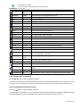
Material data to Eurocode
Concrete
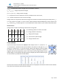
Design Expert includes the following concrete grades according to EN 1992-1-1, Table 3.1:
Name
Ecm fck,cube
GPa
MPa
fcd
fctd
fck
fctk,0.05
MPa
MPa
MPa
MPa
εc2
εcu2
C12/15 27.0
15.00
8.00 0.73 12.00
1.10 0.002 0.0035
C16/20 29.0
20.00 10.67 0.87 16.00
1.30 0.002 0.0035
C20/25 30.0
25.00 13.33 1.00 20.00
1.50 0.002 0.0035
C25/30 31.5
30.00 16.67 1.20 25.00
1.80 0.002 0.0035
C30/37 33.0
37.00 20.33 1.33 30.50
2.00 0.002 0.0035
C35/45 34.0
45.00 23.33 1.47 35.00
2.20 0.002 0.0035
C40/50 35.0
50.00 26.67 1.67 40.00
2.50 0.002 0.0035
C45/55 36.0
55.00 30.00 1.80 45.00
2.70 0.002 0.0035
C50/60 37.0
60.00 33.67 1.93 50.50
2.90 0.002 0.0035
The following symbols are used in the above table:
Ecm – concrete secant modulus of elasticity;
fck,cube – characteristic cube strength;
fck – characteristic cylinder strength;
стр. 6 от 25
Beam Expert v 2.7/2014
Analysis, design and detailing of RC continuous beams
User manual
fctk,0.05 – characteristic tensile strength with 5% probability of failure;
fcd = cc fck/c – design compressive strength;
fctd = ct fctk,0.05/c – design tensile strength;
εc2 – compressive strain at maximum stress for parabolic-linear stress-strain;
εcu2 – ultimate compressive strain at concrete edge.
Design values for compressive and tensile strengths in the table are determined for partial safety factor c =
1.5. They still do not include cc and ct factors which should be defined additionally. Some countries use
cc = 0.85 and ct is usually equal to 1.0. You should look for these values in your national annex document.
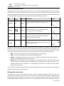
Reinforcement
Design Expert includes the following reinforcement steel grades:
Name
Es
fyd
fyk
GPa MPa MPa
εyd
The following symbols are used in the table:
Es – design modulus of elasticity;
B220
200
191
220
0.01
B250
200
217
250
0.01
B420
200
365
420
0.01
fyk – characteristic yield strength;
B460
200
400
460
0.01
εyd – design ultimate strain.
B500
200
435
500
0.01
fyd – design yield strength;
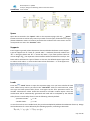
Cross sections
Cross section data is entered in the “Sections” table. Shapes can be “Т”, inverted “T”, “I”,
“L” or inverted “L”. Dimensions are noted as shown in the picture on the right. For „L” or
inverted “L” shapes enter „L” in the first column. Sections are aligned to their top edges
by default. You can move a section up or down by entering, respectively, positive or
negative value for the eccentricity „ey, cm”. That is how, you can align sections to their
bottom edges, in case of beam with slab at bottom. Sample input data for different types
of cross sections is provided in the table below:
Pictures of all sections in the table and their dimensions are displayed in the bottom half of the main window.
The result from the above input will look as follows:
стр. 7 от 25
Beam Expert v 2.7/2014
Analysis, design and detailing of RC continuous beams
User manual
Spans
Span data is entered in the “Spans” table on the respective page. Click the
”Spans”
button to activate it. Add as many rows as you need. For each span, fill the effective length
(distance between centers of columns) and select the number of the cross section. It must
corresponds to a row in the “Sections” table.
Supports
Enter support type and column dimensions above and below the beam at each support.
Types of supports are F – fixed, P – pinned and C – cantilever (free end). Column size
”hci“ is along the beam and “bci“ is across the beam. If you enter positive value for
column height “Hci”, the respective column stiffness will be included in the analysis. The
beam will be calculated as a part of frame. In this case, the defined support types refer
to column ends. Index i = 1 refers to the lower column and index i = 2 - to the upper one.
Loads
Press the
”Loads” button to open the respective page. First you have to define all load
cases. Add as many rows as you need in the “Load Cases” table. For each load case, select
case type and enter partial safety factor. Load types can be P for permanent and V for
variable. Characteristic values should be entered for all loads in Beam Expert. Then ULS
combination will be automatically generated and loads will be multiplied by the defined
safety factors. Partial safety factors have the following values by default:
- permanent loads:
- variable loads:
γG = 1.35
γQ = 1.50
In case of more than one variable loads, they must be multiplied by additional combination factors ψ. Design
load combination for ULS is defined by the following equation, according to Eurocode:
ΣγG·Gkj "+" γQ,1 Qk,1 "+" ΣγQ,i·ψ0,i Qk,i;
стр. 8 от 25
Beam Expert v 2.7/2014
Analysis, design and detailing of RC continuous beams
User manual
Variable load with major contribution to the internal forces is assumed to be leading “Qk,1”. It is multiplied
by partial safety factor “γQ,1” only. All remaining loads should be multiplied by γQ,i·ψ0,i. Values should be
entered in the “Factor” column in the table. You can find load combination factors in your national Annex.
Load values for each span and case are entered in the
„Loads” table. Loads can be distributed or concentrated
forces and moments.
You can add as many rows as you need by clicking the “+”
button. Enter span number in the first column. If you leave it
empty, the load will be applied to all spans. If the load should
act on several spans, you can enter their numbers, separated
by commas (e.g. “1,2,4,7”). Enter load case number in the
second column. Double click to open a drop down list with possible values. You can have many loads in one
load case.
Distributed loads can be uniform or linear. You have to enter left and right values q1
and q2 as shown in the picture. When you fill q1 and press Enter, the value is copied
automatically into q2. That helps you to enter uniform loads more quickly. For linear
loads, set different value of q2. Loads can be partially distributed along spans. In this
case, you have to define additionally:
x – starting distance from the edge of the left column;
L – length of load distribution.
If you leave x and L empty, the load will be distributed along the full span clear length. If you enter x > 0 and
L = 0, then load will start at x and continue to the edge of the right column. It is the same if you enter L to
be greater than the remaining of the span.
Concentrated forces and moments are defined by load values „F” and „M” and distance „A” from the left
column edge. You can enter distributed and concentrated loads in the same row as long as they act in the
same span and in the same load case.
Loads can be located only within clear span length and not within columns.
If the beam is part of an anti-seismic frame structure, you can enter seismic moments M1
and M2 at both ends of each span. They can be obtained separately by seismic analysis
software using finite element model. Values should be calculated at column centers. Signs
are neglected and only absolute values for M1 and M2 are important. The program
automatically creates two combinations that correspond to both directions of seismic
loading: right (−M1, +M2) and left (+M1, −M2). Finally it calculates envelope diagrams,
including permanent and variable loads in seismic design situation. That is why, you have
to define the ψ2 combination factor for variable loads. Permanent and seismic load
combination factor is always 1.00.
Results
Analysis
Only buttons for input pages are shown in the main toolbar before running the analysis. When you finish all
the input, press the
button to start the analysis. Buttons for output pages are loaded and internal forces
стр. 9 от 25
Beam Expert v 2.7/2014
Analysis, design and detailing of RC continuous beams
User manual
diagrams are displayed on screen. You can always go back to the diagrams by pressing the
button.
“Diagrams”
Elastic analysis of the beam is performed by using matrix method (direct stiffness method). Each span is
divided into 12 segments. Element stiffness is calculated using cross section properties and mean secant
modulus of elasticity of concrete Ecm. Supports are located at column centers and rigid end zones are added
between column edges.
The program automatically generates three load combinations according to Eurocode:
ULS (Ultimate Limit State) -
ΣγG·Gkj "+" γQ,1·Qk,1 "+" ΣγQ,i·ψ0,i·Qk,i;
SLS (Serviceability Limit State ) -
ΣGkj "+" Qk,1 "+" Σψ0,i·Qk,i;
Seismic -
ΣGkj "+" Σψ2,i·Qk,i "+" AEd.
Internal forces are calculated using the ULS and seismic combinations while deformations and crack widths
are calculated by the SLS combination.
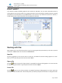
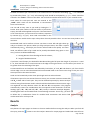
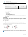
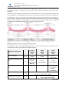
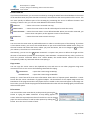
Internal forces
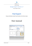
Bending moment diagram M and shear force
diagram V are obtained as a result. The most
unfavorable distribution of variable loads is taken
into account and envelope diagrams are created. If
you have seismic loads, the final diagram is created
by enveloping ULS and seismic combinations.
Seismic load
Permanent and variable loads
Seismic combination
ULS combination
Final diagram
Capacity design
You can use Beam Expert to obtain the capacity values of internal forces and include them into the
reinforcement design. Before that, you have to design and draw the reinforcement using the initial values as
a first iteration. Click the
“Reinforcement” and
“Drawing” buttons to design and draw the
reinforcement and select bar diameters and counts. Then go back to internal forces diagrams by clicking the
“Diagrams” button and you will see the capacity moments and shear forces. They are labeled right below
and above beam axis at both ends. They are calculated only if medium (DCM) or high (DCH) ductility class is
selected.
Capacity bending moments
Capacity values of bending moments MRd,t and MRd,b are calculated for top and bottom reinforcement,
respectively, at both ends of each span. They represent the maximum bending moments that a cross section
can take with the selected reinforcement. In general case of a Tee section, they are calculated as follows:
MRd = Fs∙z, where
Fs = fyd∙As,prov
– tensile force in main reinforcement;
z = d – 0.5(Abf∙hf + b∙x2)/(b∙λx + Abf)
– lever arm of internal forces;
стр. 10 от 25
Beam Expert v 2.7/2014
Analysis, design and detailing of RC continuous beams
User manual
λx = (Fs/fcd − Abf)/b
– compression zone depth;
Values of Abf and b are determined as follows:
Tee cross section
Rectangular cross section
If Fs > bf∙hf∙fcd
neutral axis in web
If Fs ≤ bf∙hf∙fcd
neutral axis in flange
Abf = 0; b = bw
Abf = (bf − bw)∙hf; b = bw
Abf = 0; b = bf
bw – web width;
bf – width of compressed flange;
hf – thickness of compressed flange;
d = h – 5 cm – effective depth;
h – section height;
fyd – design yield stress;
fcd – design compressive strength of concrete;
As,prov – area of reinforcement at the respective side (top or bottom), that is sufficiently anchored
behind column edge.
Soft storey check
According to Eurocode 8, columns in anti-seismic frame structures should be designed with greater bending
capacities than the adjacent beams. Capacities are determined so that the following condition to be satisfied
in each beam-column joint:
ΣMRc ≥ 1.3ΣMRb, where
ΣMRc – sum of bending capacities of columns above and below the joint;
ΣMRb – sum of bending capacities of all beams connected to the joint in the selected plane.
Design check must be performed for both directions of seismic loading. Capacity moments at the respective
sides should be taken for each direction:
Capacity moments for beams MRd,t and MRd,b can be calculated by Beam Expert (see the above chapter).
Capacity moments for columns can be calculated using PMM Expert, which is another Design Expert module.
For convenience, you can export diagrams with capacity values to AutoCAD or ZWCAD by using the
or
buttons.
стр. 11 от 25
Beam Expert v 2.7/2014
Analysis, design and detailing of RC continuous beams
User manual
Capacity shear forces
According to Eurocode 8 design shear forces have to be determined using bending capacity moments at ends
of each span. Capacity shear force diagrams are generated. Values are displayed above and below beam axis
at both ends. They are calculated as follows:
at the left end (1):
at the right end (2):
VEd,t1 = V0,1 + VE,t
VEd,t2 = V0,2 + VE,t
VEd,b1 = V0,1 + VE,b
VEd,b2 = V0,2 + VE,b
where V0,1 and V0,2 are design shear forces due to vertical
loads in seismic load combination:
ΣGkj "+" Σψ2,i ·Qk,i
VE,t = (M1d,t + M2d,b)/lcl
VE,b = (M1d,b + M2d,t)/lcl
Moments M1d,t, M2d,t, M1d,b and M2d,b are the increased values of the capacity moments at both ends. They
are determined by the following equations:
M1d,t = γRd∙MRd,t1∙min(1;ΣMRc,1/ΣMRb,1)
M2d,t = γRd∙MRd,t2∙min(1;ΣMRc,2/ΣMRb2)
M1d,b = γRd∙MRd,b1∙min(1;ΣMRc,1/ΣMRb,1)
M2d,b = γRd∙MRd,b2∙min(1;ΣMRc,2/ΣMRb2)
According to Eurocode, the factor γRd is assumed to be 1.0 for DCM and 1.2 for DCH. Capacity moments
MRd,t1, MRd,t2, MRd,b1 and MRd,b2 are calculated for the actual reinforcement at the respective end of the
ΣMRc,i/ΣMRb,i is the ratio of sums for bending capacities of columns and
beams connected to the current joint. If ΣMRc,i > ΣMRb,i, ratio is assumed to be equal to 1.0.
span as described previously.
After the capacity shear forces are calculated, you can include them into the reinforcement design. Click
again
“Reinforcement” and
“Drawing” to obtain the final results.
Deflections and crack widths
You can use Beam Expert to calculate elastic and inelastic deformations and crack widths of beams. SLS load
combination is used for these calculations.
Elastic deflections
Click on the “Deflections”
button immediately after the analysis to see a diagram of elastic deflections.
They are determined using mean elastic modulus of concrete and gross area properties of concrete section
without reinforcement.
Inelastic deflections
In order to see the inelastic deflections, go to „Reinforcement”
and „Drawing”
pages first by clicking
the respective buttons and then go back to „ Deflections”
. Calculations are performed for SLS including
nonlinear concrete characteristics such as creep, shrinkage, cracks and actual reinforcement. For each
section, crack opening check is performed and crack widths are calculated if necessary.
For calculation of inelastic deflections, each span is divided into 12 elements. Top and bottom reinforcement
is determined for each element. Crack opening bending moment is calculated. The element is classified as
стр. 12 от 25
Beam Expert v 2.7/2014
Analysis, design and detailing of RC continuous beams
User manual
cracked if design bending moment is greater than crack opening moment or as non-cracked otherwise.
Nonlinear stiffness is calculated for cracked or non-cracked element. Then analysis is restarted and
deflections are calculated as a result.
Reinforcement design
Beam Expert performs bending and shear design according to Eurocode. The same procedures are used as in
the RC Expert module. You can find a detailed description of the design procedures in the RC Expert user
manual. Calculations are performed for all sections along each span. Required reinforcement area diagrams
are obtained for main (top and bottom) and shear reinforcement. You can start the design procedure by
clicking the „Reinforcement ”
button .
Effective depth for bending design is assumed to be d = h − 5 cm. Shear design is performed for two leg links.
Reinforcement area Asw [cm2/m] is provided for one leg. Additional tensile force Ft from shear design is
calculated in main reinforcement, according to Eurocode 2. It is included by widening the main reinforcement
diagram.
Report
You can generate a detailed report in HTML format for each task by clicking the
"Results" button. The
report is opened in a web browser (Internet Explorer by default). Most office programs like MS Word can
edit html files. Report filename is data_file_name.html.
It comes together with a folder data_file_name.html_files. Always keep the report file and the folder
together, otherwise pictures and formatting will be lost.
Detailing and drafting
Beam Expert is capable of automated reinforcement detailing. After that you can export ready to use
drawings directly to AutoCAD or ZWCAD. Unlike purely detailing software where you have to enter count,
diameter, shape and dimensions for each bar or shear link, Beam Expert can generate all of the above data
automatically, based on the required reinforcement diagrams. Eurocode detailing requirements are
automatically included, such as minimum and maximum reinforcement ratios, bar and link spacing, anchoring
and splicing, bending radiuses. Eurocode 8 requirements for seismic design are also included. That allows you
to generate detailed reinforcement drawings that correspond to code requirements with minimum input
data.
You can start reinforcement detailing and drawing by clicking the „Detailing”
The “Settings” dialog appears on screen where you can do the following:
button on the main toolbar.
-
Select options for reinforcement detailing and drawing layout;
-
Automatically generate reinforcement bars and shear links by covering the required reinforcement
diagrams;
-
Modify counts and diameters for top, bottom and shear reinforcement in each span;
-
Generate the drawing with the selected reinforcement.
стр. 13 от 25
Beam Expert v 2.7/2014
Analysis, design and detailing of RC continuous beams
User manual
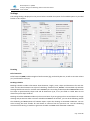
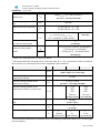
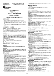
Settings
The settings dialog is displayed on the picture below. Detailed description of all available options is provided
further in this chapter.
Drawing
Bill of materials
Bill of materials (BOM) includes weight of reinforcement (kg), total and by bar size, as well as concrete volume
(m3) and formwork area (m2).
Bending schedule
Bending schedule includes information about diameter, length, count, shape and dimensions for each bar
mark. You can select between two styles of scheduling: “Standard” and „BS8666”. The standard style includes
drawings with dimensions for each bar mark. BS8666 style is according to British Standard BS8666:2005. Each
bar shape is represented by shape code and all dimensions (A, B, C etc.) are filled in a table. Bars are not
drawn except for shape code 99.
Bending schedules and BOM include only the current beam. If you are going to have several beams in a single
drawing and you want to make a common schedule and BOM for all of them, you can do the following: Switch
the scheduling and BOM options off in Beam Expert. Export the drawings to AutoCAD or ZWCAD+. You can
select starting bar mark number for each beam to continue from the previous one. Use the scheduling
command from RC Plug-in module to generate schedule and BOM inside AutoCAD or ZWCAD+.
стр. 14 от 25
Beam Expert v 2.7/2014
Analysis, design and detailing of RC continuous beams
User manual
Rounding
You can specify rounding steps for bar dimensions and total bar lengths. They are 5 mm and 25 mm by
default. Links are not affected by this options. They are always rounded to an integer number.
Numbering
Enter starting mark numbers for shear links and bars separately. You can continue the numbering from the
previous beam.
Scale
You can set different scales for elevations and sections. Specify text size in millimeters as it should appear on
the printouts. Actual text size on the screen is automatically calculated according to the scale. You can also
select different drawing units (mm, cm or m).
Concrete cover
Concrete cover is defined as the distance between concrete surface and surface of shear links and bars,
respectively. Actual distance from bars to concrete edge is taken as the greater value of:
- cover to main bars or
- cover to shear links + link diameter.
External CAD
You can export the drawing to different CAD systems. You have to select the preferred system (ZWCAD+ or
AutoCAD) in the combo box. See “Export to AutoCAD and ZWCAD” further in this manual.
Ductility class
Detailing requirements for different ductility classes are included. The program automatically applies the
requirements for the selected ductility class during the detailing process. You should select one of the
following possible values from the combo box: DCL, DCM or DCH. For more information, see "Detailing
requirements to Eurocode 2 and Eurocode 8" bellow. If you need to design to Eurocode 2 only, select DCL.
Otherwise, Eurocode 8 is applied.
Detailing
The program automatically selects counts and diameters for bars and shear links based on the required
reinforcement diagrams obtained by the design. This is performed after the settings dialog is opened for the
first time or when you click the “Generate” button.
You can set limits for diameters which can be used by the program by setting the “Preferred diameters”
option. For main reinforcement select minimum and maximum diameters [Ømin; Ømax]. Lower values of Ømax
will increase the number of bars. For shear links you can select one preferred diameter Ø. It is used for the
entire beam, if possible. The program will use larger diameter only if link spacing gets lower than the
minimum.
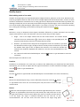
You can select whether to use curtailment separately for bottom, top or shear reinforcement. Without
curtailment, all bars in the span (or above the support) have equal lengths and count is calculated for the
maximum required area. Link spacing is calculated also for the maximum shear reinforcement area and it is
uniform along the whole span. The standard length for top bars above supports (without anchoring) is ¼ of
стр. 15 от 25
Beam Expert v 2.7/2014
Analysis, design and detailing of RC continuous beams
User manual
the longer adjacent span. If top reinforcement diagram goes outside this zone, it is covered by the top
reinforcement in spans. For cantilever spans, top bars above the support are projected to the free end of the
cantilever.
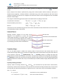
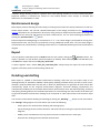
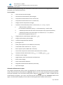
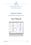
When the curtailment option is selected, part of reinforcement bars (≥ 50%) is extended at full length and
the remaining part is curtailed within the zone that is not covered by the capacity of the first part. Shear links
are divided into 2 zones – with denser spacing within end quarters of the span and sparser in the middle half.
With curtailment, quantity of steel gets lower, but the number of different bar marks increases and detailing
becomes more complicated. It is appropriate for larger and more heavily loaded beams. Example of
reinforcement curtailment with Beam Expert is shown on the picture below:
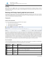
Detailing requirements to Eurocode 2 and Eurocode 8
All parameters, used for automated detailing of beams are listed in the table below. References to the
corresponding sections of Eurocode are provided in brackets.
Longitudinal reinforcement
Minimum diameter
Minimum tensile reinforcement
ratio
Minimum top reinforcement in
spans
d bL,min
min
DCL
Non-seismic
element
EC2
DCM
Seismic
element
EC8
10 mm
12 mm
0.26∙fctm/fyk
0.0013
fctm/2fyk
fctm/2fyk
(5.4.3.1.2 (5))
(5.5.3.1.3 (5) a)
(9.2.1.1 (1) and
NA.2.74)
DCH
Seismic
element
EC8
14 mm
(5.5.3.1.3 (5))
2N14,
-
-
( 5.5.3.1.3 (5) b)
0.25A's,cr
(5.5.3.1.3 (5) c)
Maximum reinforcement ratio
Maximum ratio for tensile
reinforcement in critical zones
0.04
max
cr,max
(EN 1992-1-1, 9.2.1.1 (3) и NA.2.75)
-
‘cr + 0.0018 fcd/( sy,d fyd)
(5.4.3.1.2 (4) и 5.5.3.1.3 (4))
стр. 16 от 25
Beam Expert v 2.7/2014
Analysis, design and detailing of RC continuous beams
User manual
Minimum clear spacing
between bars
мax{d bL,max, dg + 5 mm, 20 mm} 1)
amin
(EN 1992-1-1, 8.2 (2) и NA.2.70)
Maximum spacing to centers of
bars
Mandrel diameter for bending
amax
250 mm
dm
For Ø ≤ 16 mm - d m = 4Ø
For Ø > 16 mm - d m = 7Ø
Anchorage length
lbd
fbd = 2.2512fctd, lb,rqd = dL/4∙sd/fbd
lbd = 12345 lb,rqd > lb.min
lb.min = max{0.3lb,rqd,10dL, 10 cm}
Extension of bars in the next
span after an internal joint
Maximum ratio of bar diameter
to the size of the column
section
1)
-
(5.6.1 (3))
lcr
-
dbL
hc
l bd + 5dbL
(5.6.2.2 (4))
7.5fctm/Rd fyd∙(1 + 0.8d) – at end joints2)
7.5fctm/Rd fyd∙(1 + 0.8d)/(1 +
0.75kD'/max) – at internal joints
(5.6.2.2 (2))
Gravel size is asuumed to be dg = 20 mm by default.
Normalized axial load is assumed to have a minimum value of d = 0.1, conservatively. There is no data for
internail forces in connecting elements when using Beam Expert standalone.
2)
Shear reinforcement
Minimum reinforcement
DCL
s min
Maximum spacing between shear
reinforcement centers
s max
(5.4.3.1.2 (6) a and 5.5.3.1.3 (6))
50 mm
0.75d (1 + cot)
(EN 1992-1-1 9.2.2 (6) и NA.2.80)
Maximum spacing between shear
reinforcement centers in critical zones
s cr,max
-
Distance from first shear link to column
edge
Anchoring length inside the concrete
DCH
6 mm
d w,min
Minimum spacing between shear
reinforcement centers
DCM
hw/4
24dw
8dbL
225 mm
hw/4
24dw
6dbL
175 mm
(5.4.3.1.2 (1) b)
(5.5.3.1.3 (6))
50 mm
(5.4.3.1.2 (1) c)
10dw
lbw
Critical zone length
lcr
(5.6.1 (2))
ln/4
zone of
condensation1)
ln/4 2)
hw
ln/4 2)
1.5hw
(5.4.3.1.2 (1))
(5.5.3.1.3 (1))
1)
If you select the reinforcement curtailment option, link spacing is condensed at distance of ¼ of span length
near the supports.
стр. 17 от 25
Beam Expert v 2.7/2014
Analysis, design and detailing of RC continuous beams
User manual
2)
In order to simplify the detailing, the condensation zone and the critical zone are merged. Most unfavorable
parameters are used from both zones.
List of symbols:
fctm
– mean concrete tensile strength;
fyk
– characteristic reinforcement yield strength;
A's,cr
– compressive reinforcement area in critical zone;
'cr
– compressive reinforcement ratio in critical zone;
fcd
– design concrete compressive strength;
– minimum curvature ductility factor in critical zone = 1 + 2(q – 1)Tc/T1;
q
– behavior factor, Table 5.1.
It is assumed conservatively that q = 3.3 for DCM and q = 4.95 for DCH;
Tc
– vibration period at the end of the horizontal part of the response spectrum;
T1
– vibration period for first mode shape. It is assumed: Tc/T1 = 1.0, which is
conservative for greater values of T1;
sy,d
– design value for reinforcement yield strain = fyd/Es
fyd
– design reinforcement yield strength;
d bL,max – maximum longitudinal bar diameter;
dg
– gravel grain size;
Rd
– safety factor equal to 1.0 for DCM and 1.2 for DCH;
d
– normalized column axial load d = Ned/fcdAc;
kD
– factor equal to 2/3 for DCM and 1.0 for DCH;
’
– ratio of the compressive reinforcement anchored into the column;
max
– maximum tensile reinforcement ratio max = ‘ + 0.0018 fcd/( sy,d fyd);
d
– effective section height;
– angle between shear reinforcement and beam axis;
hw
– beam section height;
dw
– shear reinforcement diameter;
dbL
– longitudinal reinforcement diameter (minimum);
ln
– span clear length.
Selected reinforcement in spans
The program automatically selects counts and diameters for all bars and shear links based on the design
results. The procedure is started with the “Generate” button. You can review and edit the reinforcement for
each span separately. You can browse among spans using the
buttons. In order to modify the top
reinforcement at support 1, go to span 1 and click the left arrow. If you press the “Generate” button once
again, it will discard all changes you have made and will regenerate the whole reinforcement.
стр. 18 от 25
Beam Expert v 2.7/2014
Analysis, design and detailing of RC continuous beams
User manual
Drafting
When you press the “Draw” button, the entire drawing is generated and the “Settings” dialog is closed. If
you go back to the “Reinforcement” page, you will see diagrams for theoretical reinforcement area vs. actual
reinforcement area.
Working with Design Expert graphical environment
All drawings are generated in the internal Design Expert graphical environment first. There you can view,
modify and align objects before exporting them to ZWCAD+ or AutoCAD. The graphical environment includes
a basic set of commands for drawing and editing.
Commands
How to enter commands?
You can use several ways to enter a command in this program:
Type it into the command line;
Type the short version (command alias);
Press a button on the toolbar;
Alternatively, instead of typing you can select the command from a drop down list by clicking the small arrow
right to the command line. Some commands may require you to select objects or enter coordinates. You
should watch the prompt on the left side of the command line. Press enter or right mouse button to complete
a command that is running. You can cancel a command prematurely by pressing Esc or right mouse button.
Commands generate various output including error or warning messages, results and general information
intended for the user. You can find it in the output window just above the command line. You can start the
previous command by pressing Enter or Space key instead of typing it again or pressing a button.
List of commands
A list of all available commands including icons, aliases and short descriptions is provided in the table below.
You can find detailed descriptions of all commands further in this manual.
Command
Alias
Description
ZWCAD+
AUTOCAD
CAD
Export the current drawing to AutoCAD/ZWCAD+.
COPY
CP, CO
Replicate the selected objects by moving, rotating, mirroring or scaling.
COPYBITMAP
CB,
COPYBMP
Copy the current drawing as Bitmap to system clipboard where it is
available to paste in other programs.
COPYMETAFILE CM,
COPYWMF
Copy the current drawing as Metafile.
DELETE
Delete selected objects from both screen and memory.
E, D, DEL,
ERASE
стр. 19 от 25
Beam Expert v 2.7/2014
Analysis, design and detailing of RC continuous beams
User manual
DESELECTALL
DE, DESEL,
DESELECT
Deselect all objects.
DISTANCE
DI, DIST
Measure distance and angle between points.
EXIT
QUIT
Close the program and exit.
GRID
GR
Turn grid on and off.
HELP
Display user manual.
MIRROR
MI
Mirror the selected objects about a line defined by two points.
MOVE
M, MO
Move the selected objects along a vector defined by two points.
NEW
N
Create a new file.
OPEN
O
Open an existing file from the disk.
ORTHO
OR
Turn orthogonal drafting mode on and off.
OSNAP
OS
Turn object snap mode on and off.
PRINT
PR, PRN
Send the current drawing to the printer.
REDO
RE
Restore the last command after UNDO.
REDRAW
RD
Redraw the screen view.
ROTATE
RO
Rotate the selected objects about a specified center point and angle.
RTPAN
PA, PAN
Move the screen view to other part of the drawing.
SAVE
S
Save the current data to a file on the disk.
SCALE
SC
Scale the selected object with specified center point and scale factor.
SCRIPT
Save a script file (*.scr) with all AutoCAD commands ncessary to create
the current drawing in AutoCAD.
SELECTALL
A, ALL,
SELALL
Select all objects in the drawing that are not hidden or locked.
SNAP
SN
Turn snap-to-grid mode on and off.
UNDO
U
Undo the last command.
ZOOMIN
ZI, Z+
Zoom in the screen view by factor of 1.5.
ZOOMLIMITS
ZL, ZA, ZE
Zoom the screen view in order to fit all objects inside the program
window.
ZOOMOUT
ZO, Z-
Zoom out the screen view by factor of 0.5.
ZOOMWINDOW ZW
Zoom the screen view in order to fit inside the specified rectangle.
Undo wrong action or command
Click the
button or type the UNDO command.
It cancels the results from the last command and recovers the previous drawing state. You can undo only one
step back. If you need to go back further, use the other commands to recover the original drawing state.
Redo a command that has been undone
Click the
button or type the REDO command.
It repeats the last command in case it has been accidently undone. REDO must follow the UNDO command
immediately before any other command. Otherwise, the command cannot be recovered.
стр. 20 от 25
Beam Expert v 2.7/2014
Analysis, design and detailing of RC continuous beams
User manual
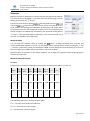
Points and coordinates input
Design Expert has its own CAD environment where you can create and modify drawings. Some commands
require the user to enter coordinates of points. You can do this by clicking with the mouse in the drawing
window or by typing the coordinates in the command line. Typing input should follow some standard formats
as described below. Coordinates can be absolute or relative to the previous point.
Type
Absolute
Input
format
X;Y
Example Description
10,5;15
Values are defined in global coordinate system
Oxy.
Relative
_Х;У
@Х;У
@25;35
Relative distances "25" и "35" to the previous
point along Х and У, respectively.
Polar
<αо;L
<45;100
Distance of "100" is measured to the previous
point at 45⁰ angle from X axis.
50
Distance of "50" to the previous point measured
towards mouse cursor.
Distance
L
Picture
Press Enter or Space after you enter the coordinates in the command line. If you want to enter points with
the mouse, you have to move the cursor to the required location and click with the left mouse button. You
can see the current coordinates of the cursor in the status bar located at the bottom of the main window.
You can use several precision tools that can help you to get the exact coordinates when clicking:
GRID – shows a uniform grid of dots over the working area of the drawing;
SNAP – rounds the coordinates to a specified step along X and Y;
ORTHO – orthogonal drawing mode. Current point is aligned to horizontal or vertical line with the
previous point depending on the mouse position;
OSNAP – gets the coordinates of an existing point in the drawing, when you move the mouse or click
over it closer than a specified range. If several points are located within the range, the closest one is
returned. When a point is snapped, an "" mark appears on the screen. It is always the same symbol
regardless the point type.
You can switch on and off the precision tools using the respective buttons on the status bar or by typing the
respective commands in the command line.
Manage the screen view
The drawing is located in the model space and it is defined in global coordinate system Oxy. Then it is
projected to the screen to certain scale. You can see only a part of the model space that is visible within the
program window. We will call this “screen view”. You can scale and move the screen view over the drawing
using ZOOM and PAN commands. That is how you can work with different parts of the drawing as necessary.
стр. 21 от 25
Beam Expert v 2.7/2014
Analysis, design and detailing of RC continuous beams
User manual
Zoom in and out
If you have a wheel mouse, you can zoom in and out by rotating the wheel forward and backward. The center
of the transformation (the point that does not move) is assumed to be the current position of the cursor. You
can move quickly to different parts of the drawing by positioning the cursor at different locations and
zooming in and out. Also, you can use some additional commands as follows:
ZOOM IN
– zooms in the screen view with one step;
ZOOM LIMITS
– zooms the screen view so that all visible objects fit inside the screen;
ZOOM WINDOW – zooms the screen view in a user defined window. When you start the command, you
have to enter two points, at the opposite corners of the window;
ZOOM OUT
– zooms the screen view out with one step.
Pan
You can move the screen view at preferred direction in order to see other parts of the drawing. If you have
a three-button mouse, you can use the middle button to pan. Press and hold the middle button, drag it to
the new location and release the button. When you press the button, the cursor changes to
and when
you release it, the old cursor is restored back.
Alternatively, you can use the
RTPAN command. It requires two points to define the length and the
direction of movement (towards the second point). Since RTPAN is a command like any other, you have to
finish the previous command before that. Unlike RTPAN, the middle button method can be used
transparently inside any command without interrupting it.
Copy screen
You can copy the screen view to the clipboard any time and insert it into other programs using Paste
command or Ctrl+V. You can use the following commands for coping:
COPYBITMAP
– copies the screen image as Bitmap;
COPYMETAFILE
– copies the screen image as Metafile.
Bitmap is a raster format file that stores information about colors of separate pixels. Metafile is a vector
format file that stores coordinates of graphical objects. The boundaries of the copied image match the
boundaries of the program window. Only objects that are visible on the screen will appear in the image. For
best results, you can stretch the program window beforehand in order to fit the drawing tightly in the window
without white spaces.
Print screen
You can send the screen view directly to the printer by pressing the
button or typing the PRINT command. A setup dialog appears on
screen. Select the required printer device from the list. You can change
paper size and orientation as well as other options by clicking the
button. Press the “Print” button to finish.
стр. 22 от 25
Beam Expert v 2.7/2014
Analysis, design and detailing of RC continuous beams
User manual
Modify objects
Block editing mode vs free mode
Graphics in Design Expert are represented by basic objects like lines, polylines, circles, texts, dimensions etc.
They are grouped in blocks in order to form more complex objects like reinforcement bars, sections or entire
elements. Each block is attached to one or more grips that are displayed as small blue boxes. By default, the
drawing is locked and you can move only entire blocks using the respective grips. This is called “block mode”.
You cannot modify separate objects within blocks. If you want to do that, you have to unlock the drawing
first. Locking and unlocking is performed by clicking the respective buttons
.
Select
Selection is a way to determine which objects should be affected by a certain command. You can select
objects either before or after the command. There are several ways to select objects:
Single – click on the object outline with the left mouse button. The outline should
intersect the cursor selection box
. If there are no object at the specified point, the
program automatically continues to window selection mode.
Window – you have to enter two points at the opposite corners of a window. If you draw
the window from left to right, all objects that fit entirely inside are selected. If you draw
the window from right to left, all objects that intersect or fit inside the window are
selected. The window is displayed with solid line in the first case and dashed line in the
second.
All – selects all visible and unlocked objects. Click the
command.
button or type SELECTALL to start the
Selected objects are redrawn in red.
Deselect
Deselection is performed in the same way as selection but additionally you should hold the Shift button.
Alternatively, you can click an object with the right mouse button. In order to deselect all objects, press Esc,
click the button or type DESELECTALL.
Delete
Click the
button or type DELETE. All selected objects are erased both from screen and memory.
Move
Moves the selected objects along a vector defined by two points. Click the
button
or type MOVE. Then enter first and second point and press Enter or click the right
mouse button.
Rotate
Rotates the selected objects around a center and with angle defined by user. Click the
button or type ROTATE. Then enter first and second point and press Enter or click
the right mouse button. The first point defines the center of rotation and the second
is for the angle. The angle is measured between the line and the +X axis
counterclockwise. You can also enter the exact value of the angle using polar
стр. 23 от 25
Beam Expert v 2.7/2014
Analysis, design and detailing of RC continuous beams
User manual
coordinate input format. Type "<α;1" in the command line instead of clicking the second point, where α
should be the rotation angle in degrees.
Scale
Scales the selected objects with a center and scale factor defined by user. Click the
button or type SCALE. Then enter first and second point and press Enter or click the right
mouse button. The first point represents the center of transformation. Scale factor is
defined as the distance between the first and the second point. Alternatively, you can
type the scale factor in the command line instead of entering a second point.
Mirror
Mirrors the selected objects about a line defined by user. Click the
button or type
MIRROR. Then enter first and second point and press Enter or click the right mouse button.
Stretch
When the drawing is unlocked, you can stretch separate objects like points, lines, polylines, dimensions,
circles, polygons and texts by “dragging” with the mouse. Select the object and click on a point (end, middle
or center point) to “catch” it. Then move the cursor to a new location and second click to “release” it. Texts
are selected and moved using their base points displayed as small circles. If you stretch a line, polyline or
polygon and you hold shift before the second click you will insert a new vertex.
When the drawing is locked then you work in block editing mode. You can move entire blocks by stretching
the respective grips. First, you have to select a grip by clicking with the mouse. Then, click again on the grip
to “catch” it, move it to the new location and click to “release” it.
Copy
Creates one or multiple copies of the selected objects using one of the available transformations (
move,
rotate,
scale or
mirror). Click the
button or type the COPY command. Select objects and press
Enter or click the right mouse button. A settings dialog appears on screen. Select method of transformation
using the icons on the top, number of repetitions and method of pointing:
First – second – click two points that define the distance between
two consecutive objects;
First – last – click two points that define the distance between the
first and the last object. All other objects will be distributed evenly
between them;
One - by - one – click a base point first. Then you have to enter
separate points to define the location of each object
independently.
Coping is not available for some objects in some modules.
стр. 24 от 25
Beam Expert v 2.7/2014
Analysis, design and detailing of RC continuous beams
User manual
Export to ZWCAD+ or AutoCAD
You can export the drawing directly to ZWCAD+ or AutoCAD by clicking the
/
button from the main
toolbar. It is always the same button, but the icon is different depending on the selected “External CAD”
option in the settings dialog. If you click the arrow next to the button you can select other CAD system
from the drop down menu. Supported versions are ZWCAD+ 2012 to 2015 and AutoCAD 2004 to 2015. If
there is an instance of ZWCAD+ or AutoCAD already running, the drawing is sent to the active document.
Otherwise, a new session is opened. Alternatively, you can type one of the following commands: ZWCAD+,
AutoCAD or just CAD.
The drawing is exported as simple polylines, texts, dimensions, lines, circles and hatches. There are no blocks
or any other complex objects, so it is easy to be modified with the standard AutoCAD commands. Current
text and dimension styles are used. If you use templates, the drawing will look as any of your other drawings.
For best results you have to define "Text Placement" to be "Over the Dimension Line, Without a Leader" in
the dimension style settings. Objects are distributed in separate layers. If the required layers do not exist,
they are created automatically. Reinforcement output is compatible to Design Expert Plug-in module. You
can use it to additionally modify and schedule the reinforcement bars.
For versions not supported by the direct output, you can create AutoCAD command script files. Click the
arrow next to the button and select “Save script file *.scr”. Enter file path and name and click “Save”. Then
you can load the saved script into ZWCAD+ and AutoCAD using the SCRIPT command or menu "Tools\Run
Script...“.
стр. 25 от 25