1
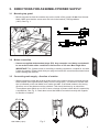
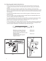
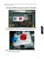
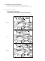
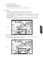
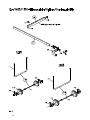
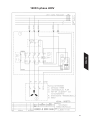
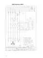
�������������� ENGLISH ����������� ���������� ���������������������������������������� ������������������������������������������� ������������������������������������� 1 CONTENTS 1. Safety instructions............................................................3 2. General instructions/Dust and Noise............................... 4 3. Directions for assembly/Power supply............................. 5 4. Functions/Transport.......................................................12 5. Operation.......................................................................13 6. Maintenance/Repair.......................................................17 7. Troubleshooting.............................................................18 8. Warranty.........................................................................19 9. Technical data................................................................20 10. Standard equipment/Optional equipment...................... 21 11. Sparepart lists/drawings................................................. 22 12. Wiring diagrams.............................................................31 13. Conformity declaration................................................... 34 14. Product marks................................................................35 Original Manual: Norwegian 507011. 2 1. SAFETY INSTRUCTIONS. 1. This machine is designed and constructed by Ernex AS and has been submitted for test and found in conformity with the Machine Directive 2006/42/EF, 2006/95/EF and EN 1870-5:2002. 2. The Health and Safety at Work places duties on designers, manufacturers and suppliers to ensure that among other things: 1. articles supplied for use at work are, so far as is reasonably practicable, safe and without risks to health during setting, cleaning and maintenance and 2. persons supplied with the articles are provided with adequate information about the use for which they are designed and about conditions necessary to ensure that they will be safe and without risks to health. 3. These duties will apply to you if you re-supply the machine by way of sale, lease, hire or hire purchase. 4. Persons who install this machine for use at work have a duty under the Health and Safety at Work to ensure, so far as is reasonably practicable, that nothing about the way in which it is installed makes it unsafe or a risk to health at all times during setting, use, cleaning and main tenance. This includes such aspects as correct assembly, electrical installation, construction of enclosures, fitting of guards and exhaust ventilating equipment. When installing this machine, consideration must be given to the provision of adequate lighting and working space. 6. The Woodworking Machines Regulations place absolute legal duty on employers and employees to ensure that guards and the Provision and use of Work Equipment Regulations and any other safety devices are securely fitted, correctly adjusted and properly maintained. 7. Repairs and maintenance must only be undertaken by competent technicians. Ensure that all power supplies are isolated before maintenance work commences. Instructions for routine maintenance are included in this manual. 8. Machine operators must have received sufficient training and instructions as to the dangers arising in connection with the machine, the precautions to be observed and the requirements of the Woodworking Machines Regulations which apply, except where they work under the adequate supervision of a person who has a thorough knowledge and experience of the machine and the required safeguards. 9. Persons under the age of eighteen years must have successfully completed an approved HSE (Health-Security-Environment) course of training before operating this machine at work, unless participating in a course of training under adequate supervision. (NB. This paragraph is only relevant to: circular sawing machines, any sawing machine fitted with a circular blade, any planing machine for surfacing which is not mechanically fed or any vertical spindle moulding machine). The saw can be used for sawing wood, plywood and chipboard. The saw must not be used on plasterboard, polystyrene and tar paper (roofing). WARNING: Safety equipment such as riving knife, blade guard and push sticks must not be removed, but have to be used! 3 ENGLISH 5. This machine is supplied complete with all necessary safeguards to enable the user to comply with the Woodworking Machines Regulations and the Provision and use of Work Equipment Regulations. Details of correct installation and use, together with guidance on fitting and proper adjustment of guards are described in this manual. 2. GENERAL INSTRUCTIONS 2.1 General safety precautions: • IMPORTANT! According to the CE-regulations, adjustable rollertable must always be used. • Ensure that there is adequate room around the saw. • For best stability, place saw on a level and even surface. • Keep sawtable, saw blade cover and area around saw free for off cuts and excessive sawdust. • When using saw indoors, the working area should be well ventilated and a dust extractor should be used. • Use good lighting, adequate hearing and eyesight protection and a dust mask. • When sawing longer pieces use the outfeed rollertable or suitable support. • Always lower top guard when sawing. • Use push sticks when ripping small materials and when the distance between saw blade and rip fence is less than 120 mm (approx. 5”). • Always switch off the motor when adjusting blade or turntable angle. • Lower saw blade when not in use. • Always use riving knife. See section 6.2 for adjusting. • Disconnect main cable when changing saw blade or performing other maintenance work. • Use only carbide-tipped saw blades which is properly sharpened. Never use a cracked or deformed saw blade. • Ensure that the saw blade cover is closed after saw blade has been cleaned and/or changed or if riving knife has been changed or adjusted. • Worn aluminium edging strips in turntable should be replaced. Dust and Noise Dust and noise measurements have been performed for work with the materials and sawblades for which the machine is intended (see Section 1 Safety Instructions). Measurement uncertainty is related to local conditions and can vary with the saw blade/transmission characteristics. Follow the maintenance instructions (see Section 6 Maintenance/ Repair Ear protection must be used, and a dust mask is recommended For indoor use, the machine must be connected to an extractor that provides a minimum air speed of 30 m/s i.e. 1.8 kPa. 4 3. DIRECTIONS FOR ASSEMBLY/POWER SUPPLY 3.1 Mounting top guard • Mount top guard so that the wooden strip on the inside of the guard is 3 mm from the saw blade. Make sure that the screw enter the hole in the bracket (1203)/guardarm (1603). See Fig. 1. 3 mm (1/8") Fig. 1 • Saws are supplied with standard plugs (EU). Any extension cord being used should be an earthed cable with a conductor cross-section of 2.5 mm2. Max length 20 m. IMPORTANT! The 3-phase motor is according to existing regulations, coupled for use with 5-pins wire supply. Please check that your plug and socket are connected as shown below before starting the machine. 3.3 Connecting main supply - direction of rotation • When connecting a saw with a three-phase motor to the mains, check to see that the saw blade rotates in the right direction (away from the riving knife). The direction of blade rotation is indicated on the saw blade cover under the table. If the blade rotates in the wrong direction, two of the phases must be switched. This should be done by an electrician. Three-phase saws which run on 400 V have a change of phase switch which is operted by a screwdriver. See Fig. 2. Check also to see that blade is mounted correctly with regards to direction of rotation. 3P+N+ S2 T3 R1 N Kobl. 400V (5 pins) Fig. 2 5 ENGLISH 3.2 Mains connection 3.4 Mounting guide bar/adj. table/roller box • Mount the guide bar onto the brackets and lock with locking handle C as shown in fig. 3. (The fig. shows Norsaw 1603). The sketch below shows the placing on the different models. • Normally, it will not be necessary to adjust the roller box bearings. If the need arises, however, loosen bearing clamp screws under the roller box and adjust bearings with screws E fig. 3b, until roller box moves freely. Tighten first locknuts and then bearing clamp screws after adjusting. • Unscrew stop screw B and slide the roller box D onto guide bar. Refasten stop screw as shown in fig. 3b. • Set up the support trestle and slightly adjust the height. Mount the adjustable table to the roller box with the enclosed mounting screws. • For height adjustment of the roller box use screws F fig. 3, and use the long fence to bring the roller box flush with the turntable fig. 4a. Adjust the height of the support trestle. • Mount the fence as shown in fig. 4a and see section 3.7 • Turn the turntable to 90° (cutting), adjust the angle of the roller box with the mounting screw F. Lock the saw blade at maximum height. and use a square between the sideplate of the roller box and the saw blade to check that the angle now is 90° fig. 4b. 1 2 3 4 5 Brakettene monteres i flg. hull: Montera fästena i följande hål: Brackets should be attached in the following holes: Montieren der Halterungen in folgende Löcher: 1203 1 & 4 1603 2 & 5 1500 1 & 3 � B ������ � � ������� F C Fig. 3 ������� 6 � C Fig. 4 a 3.5 Fig. 4 b Mounting short work support • Mount short work support as shown in fig. 5. • Mount rollers approx. 1 mm higher than saw table (at same level as the turntable.) ENGLISH M10 x 20 Fig. 5 3.6 Assembly and adjustment of infeed table with support trestle Set up support trestle L (fig. 2) and adjust at approximate height. Attach the table to the rollerbox B (fig. 1) with the 8mm screws and nuts G. Don't tighten excessively. To correct the level of the rollerbox in line with the table you have to screw and press the outer bolts H on the rollerbox against the end of the table. Tighten the longer screw G on the handle side first. Use the long fence as ruler (fig. 3). (Don't touch the inner bolts). Assembly of outfeed table with board support. Attach the rollertable to the saw as shown in fig. 4. Mount the board support (fig. 5). The manufacturer reserves the right to make modifications. 7 A G M8x45 L F H B Fig. 2 F A G M8 x 35 Fig. 1 0 Fig. 3 Fig. 5 M10 x 16 8 Fig. 4 3.7 Mounting aluminium rip fence on infeed table • Screw mounting brackets C to infeed table as illustrated in fig. 6. • Mount hinged extension stop F into the fence from rear end by sliding guide nut G into slot. Insert locking handle D fig. 7 • Turn the turntable to 0° and set the sawblade in raised position. Use a square to adjust the guide bar until the rip fence is at a 90° angle to the saw blade (fig. 3 and 3a). • Mount hinged extension stop F on rip fence by sliding guide nut G into end of slot (fig. 7). Insert the locking handles D and guide nut G in the alu.profile. • To calibrate rip fence scale, turn turntable to 0° (as for cross-cutting), raise saw blade and lock in raised position. Move rip fence lengthwise until the end of the fence is 235 mm (fig. 8 and 9) from the teeth of the saw blade. Lock fence in place with handles D (fig. 6). Set extension stop and check accuracy of rip fence setting by cutting a test piece. When rip fence adjustment is correct, attach pointer H to the side of the table as shown in fig. 8 and 9. The pointer indicates the correct position of the end of the rip fence, making it easier to return the rip fence to this position. The indicator is mounted in different directions on models 1203 and 1603, see fig. 9 for MaxiCut 1500. • Turn turntable to 90° and slide the rip fence to the left until it lies alongside the saw blade. Adjust pointer B so that it points to 0 on the guide bar (fig. 4). • Attach brackets K as shown in fig. 12 by sliding their guide nuts into the bottom slot on the fence. Position the guides 1550 mm and 2600 mm respectively from the end of the rip fence closest to the saw and tighten screws, ensuring that they are centred precisely on the fence. • Attach locator pin J as shown in fig. 12 by sliding its guide nut into the slot on the rear of the rip fence. Place the rip fence on the outfeed table frame, engaging pin J in the locator holes. To calibrate rip fence scale, turn turntable to 0° (as for cross-cutting) and slide rip fence lengthwise until the end of the fence is 150 mm from the teeth of the saw blade. Tighten locator pin screws. Set extension stop and check accuracy of rip fence setting by cutting a test piece. • Mount hinged extension stop F on rip fence by sliding guide nut G into slot (fig. 7). 9 ENGLISH 3.8 Mounting aluminium rip fence on outfeed table. � � ������� ������ C � � Fig. 6 ������ 1603 D H H 1203 Alu. 235mm F G D Fig. 7 H Fig. 8 � 1500 ������ Alu. 235mm ������� ������� Fig. 9 10 ������� � Model 900018 has a different switch combination that is changeable between 230 and 400V. Please see wiring diagram. Norsaw 900018 w/special switch 230-400V ENGLISH Saw equipped with switch box changeable between 230V and 400V. NB! - Can’t be used with the Dust Extractor! NB! Make sure that the switch knob is connected to the correct power supply. 21.10.09 JH/rhm 11 4. FUNCTIONS 4.1 Starting and stopping motor An On/Off switch A is located on one of the legs. A cover which can be locked with a padlock is mounted over the switches. See Fig. 4. Incorporated into the switch is a zero-voltage switch which prevents the motor from starting unexpectedly after a power-out. If the motor is overloaded, the built-in overload feature will disconnect the power. After a short cooling-off period the motor may be started again by pressing the start button. Avoid overloading the motor. 4.2 Raising and lowering saw blade The saw blade is raised and lowered by means of the elevation arm illustrated in B, Fig. 4. The blade may be locked at the desired height by means of the elevation locking clamp illustrated in B, same figure. 4.3 Tilting saw blade The saw blade must be in low position when adjusting tilting angle. Loosen tilting locking clamp C to tilt saw blade from 0° to 45°. See Fig. 4. The angle of tilt is indicated on the curved scale under the table. 4.4 Turning turntable The turntable may be turned horizontally from 0° (ripping) to 135°. The angle is indicated on a scale on the table. Lock turntable in desired position by means of locking screw D or locking stop handle E at the front of the saw table. See Fig. 4. Model 1603 has pre-stops at 0° -22,5° -45° -90° and 135°. Model 1203 has pre-stops at 0° -45° and 90°. �� �� � When lifting using a crane, attachment straps can be placed diagonally around the legs (1203) or in the hooks in front (1603). � Wheels can be supplied as an option. � � � Fig. 4 ���� � 12 5. OPERATION 5.1 Crosscutting • There are two methods for making crosscuts (with the turntable at 90°). A • Hold material against fence and raise saw blade to make cut. See Fig. 5. B • Raise saw blade to desired height and lock into place. Place material against fence behind saw blade and feed material into saw blade by pulling fence. See Fig. 6. CAUTION! Crosscutting can only be done with sawblade in a 90° angle. 90˚ 90˚ Fig. 5 ENGLISH Never saw more pieces at one time than can be held securly against the fence. 90° 90° Fig. 6 13 5.2 Bevelled crosscutting (tilted blade) • Tilt saw blade to desired angle and tighten locking clamp. • Place material against fence and cut by lifting saw blade. See Fig. 7. 5.3 Angled crosscutting • Set saw blade in vertical position. • Turn the turntable to desired angle in relation to fence and lock. • Hold material against fence and cut by lifting saw blade. See Fig. 8. Fig. 7 Fig. 8 Fig. 9 14 5.4 Compound angle cutting • Set turntable as for an angled crosscut. • Tilt saw blade to desired angle and lock. • Hold material against fence and cut by lifting saw blade. See Fig. 9. 5.5 Ripping • Lock saw blade at desired height, and turn parallel to roller table fence. • Lock fence at desired distance from saw blade to obtain width required. • Feed material along fence and into saw blade. Use push sticks when the distance between saw blade and fence is less than 120 mm (5”) and the remaining length is less than 120 mm (5”). See Fig. 10. • If ripping solid material which has a tendency to jam between the saw blade and the fence, position the fence lengthwise so that its end is in level with the centre of the saw blade. ENGLISH Fig. 10 5.6 Ripping with bevelled cuts • Set turntable and fence for ripping and adjust saw blade to desired vertical angle and lock. Perform operation as described in 5.5. See fig. 11. Fig. 11 15 5.7 Cutting grooves lengthwise • Set saw blade in vertical position, raise and lock at desired height and adjust turntable parallel to roller table fence. • Lock fence at desired distance from saw blade. • Feed material along fence and over saw blade, using push sticks when the distance between fence and saw blade is less than 120 mm (5”) and trailing end of material is less than 120 mm (5”) from saw blade. • Adjust fence and repeat operation until groove is the required width. See Fig. 12. 5.8 Cutting rabbets and grooves across material • Set the turntable at 90° to the fence and lock the saw blade at the desired height. • Hold material against the fence and feed it over the saw blade by pulling the roller table towards you. • Advance material slightly along the fence and repeat the operation until the rabbet or groove has the proper width. See Fig. 13. Fig. 12 Fig. 13 16 6. MAINTENANCE/REPAIR CAUTION! Make sure power supply is disconnected while performing maintenance operations. A minimum of maintenance is required to ensure satisfactory performance and a long service life. • Lubricate moving parts, linkages and the bearings carrying the turntable at regular intervals. It is also important to lubricate the moving rings at the ends of the sawblade spindle. • Check all screws and nuts regularly for tightness. • Top guard should be clean. If damaged it should be replaced. • Keep saw and saw blade cover free from sawdust. Pay particular attention to motor ventilation openings and cooling fins. • Keep saw blade clean and in order. Replace blade if there are any cracks or missing teeth. Remove resin deposits with a suitable cleaning fluid. • Check V-belt tension. • The saws are equipped with motorbrakes (except for 1203/3). If the saw blade rotates more than 10 secs. after using the stop switch, the brake must be replaced. 6.1 Replacing saw blade • To remove saw blade, use tools supplied with saw. First open saw blade cover. Hang upper cover in chain under sawtable and loosen arbor nut F. The arbor has a left-hand thread, so screw nut clockwise. Be sure to close cover when finished. See Fig. 14. 6.2 Replacing and adjusting riving knife • The riving knife must always be fitted when saw is being used. Adjust riving knife as illustrated in Fig. 14. • When replacing saw blade with a blade of a different thickness, the riving knife must be replaced as well. Loosen nuts G to free riving knife. The thickness of the riving knife should be the closest thickness under the kerf width of the saw blade. Be sure to close the saw blade cover when finished. 6.3 Replacing V-belt • To tighten v-belts, first loosen motor mounting screws. Screw H changes belt tension and screw I alters the angle of the motor in relation to the V-belts. See Fig. 15. 6.4 Replacing top guard and push sticks • The top guard and push sticks are important safety features which must be replaced immediately if damaged in any way. REPAIR Routines at repair: The machine must only be repaired by qualified electricians or authorised service work shops. Testing the brakes: The brake for the saw blade rotation should be tested regularly. The stop-time must be max. 10 secs. Start/stop the saw 10 times in a row and check the stop-time. 17 ENGLISH • Saw blade must be in lower position when being removed. F G � � Max. 2mm Max. 8 mm Min. 3 mm Fig. 14 Fig. 15 7. TROUBLESHOOTING The saw doesn’t start: * Check the power supply * Don’t use the same cable with several machines at the same time * Check that the cable isn’t too long, and that the cross-section isn’t too small * Contact an electrician The saw vibrates and is weak * Check that the blade box under the saw table doesn’t contain chips and sawdust * Check that the V-belt (s) is undamaged * Check the spindle * Check the blade for eccentricity, and that teeth are whole and sharp * Check that the motor brake is clean and that it loosens when starting up, clean it by removing the fan cover and for instance use compressed air to purify. The saw blade is heavy to lift and doesn’t go down completely * Check that nothing is stuck in the blade box * Check that the bearings in the ball jointed arm and the movable glide rings at either end of the spindle are not stuck. 18 8. WARRANTY SERVICE Notwithstanding any statutory requirements, Ernex AS provide warranty in accordance with the legislation of the customer‘s own country of residence, but in all cases for a minimum of 3 years, except for electrical parts which still has a 1-year warranty commencing from the date on which the machine is sold to the end user. Ernex AS/The importer promise to repair, or at our option, replace with like grade and quality any product determined to be faulty due to the failure of parts, material or workmanship. The warranty covers defects in material and/or workmanship only. When making a claim under the warranty, proof of purchase bearing the original date of purchase must be submitted. The repairs under warranty may only be carried out by Ernex AS, or by authorized Ernex warranty service agents or the importer. The warranty will not apply in cases of: - incorrect use, overloading of the machine or fitting non-approved accessories - use of force, damage caused by external influences, or foreign bodies - damage caused by non-observance of the instructions for use, such as connection to an unsuitable mains supply or voltage or non-compliance with the installation instructions - normal wear and tear ENGLISH The warranty also does not cover machines which have been partially or completely dismantled. 19 9. TECHNICAL DATA Norsaw 1203 Manufacturer: Model: Table: Transport height: Height w/base: Weight: Sawblade: Riving knife: Cutting height: Motor: Motor speed: Spindle speed: Peripheral speed: Cable dimension: Fuse: Extension cord: Overload protection setting: Drive belts: Noise as per 2006/42/EC: -certification: 20 Ernex AS, Norway. Norsaw 1203 520 mm x 780 mm 650 mm 850 mm 95 kg. Carbide-tipped, Z=30 Diam. 300 mm Arbor hole 30 mm Kerf width 3,2 mm Blade thickness 2.2 mm Hardened steel, standard thickness 2,5 mm 104 mm at 90° (vertical) 70 mm at 45° (tilted) Single-phase: 2 kW , 50 Hz, 110/240 V Three-phase: 1.5 kW, 50 Hz, 230/400 V 2800 rpm 2700 rpm 43 m/s with standard blade. Single-phase: minimum 3 x 1,5 mm2. Three-phase: minimum 5 x 1,5 mm2. Single-phase: 16 A time-lag fuse Three-phase: 10 A time-lag fuse 2.5 mm² recommended - Max. length 20m Single-phase: 9,3 A, three-phase: 3,4 A Single-phase: 1 V-belt XPZ 9.5 x 772 QP Three-phase: 2 V-belts XPZ 9.5 x 772 QP No-load: 83.6 dB Loaded: 87.5 dB Certified by Dansk Teknologisk Institut, Aarhus Identification number: 0396, approval certificate number TI-09-MD-0310 -certification: Ernex AS, Norway Norsaw 1603 930 mm x 640 mm 850 - 900 mm 139 kg Carbide-tipped, Z=40 Diam. 400 mm Arbor hole 30 mm Kerf width 3,5 mm Blade thickness 2,3 mm Hardened steel, standard thickness 3,0 mm 148 mm at 90° (vertical) 90 mm at 45° (tilted) Three-phase: 3,4 kW, 50 Hz, 230/400 V 2800 rpm 2200 rpm 48 m/s with standard blade Three-phase: minimum 5 x 1,5 mm2. 16 A time-lag fuse 16 A (230 V), 8,5 A (400 V) 3 V-belts XPZ 9.5 x 875 QP No-load: 84,4 dB Loaded: 88,0 dB Certified by Dansk Teknologisk Institut, Aarhus. Identification number: 0396, approval certificate number TI-09-MD-0312 ENGLISH Norsaw 1603 Manufacturer: Model: Table: Height: Weight: Saw blade: Riving knife: Cutting height: Motor: Motor speed: Spindle speed: Peripheral speed: Cable dimension: Fuse: Overload protection setting: Drive belts: Noise as per 2006/42/EC: 10. STANDARD EQUIPMENT • Roller box. • Guide bar • Support roller • Carbide-tipped saw blade • 2 push sticks • Top guard • Hand tools OPTIONAL EQUIPMENT • Adjustable infeed roller table * • Long fence, Aluminium 2.6 m with length stop • Telescopic extension • Fixed outfeed roller table with board support • Fence, Alu. 3 m • Wheels/pushing slider • Sawdust extractor • Fittings and flexible hose • According to the CE-regulations, adjustable rollertable must always be used. 21 Ernex AS Pos. 1 2 3 3 4 5 6 7 8 9 10 11 12 13 14 15 16 17 18 20 21 22 23 24 25 26 27 28 29 30 31 32 34 35 36 37 38 39 40 41 42 43 44 45 46 47 48 49 50 51 52 53 54 55 56 57 58 Spare Part List Gjerde 1203 Art.No. Text 708 001 708 002 720 252 720 271 708 010 708 003 708 025 745 748 745 922 745 746 745 901 745 927 717 548 745 919 745 965 720 205 745 685 745 961 745 960 745 929 720 075 745 959 708 329 707 710 707 711 707 005 745 037 708 338 708 733 720 073 708 747 708 613 720 286 707 019 708 781 708 111 708 108 707 312 707 952 708 015 707 072 708 311 707 398 707 704 708 320 720 074 708 610 702 602 708 608 707 604 708 600 707 601 708 630 708 767 708 738 720 320 708 737 Saw table w/elevation frame Elevation frame Guide bar Guide bar w/brackets compl. (10/05-) Saw frame Saw base Table top Guide bar compl. (91-10/05) Brackets f/guide bar (2) (91- 10/05) Measure f/guide bar End plug f/guide bar Roller box compl. (91-) Handle Guide roller w/bearings (4) Caster w/screw f/roller box (1) Nut w/screw f/guidebar (10/05) Adjustment bolt M8x35 Indicator f/roller box Locking system f/roller box compl. Handle f/r.box locking Plastic sleeve 25x5 (93-99) Fixing brackets f/roller box Ball jointed arm Short work support compl. Roller Catch/spring assembly Support hooks f/saw base (2) Elevation arm Lifting handle (93-99) Plastic sleeve Ø22 f/elev.arm (99-) Device f/pre-stop Device f/pre-stop Lifting handle (99-) Hook f/push stick V-belt NL (787mm) Turntable compl. Packing strips (2) Bearing assembly f/turntable (6 ) Pre-stop f/turntable Handle f/pre-stop Spring Locking clamp f/turntable compl. Brass pc. f/locking screw Locking clamp f/height adjustment Tilting scale Plastic sleeve 25x8 mm Upper guard compl. Dome Ø40 cm 1200 Hood w/dustconnector Suction connector w/rivets Guardarm compl. Adjusting bar (2) Fixing bracket Bracket f/guide bar compl. (10/05-) Spindle assy. compl. Ø 30mm (93-) Bracket f/guide bar (1) (10/05-) Spindle Ø30 mm (93-) 60 61 62 63 64 65 66 67 68 69 70 71 72 73 74 75 76 77 78 79 81 82 87 88 89 90 91 92 94 95 96 97 98 99 100 101 102 103 105 106 107 108 109 110 111 113 114 115 116 117 118 119 120 121 122 123 124 708 489 708 103 708 102 708 304 708 105 708 106 708 305 708 322 708 323 708 326 708 109 708 314 708 085 708 758 708 368 708 110 702 135 708 315 708 442 708 316 708 317 745 413 708 786 708 197 708 771 708 800 708 300 708 780 722 300 726 300 727 300 708 086 708 793 708 796 708 742 708 804 723 303 722 303 707 087 708 748 708 805 707 088 707 301 708 794 708 723 708 333 722 332 708 332 708 782 726 332 727 332 708 795 745 221 708 076 708 081 708 756 708 210 Ballbearings f/spindle (89-) Spindle pulley w/cotter Nut & washer w/cotter Motor pulley Blade retaining plate Arbornut (left-handed) V-belt XPZ 9,5 x 772 QP Riving knife 2.5mm std. Riving knife 3mm Clamps & bolts f/riving knife Parallel bar Blade cover compl. (-05) Blade cover compl. NL (05-) Slide cover Cap f/blade cover Cover plate Cover plate (05-) Slide cover (-05) Spring f/slide cover Protection plate f/saw blade (-05) V-belt cover Locking screw “special” M6x13 Rocker shaft w/bearings (09/07-) Bearings f/rocker shaft (09/07-) Motor 230V/1-2.2kW w/br.switch Motor 230V/1-2.2kW w/o br. EMG Motor 230/400V/3-1.5 kW Motor 230V/1-ph. 2.2kW Hanning (97-) Motor 230V/1-1.5kW EMG (-08/97) Motor 110V/1-1.5kW Hanning Motor 230V/1-1.5kW Hann. (Sv./UK) Brake f/Hanning motor Brake f/motor incl. fan EMG Terminal box w/cover EMG Terminal box ELD Relay f/708801 (10/04-) Cap f/switchbox Hanning Cap f/switchbox Mez Fan f/Hanning motor Fan 1&3-ph. ELD with ring Fan EMG f/motor 708800 Fan cover Hanning Fan cover Mez Fan cover EMG Fan cover ELD Capacitor 40MF EMG Capacitor 50 MF Ganz/Mez Capacitor 55 MF ELD Capacitor 40MF Hanning 2.2kW Capacitor 110MF 110V Capacitor 40MF Hanning 1.5kW Capacitor box EMG Relay 230/400V Tripus/K&B Relay 2kW K&B f/switch 708752 Mountingset f/emergency-stop Bracket f/stopswitch single ph. Motor protection 230V/3 7,5 Amp K&B 2011 22 708 309 708 264 722 309 708 762 708 798 708 744 708 802 708 799 707 227 708 065 772 727 707 328 745 099 701 114 717 555 707 838 707 161 708 750 708 752 708 761 708 770 736 307 708 774 708 956 708 726 707 307 708 755 726 307 708 801 736 307 707 310 708 018 708 020 707 115 707 706 771 706 708 753 708 789 708 772 Motor protection 230V/3 Tripus Motor protection f/708750 Motor protection 230V/1 10-13ATr. Motor prot. 230V/3 f/switch 708761 Fixing bracket f/motor EMG Electronic card 230V/1-3 ph. K&B Electronic card f/switch 708801 Rectifier f/brake EMG Fuse f/electr. card 10AMP K&B/Tr. Bushing Ø30-Ø20 Locking clamp M10x30 Push stick Push stick Tool f/arbor nut Spindle tool Carton w/std. parts Rep. set pivot bearings Switch 230V/1 w/brake & cable 94-96 Switch 230V/1-2.2kW K&B 97Switch 230V/3 w/cable K&B 94Switch 400V/3 w/brake & cable 94Switch 400V/3 Telemec. Switch knob K&B Switch 230V/1-2.2kW K&B 97-10/99 Switch 230V/3 w/stop-Tripus 92-94 Switch 230V 10-13A Telemec. (-92) Switch 230V/1-1.5kW K&B 96-97 Switch 110V/1 Telemec. -92 Switch 230V/1 w/br. K&B (EMG) Switch assy. 400V/3 Telemec. Stop switch Switch cover 6x6cm K&B (-06/01) Switch cover K&B (06/01-) w/PVC cove Switch cover Tripus (5x6 cm) Ball bearings f/roller box 608ZZ (6) Ball bearings -00/02 (4) OLD Cover f/Tripus switch PVC Sleeve f/ball jointed arm Switch 400/3-3kW w/brake ENGLISH 124 125 125 126 127 129 130 131 132 139 140 144 145 146 147 148 149 150 151 152 153 154 155 156 157 158 159 160 161 162 163 164 165 166 167 168 169 170 171 2011 23 24 Pos. 1 2 3 3 4 5 6 7 8 9 10 11 12 13 14 15 16 17 18 20 21 22 23 24 25 26 27 29 30 31 32 33 34 35 36 37 38 39 40 41 42 43 44 45 46 47 48 49 50 51 52 53 54 55 56 57 58 Spare Part List Gjerde 1603 Art.No. Text 707 001 707 941 720 252 720 271 707 004 707 093 707 025 745 748 745 922 745 746 745 901 745 927 717 548 745 919 745 965 720 205 745 685 745 961 745 960 745 929 720 075 745 959 707 329 707 710 707 711 707 005 707 331 707 945 720 073 707 081 707 082 707 617 720 286 707 019 707 905 707 111 707 108 707 312 707 952 707 955 707 072 707 311 707 398 707 318 707 320 720 074 707 610 701 602 707 608 707 604 707 600 707 601 707 630 707 006 707 990 720 320 707 991 Sawtable w/elevation frame Elevation frame (92-) Guide bar Guide bar w/brackets compl. (10/05-) Spring f/elevation frame Leg extension galv. Sawtable top Guide bar compl. (91-10/05) Brackets f/guide bar (2) (91-10/05) Measure f/guide bar End plug f/guide bar Roller box compl. (91-) Handle Guide roller w/bearings (4) Caster w/screw f/roller box (1) Nut w/screw f/guidebar (10/05) Adjustment bolt M8x35 Indicator f/roller box Locking system f/roller box compl. Handle f/r.box locking Plastic sleeve 25x5 (93-99) Fixing brackets f/roller box Ball jointed arm Short work support compl. Roller Catch/spring assembly Roller f/elevation arm Elevation arm (92-) Plastic sleeve Ø22 f/elev.arm (99-) Lifting handle L Lifting handle R Lifting handle (92-99) Lifting handle (99-) Hook f/push stick Bracket f/push sticks Turntable compl. Packing strips (2) Bearing assembly f/turntable (6 ) Pre-stop f/turntable Handle f/pre-stop Spring Locking assembly f/turntable Brass pc. f/locking screw Height locking clamp Tilting scale Plastic sleeve 25x8 mm Upper guard compl. Dome Ø52 cm 1600 Hood w/dust connector Suction connector w/rivets Guardarm compl. Adjusting bar (2) Fixing bracket Rep. assy. f/frame Spindle assembly Ø30 mm compl. Bracket f/guide bar (1) (10/05) Spindle w/clamp Ø30 mm 59 60 61 62 63 64 65 66 67 68 69 70 71 72 73 74 75 76 77 78 79 81 82 83 84 85 86 87 88 90 91 92 93 97 98 99 100 104 105 108 109 110 111 112 113 114 115 116 117 118 119 120 121 122 123 124 125 707 203 707 104 707 103 707 102 707 304 707 105 707 106 707 305 707 323 707 324 707 326 707 109 707 854 707 963 707 903 707 368 707 110 707 583 707 315 707 408 707 316 707 317 708 528 707 154 707 156 707 402 707 403 708 196 708 197 707 196 707 197 707 097 707 300 707 086 708 793 707 796 707 089 708 798 707 087 707 088 707 301 708 794 707 123 707 982 707 192 707 875 707 808 707 191 707 983 707 193 707 194 707 151 707 501 707 508 717 521 707 309 707 219 Spindle Ø 30 mm (set) Ball bearings f/spindle (2) Spindle pulley Nut & washer w/cotter Motor pulley Blade retaining plate Arbornut (left handed) V-belt XPZ 875 Quad-Power Riving knife 3 mm - Std. Riving knife 3.5mm Clamps & bolts f/riving knife Parallel bar Blade box (08- SE) Blade cover compl. (Ø100 mm) Rep.set, blade cover incl. new cover Cap f/blade cover Cover plate Guard cover Slide cover w/spring Spring f/slide cover Protection plate f/sawblade V-belt cover Locking screw “special” M6x13 Connection NL Connection NL (03-) Hinge f/blade cover right Hinge f/blade cover left Rocker shaft w/bearings (10/05-) Bearings f/rocker shaft (10/05-) Motor 230V/3-3.4kW EMG (02-) Motor 400V/3-3.4kW EMG (02-) Motor 400V/3-3.6kW Hann. NL (w/o pu Motor 230/400V/3- 3 kW Brake w/spring f/motor Han. Brake f/motor incl. fan EMG Terminal box w/cover EMG Terminal box w/lid, Hanning Fixing bracket f/motor EMG Fan f/Hanning motor Fan cover Hanning Fan cover Mez Fan cover EMG Switch box (empty) f/707098 Switch box (empty) Tripus f/707981 Switch box (empty) K&B (707512) Switch box (empty) w/cover f/707119 Switch start/stop panel, Tripus (-92) Start/Stop w/o relay 400V/3-3.6kW Switch plate Switch box f/sw. 707020 Switch box f/sw. 707120 Relay 400V/3 -3.6kW Hanning Start/stop w/relay 400V/3-3kW Relay 230V/3 -3.6kW Hanning Relay 230-400V/3 Tripus Motor protection 230V/3 Tripus (92-) Motor protection K&B (02-) f/707015 ENGLISH Ernex AS 2011 25 126 127 128 129 130 131 132 133 134 139 140 144 145 146 147 148 149 150 151 152 153 154 155 156 157 158 159 160 161 162 163 164 165 166 167 168 170 734 319 707 220 707 218 707 650 707 999 708 799 707 227 707 255 707 254 707 910 772 727 707 328 745 099 701 114 717 555 707 838 707 161 707 593 707 098 707 119 707 511 707 981 707 120 707 015 707 021 713 016 707 514 707 515 707 516 707 523 707 310 707 018 707 030 707 115 707 706 771 706 708 789 Motor prot. 400V/3 f/br.switch Tr. Motor protection 3.4kW f/707098/120 Bracket f/switch mounting Print card 400V/3 K&B Electronic card 230/400V/3Tripus Rectifier f/brake EMG Fuse f/electr. card 10AMP K&B/Tr. Fuse cont. Fuse f/switch (in cover) Bushing Ø30-Ø25 Locking clamp M10x30 Push stick Push stick Tool f/arbor nut Spindle tool Carton w/std. parts Rep. set pivot bearings Bracket f/guard arm (04/10-) Switch assy. 230V/3-3.6kW 16A (10/96Switch assy. 400V/3-3.6kW (97-) Switch f/901015 (11/07-) NL Switch assy. 230V/3 w/br. Tr. (92-97) Switch 230V/3-3.6kW-32A K&B (01-) Switch 400V/3 w/brake 3kW (94-97) Switch 400V/3 w/brake K&B (92-94) Switch 230V 10-13A (-92) Switch f/901014 (11/07-) NL Switch f/901015 NL w/turning indicator Switch f/901014 NL w/turning indicator Switch, alternating 230-400V (08-) Stop switch Switch cover K&B -06/01 (6x6 cm) Switch cover K&B 06/01- (5x6 cm) Switch cover Tripus (5x6 cm) Ball bearings f/roller box 608ZZ (6) Ball bearings -00/02 (4) OLD Sleeve f/ball jointed arm 2011 26 27 ENGLISH Ernex AS Pos. 1 2 3 4 5 6 8 9 10 11 12 13 14 15 17 18 19 20 21 22 23 24 25 26 27 29 30 31 32 35 36 37 38 39 45 62 63 64 66 67 68 69 70 71 72 73 74 75 76 118 140 141 142 143 145 146 Spare Part List Rollertables/Accessories 12-/1603-1500 Art.No. Text 745 715 772 728 707 879 772 878 745 376 745 310 772 722 772 742 745 912 772 723 717 548 717 540 772 736 745 923 772 754 772 755 745 764 772 937 717 535 772 953 772 956 772 729 772 730 772 731 772 964 745 925 745 817 745 917 745 958 772 726 772 734 972 995 772 996 745 584 707 704 745 964 772 746 772 733 772 747 745 712 700 307 708 812 708 811 702 309 707 594 708 641 708 642 707 597 772 771 720 072 772 727 745 624 745 462 745 618 908 527 907 527 Frame with rollers Roller compl. Nylon bearings (2) Plug Support trestle compl. Trestle leg (1) Measure f/steel fence 2.6m Measure f/steel fence 3m Bracket f/steel fence Wooden extension f/steel fence Handle f/alu.fence Length stop f/alu.fence compl. Indicator f/length stop (alu.) End plug f/trestle Measure f/alu.fence (Adj. right) Measure f/alu.fence, left Locking clamp M8x14 Bracket f/alu.fence Nut f/fence & length stop Accessories f/alu.fence (left) Extension f/alu.fence Length stop f/steel fence compl. Locking clamp f/length stop Indicator f/length stop (steel) Fixing bracket f/alu. fence Trestle compl. Trestle, upper part (fixed) Trestle legs f/fixed table R/L Hinge w/screws Sub-carrier compl. Ball bearings f/sub-carrier (2) Telescope extension compl. Option End section f/telescope Locking clamp f/telesc. extension M12x43 Locking clamp f/wood extension Assembly f/fixed table Fixing assy. f/fixed table Trestle leg single Board support Board support retainer Rep. paint Wheel device 1203 (04/10-) (2 pcs.) Wheel shaft 1203 (04/10-) Pushing slider 1203 (04/10-) Wheel shaft 1603 (04/10-) Foot/wheel suspension H. 1603 (04/10-) Foot/wheel suspension V. (04/10-) Pushing slider 1603 (04/10-) Fixing assy f/fixed table NL “long legs” Wheel (1) (04/10-) Locking clamp M10x30 Short fence End cap front Blanking plug Wheels/Pushing slider 1203 (set) Option Wheels/Pushing slider 1603 (set) Option 2011 28 29 ENGLISH 30 1203/3-phase 400V ENGLISH 31 32 1603/3-phase 400V 1603/3-phase 230-400V ENGLISH 33 Gjerdesagen: 805-12-/16-/2003 SAMSVARSERKLÆRING CONFORMITY DECLARATION KONFORMITÄTSERKLÄRUNG KONFORMITETSINTYG DICHIARAZIONE DI CONFOMITA Fabrikant - Manufacturer - Hersteller - Produttore: Ernex AS Adresse - Adress - Anschrift - Indirizzo: 1792 Tistedal Erklærer herved at : Maskin: Mod.: Nr.: ………………… Som er omfattet av denne erklæring, er fremstilt i overensstemmelse med Rådets direktiv 2006/42/EF, 2006/95/EFog EN 1870-5:2002. Det bemyndigede organ: Dansk Teknologisk Institut, Århus, identifikasjons Nr.: 0396, har prøvet denne maskinen i følge typeattest Nr. TI-09-MD-0309, TI-09-MD-0310, TI-09-MD-0312 og TI-09-MD-0313. We hereby declare that: Machine: Mod.: Nr.: ………………… Which is covered by this declaration is manufactured in conformity with the Commission’s instructions 2006/42/EF, 2006/95/EF and EN 1870-5:2002. The notified body: Dansk Teknologisk Institut, Aarhus, identification No.: 0396, has examined this machine according to approval certificate No. TI-09-MD-0309, TI-09-MD-0310, TI-09-MD-0312 and TI-09-MD-0313. Erklärt hiermit : Die Maschine: Mod.: Nr.: ………………… Die diese Erklärung betrifft wurde in konformität mit den Richtlinien vom Rat der Europäischen Gemeinschaften 2006/42/EF, 2006/95/EF u. EN 1870-5:2002. Notizierte Stelle: Dansk Teknologisk Institut, Århus, Identifikations Nr.: 0396, hat diese Maschine geprüft, Bescheinigung durch das Typattest Nr. TI-09-MD-0309, TI-09-MD-0310, TI-09-MD-0312 u. TI-09-MD-0313 Försäkrar härmed att : Maskin: Mod.: Nr.: ………………… Vilken innefattas i denna deklaration, är tillverkad i överenstämmelse med Maskindirektiv 2006/42/EF, 2006/95/EF och EN 1870-5:2002. Bemyndigat organ: Dansk Teknologisk Institut, Aahus, identifikations Nr.: 0396, vilket prövat denna maskin enl. Provningscertifikat Nr. TI-09-MD-0309, TI-09-MD-0310, TI-09-MD-0312 och TI-09-MD-0313. Con la presente si dichiara che la : Macchina: Mod.: N.: ………………… Oggetto della presente dichiarazione è prodotta in confomità alla direttiva della Commissione 2006/42/EF, 2006/95/EF e EN 1870-5:2002. L`ente notificato: Dansk Teknologisk Institut, Aarhus, N. di identificazione: 0396, ha esaminato il macchinario come da certificato di approvazione N. TI-09-MD-0309, TI-09-MD-0310, TI-09-MD-0312 e TI-09-MD-0313. Tistedal, ……………………. Jan Håkon Hansen ………………………………. 34 Skjema nr. 134 ENGLISH 14. PRODUCT MARKS 35 508061-01/11 Importers: Sverige/Sweden: Aspelin Motek AB Fabriksgatan 11, Box 10, SE-63102 Eskilstuna Tel: +46 16 200 2000, Fax: +46 16 153029 E-mail: [email protected] www.motek.se Sverige/Sweden: Luna Verktyg & Maskin AB Sandbergsvägen 1, SE-441 80 Alingsås Tel.: +46 322 606000, Fax: +46 322 606443 E-mail: [email protected] www.luna.se Danmark/Denmark: Junget A/S Sigma 3, Søften, DK-8382 Hinnerup Tel: +45 893 65500, Fax: +45 893 65555 E-mail: [email protected] www.junget.dk Finland/Finland: Oy Mechelin Co. AB Mekaanikonkatu 13, SF-00880 Helsinki Tel: +358 9755151, Fax: +358 975515252 E-mail: [email protected] www.mechelin-company.fi Island/Iceland: Bjørn Gudmundsson & Co. Laugavegi 29, IS-101 Reykjavik Tel.: +354 124321, Fax: +354 5624346 E-mail: [email protected] www.brynja.is Holland/Netherland: Gjerde B.V. Mors 9, NL-7151 MX Eibergen Tel: +31 545 472855, Fax: +31 545 472865 E-mail: [email protected] www.gjerde.nl Tyskland/Germany: Hüllinghorst Maschinenhandel GmbH & Co. KG Höfeweg 70, DE-33619 Bielefeld Tel: +49 5219110612, Fax: +49 5219110699 E-mail: [email protected] www.huellinghorst.de Tyskland/Germany: Eumacop eG Johann-Friedrich-Böttger Str. 21, DE-63322 Rödermark Tel: +49 607489170, Fax: +49 6074891717 E-mail: [email protected] Estland/Estonia: AS Nava Peterburi Tee 56 B, EE-11415 Tallinn Tel.: +372 621 1360, Fax: +372 621 1361 E-mail: [email protected] www.nava.ee Ungarn/Hungary: Csiba Kft. Rohonco u., PF. 130, H-9730 Köszeg Tel: +36 943 62731, Fax: +36 943 61384 E-mail: [email protected] www.csiba.hu Latvia/Latvia: MekoTex SIA Pãrslas St. 3/5, LV-1002 Riga Tel.: +37 17616018, Fax: +37 17616019 E-mail: [email protected] www.mekotex.lv Ernex AS Bjørnstadgt. 7, N-1792 Tistedal, Norway. Tel. +47-69 178330 - Fax: 69 178360 E-mail: [email protected] - www.ernex.no 36 2011