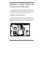
1
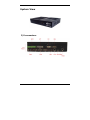
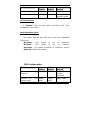
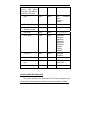
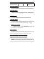
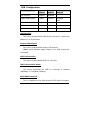
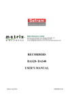
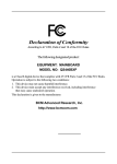
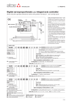
WBX-6200F Intel Pentium-M / Celeron-M Fanless Engine Box User’s Manual Version V1.1 Copyright © 2006, i-Tech Corp., ALL RIGHTS RESERVED. All other brand names are registered trademarks of their respective owners. Copyright Notice Copyright © 2006 by i-Tech Technology Corp. All Rights Reserved. Printed in Taiwan. This publication is protected by copyright and all rights are reserved. No part or whole of it may be reproduced or transmitted in any form or by any means, electronic or mechanical, including photocopying and recording without prior consent of i-Tech TECHNOLOGY CORP. The information in this document has been carefully checked and is believed to be accurate. However, i-Tech TECHNOLOGY CORP. assumes no responsibility for any errors that may appear in this document. The material contained herein is for informational purposes only. The information contained in this document is subject to change without any notices. Safety Precautions Before getting started, read the following important cautions. 1. The WBX-6200F Engine Box may not come equipped with an operating system. An operating system must be loaded first before installing any software into the computer. 2. Be sure to ground yourself to prevent static charge when installing the internal components. Use a grounding wrist strap and place all electronic components in any static-shielded devices. Most electronic components are sensitive to static electrical charge. 3. Disconnect the power from the WBX-6200F Engine Box before making any installation. Be sure both the system and the external devices are turned OFF. Sudden surge of power could ruin sensitive components. Make sure the WBX-6200F Engine Box is properly grounded. 4. Turn OFF the system power before cleaning. Clean the system using a cloth only. Do not spray any liquid cleaner directly onto the system. 5. The WBX-6200F Engine Box is not susceptible to intense shock or vibration. When assembling the WBX-6200F Engine Box, make sure it is securely installed. 6. If opening the cover for maintenance is a must, only a trained III technician is allowed to do so. Integrated circuits on computer boards are sensitive to static electricity. To avoid damaging chips from electrostatic discharge, observe the following precautions: 9 Before handling a board or integrated circuit, touch an unpainted portion of the system unit chassis for a few seconds. This will help to discharge any static electricity on your body. 9 When handling boards and components, wear a wrist-grounding strap, available from most electronic component stores. 7. Follow below instructions and notice the caution for replacing and disposing of the RTC Lithium battery CR2032 for safety consideration: CAUTION: Danger of explosion if battery is incorrectly replaced. Replace only with the same or equivalent type recommended by the manufacturer. Dispose of used batteries according to the manufacturer’s instruction. IV Acknowledgments All product names or trademarks are properties of their respective owners. V IMPORTANT NOTE: When the system boots without the CRT being connected, there will be no image on screen when you insert the CRT/VGA cable. To show the image on screen, the hotkey must be pressed (At this point, press Ctrl-Alt-F1 simultaneously, if you are using CRT monitor. If you are using LVDS LCD panel, press Ctrl-Alt-F3. If you are using DVI monitor, press Ctrl-Alt-F4.) VI Table of Contents How to Use This Manual ................................................ IX System Overview............................................................... 1 Introduction.................................................................. 1 Features....................................................................... 1 System View................................................................. 5 I/O connectors ..............................................................5 Unpacking .................................................................... 6 Getting Started.................................................................. 7 Setting Up the System ................................................... 7 Installing System Software ............................................. 8 Installing the Drivers...................................................... 9 BIOS Setup Information .................................................. 10 Entering Setup ............................................................ 10 Main Menu.................................................................. 12 Advanced Settings ....................................................... 13 CPU Configuration ....................................................... 13 IDE Configuration ........................................................ 14 Super IO Configuration................................................. 18 ACPI Configuration...................................................... 21 USB Configuration ...................................................... 22 PCIPnP Settings .......................................................... 23 Boot Settings .............................................................. 25 Security Settings ......................................................... 29 Chipset Settings .......................................................... 30 Power Settings ............................................................ 34 Exit Options ................................................................ 38 VII POST Code Checkpoints................................................ 39 AMIBIOS Beep Codes ................................................... 40 Flash BIOS Utility ........................................................ 40 Appendix A. Jumper Setting and Connectors List ............ 42 Appendix B. System Assembly Reference ........................ 56 Appendix C. Watchdog Timer Configuration .................... 57 Appendix D. Digital I/O Sample Code.............................. 59 VIII How to Use This Manual This manual is written for the system integrator, PC technician and knowledgeable PC end user. It describes how to configure your WBX-6200F Engine Box to meet various operating requirements. The user’s manual is divided into three chapters, with each chapter addressing a basic concept and operation of the server board. Chapter 1: System Overview - presents what you have inside the box and gives you an overview of the product specifications and basic system architecture for the WBX-6200F Engine Box. Chapter 2: System Installation - describes how to set up the system. Chapter 3: BIOS Setup Information - specifies the meaning of each setup parameter, how to get advanced BIOS performance and update to a new BIOS. Additionally, the POST checkpoint list will give you a guide for troubleshooting. The contents of this manual are subject to change without prior notice. These changes will be incorporated in new editions of this manual. i-Tech may make supplements or changes for the product described in this manual at any time. IX System Overview Introduction WBX-6200F Engine Box series are based-on the features of high performance for Pentium-M or Celeron-M platform with low power consumption. WBX-6200F Engine Box is mainly designed for industrial automation or digital signage solution with slim and true fanless feature. With GPIO connector for data collection and device control, and storage can support internal DOM and external Compact Flash memory card, or one 2.5” HDD. Features The WBX-6200F Engine Box features: CPU Intel Pentium-M / Celeron-M 1.8GHz with socket System Memory DDR 266/333 SODIMM x 1 (without ECC) Mass Storage Device Internal 2.5” HDD drive bay with anti-vibration kit IDE interface UDMA 100 IDE interface x 2 CF interface 1 x bootable Compact Flash slot (onboard) for CF type I/II storages 1 PCMCIA interface One PCI card-bus interface for Complies with PC Card 95/97/98, Card-32(32 bit), PCMCIA V2.1/JEIDA 4.2(16 bit), supports type I/II (PCMCIA and CF cannot be used simultaneously) Mini-PCI interface 1 x 32-bit Mini-PCI socket (support 802.11b/g and DVB modules) Audio Function Realtek ALC202 AC97 Audio Codec, interface with Line-in, Line-out and Microphone-in ports Ethernet Function ICH4 + 86562ET PHY 10/100 Base-T Ethernet with external RJ-45 connector, WOL/PXE function BIOS AMI BIOS, 4 MB Flash EEPROM, Plug-and-Play compatible Watchdog Function 1~255 minutes, software programmable 2 System Specification NOTE: Specifications are subject to change without notice. Parts System Board CPU Specifications Intel Pentium-M / Celeron-M 1.8GHz with socket System memory DDR 266/333 SODIMM x 1 (without ECC) I/O interfaces - VGA port x 1 / DVI x 1 - Serial port (RS-232 x 2, RS-232 /422/485 x 1) - PS/2 keyboard/mouse port - Parallel port x 1 - GPIO: 4-bit input, 4-bit output - LAN RJ-45 x 1 - PCMCIA or simultaneously) USB and Audio CF x 1 (not - USB 2.0 port x 4 - Microphone input connector - Line input connector - Line output connector Storage device Hard drive disk Internal 2.5” HDD drive bay with anti-vibration kit AC-to-DC Power Adapter Output power Max. 80 Watt Input voltage AC 100 ~ 240V / 47 ~ 63 Hz, 1.9A Output voltage DC12V @ 6.66A Dimension 292 x 200 x 66 mm (L x W x H) Weight 3.2 kg 3 Environment Temperature Operating: 0 °C ∼ 40 °C Storage: –20 °C ∼ 60 °C Humidity 4 10% ∼ 90% @ RH, non-condensing System View I/O connectors 5 Unpacking After unpacking the shipping carton, you should find these standard items: The WBX-6200F Engine Box Accessory box including the followings: – – – – – – – AC adapter x 1 AC power cord x 1 40-pin 2.54 mm pitch IDE cable x 1 Y cable for PS2 keyboard and mouse x 1 4-pin IDE device power cable x 1 Mounting bracket x 2, M3L6 screw x 8 CD-ROM for drivers, utility, Quick installation Guide and user manual Inspect all the items. If any item is damaged or missing, notify your dealer immediately. 6 Getting Started This chapter tells you how to set up the system. Setting Up the System The following is a summary of the steps in setting up the system for use. CAUTION: Make sure that power to the system and each of the devices to be connected is switched OFF before plugging in the connectors. 1. Make any required external connections such as the keyboard, and mouse. 2. Plug the appropriate end of the power cord into the power connector of the system. Then plug the other end of the power cord to an electrical outlet. 3. Press the power switch of the system to turn on the system’s power. 4. If necessary, run the BIOS SETUP program to configure the system (see Chapter 3). 5. Install the software drivers if necessary. 7 Installing System Software Recent releases of operating systems from major vendors include setup programs, which load automatically and guide you through hard disk preparation and operating system installation. The guidelines below will help you determine the steps necessary to install your operating system on the Engine Box hard drive. NOTE: Some distributors and system integrators may have already pre-installed system software prior to shipment of your Engine Box. Installing software requires an installed HDD. Software can be loaded in the WBX-6200F Engine Box using any of below methods: 1. Method 1: Use the Ethernet You can use the Ethernet port to download software from the net to the HDD that has been pre-installed in WBX-6200F Engine Box. 2. Method 2: Use the COM Port By connecting another PC to the WBX-6200F Engine Box with an appropriate cable, you can use transmission software to transmit Operation System Software to the HDD that has been pre-installed in the WBX-6200F Engine Box. 3. Method 3: Use a External CD-ROM You can use the external CD-ROM to transmit the software to the HDD that has been pre-installed in the WBX-6200F Engine Box. 8 Installing the Drivers After installing your system software, you will be able to set up the LAN, VGA, Audio and USB functions. All drivers are stored in a CD disc, which can be found in your accessory pack. The various drivers and utilities in the disc have their own text files that help users install the drivers and understand their functions. 9 BIOS Setup Information WBX-6200F is equipped with the AMI BIOS stored in Flash ROM. This BIOS has a built-in Setup program that allows users to modify the basic system configuration easily. This type of information is stored in CMOS RAM so that it is retained during power-off periods. When system is turned on, WBX-6200F communicates with peripheral devices and checks its hardware resources against the configuration information stored in the CMOS memory. If any error is detected, or the CMOS parameters need to be initially defined, the diagnostic program will prompt the user to enter the SETUP program. Some errors are significant enough to abort the start-up. Entering Setup Turn on or reboot the computer. When the message “Hit <DEL> if you want to run SETUP” appears, press <Del> key immediately to enter BIOS setup program. If the message disappears before you respond, but you still wish to enter Setup, please restart the system to try “COLD START” again by turning it OFF and then ON, or touch the "RESET" button. You may also restart from “WARM START” by pressing <Ctrl>, <Alt>, and <Delete> keys simultaneously. If you do not press the keys at the right time and the system will not boot, an error message will be displayed and you will again be asked to, Press <F1> to Run SETUP or Resume 10 In BIOS setup, you can use the keyboard to choose among options or modify the system parameters to match the options with your system. The table below will show you all of keystroke functions in BIOS setup. Keys to navigate within setup menu Key Up Arrow Down Arrow Left Arrow Right Arrow Enter Key Tab key + key - key Esc key F1 key F10 key 11 Functions Move to the previous item Move to the next item Move to the item on the left (menu bar) Move to the item on the right (menu bar) Go to Sub Screen Select field Increase the numeric value or make changes Decrease the numeric value or make changes Main Menu -- Quit and not save changes into CMOS Status Page Setup Menu and Option Page Setup Menu -- Exit current page and return to Main Menu General help on Setup navigation keys Save all the CMOS changes and exit Main Menu Once you enter WBX-6200F AMI BIOS CMOS Setup Utility, you should start with the Main Menu. The Main Menu allows you to select from seven setup functions and one exit choice. Use left/right arrow keys to switch among setup menus or use up/down arrow keys to move among bios options in the menu. NOTE: It is strongly recommended to reload Optimal Setting if CMOS is lost or BIOS is updated. Main Menu Item Description AMIBIOS Version AMIBIOS (Display Only) version number BIOS Build Date AMIBIOS (Display Only) build date BIOS ID AMIBIOS identification (Display Only) Processor Type Processor Manufacturer (Display Only) Processor Speed The speed (Display Only) Processor Count Number of (Display Only) System Memory Size Amount of (Display Only) of Physical systm System Time Change the system time System Date Change the system date 12 number Information processor Processors memory Advanced Settings This setup reference table includes all the Optimal, Failsafe, and Other options setting in each BIOS setup item. It is very easy to cross reference. If you want to go details, you can directly refer to item description in sub-section. There are six submenus in this menu: CPU Configuration, IDE configuration, Super IO configuration, Hardware Health Configuration, ACPI Configuration and USB Configuraton. CPU Configuration BIOS Items Description Module Version (Display Only) Manufacturer Manufacturer (Display Only) Brand String the hard coded text string the is contained in the processor. (Display Only) Frequency the operating (Display Only) FSB Speed the front side bus speed of the processor. (Display Only) Cache L1 The level one cache that is reported by the processor. (Display Only) Cache L2 The level two cache that is reported by the processor. (Display Only) 13 of frequency the of the processor processor. BIOS Setup Items Optimal Default Failsafe Default Other Options/ Remark CPU TM function Disabled Enabled Disabled Intel SpeedStep Tech. Automatic Disabled Maximun Speed Minimun Speed CPU TM function If 'Enabled', CPU will slow down to 600Mhz when CPU's temperature rise to 80oC. Intel SpeedStep Tech. This option specifies how CPU works with Intel SpeedStep Technology. 'Maximum': CPU speed is set to maximum. 'Minimum': CPU speed is set to minimun. 'Automatic': CPU speed controlled by Operation system. 'Disabled': Default CPU speed. IDE Configuration BIOS Setup Items Optimal Default Failsafe Default Other Options/ Remark OnBoard Controller PCI IDE Both Both Disabled Primary Secondary OnBoard PCI Operate Mode IDE Legacy Mode Lagacy Mode Native Mode 14 - - [Submenu] Type Auto Auto Not Installed Auto CD/DVD ARMD LBA/Large Mode Auto Auto Disabled Block (Multi-Sector Transfer) Mode Auto Auto Disabled PIO Mode Auto Auto 0, 1, 2, 3, 4 DMA Mode Auto Auto SWDMA0 SWDMA1 SWDMA2 MWDMA0 MWDMA1 MWDMA2 UDMA0 UDMA1 UDMA2 S.M.A.R.T. Auto Auto Disabled Enabled 32Bit Data Transfer Enabled Disabled - ARMD Type Auto Auto Floppy, Hard Disk Disabled Disabled Enabled Primary IDE Master Primary IDE Slave Secondary IDE Master Seconday IDE Slave Emulation Hard Disk Write Protect OnBoard PCI IDE Controller This option specifies the onboard IDE controller channels that will be used. The settings are Disabled, Primary, Secondary, or Both. 15 OnBoard PCI IDE Operate Mode Notice!! Native Mode ONLY for Windows XP and 2000. Primary IDE Master Primary IDE Slave Secondary IDE Master Secondary IDE Slave System will auto-detect all available IDE devices. Devices can be configured in sub-menu by pressing 'Enter' key Type This option sets the type of device that the AMIBIOS attempts to boot from after the Power-On Self-Test (POST) has completed. 16 Option Description Not Installed Set this value to prevent the BIOS from searching for an IDE disk drive on the specified channel Auto Set this value to allow the BIOS auto detect the IDE disk drive type attached to the specified channel. This setting should be used if an IDE hard disk drive is attached to the specified channel. This is the default setting. CD/DVD This option specifies that an IDE CD-ROM drive is attached to the specified IDE channel. The BIOS will not attempt to search for other types of IDE disk drives on the specified channel. ARMD This option specifies an ATAPI Removable Media Device. This includes, but is not limited to: ZIP, LS-120 LBA/Large Mode LBA (Logical Block Addressing) is a method of addressing data on a disk drive. In LBA mode, the maximum drive capacity is 137 GB. Block (Multi-Sector Transfer) Mode This option sets the block mode multi sector transfers option. PIO Mode IDE PIO (Programmable I/O) mode programs timing cycles between the IDE drive andthe programmable IDE controller. As the PIO mode increases, the cycle time decreases. DMA Mode This setting allows you to adjust the DMA mode options. The Optimal and Fail-Safe S.M.A.R.T. 17 Self-Monitoring Analysis and Reporting Technology (SMART) feature can help predict impending drive failures. 32Bit Data Transfer This option sets the 32-bit data transfer option. ARMD Emulation Type ATAPI Removable Media Device (ARMD) is a device that uses removable media, such as the LS120, MO (Magneto-Optical), or Iomega Zip drives. If you want to boot up from media on an ARMD, it is required that you emulate boot up from a floppy or hard disk drive. This is especially necessary when trying to boot to DOS. You can select the type of emulation used if you are booting from such a device. This option only appears when an ARMD device is installed. Hard Disk Write Protect Default value is 'Disabled'. If 'Enabled', it will prevent you from making any changes to the hard disk drive. Essentially, the hard disk drive acts as a CD-ROM disc would. Super IO Configuration BIOS Setup Items 18 Optimal Failsafe Other Options/ Default Default Remark 378 Disabled 278, 3BC Parallel Port Mode Normal Normal Bi-Directional ECP EPP ECP & EPP Parallel Port IRQ IRQ7 IRQ7 IRQ5 Disabled Disabled Specific Any Key - Enter Password Parallel Port Address Keyboard PowerOn Specific Key PowerOn - Key Mouse PowerOn Disabled Disabled Left Button Right Button Serial Port1 Address 3F8 3F8 Disabled, 3F8, 3E8, 2F0, 2E0 Serial Port1 IRQ Serial Port2 Address Serial Port2 IRQ Serial Port3 Address Serial Port3 IRQ Serial Port4 Address 19 4 4 4, 9, 10, 11 2F8 2F8 Disabled, 3F8, 3E8, 2F0, 2E0 3 3 3, 9, 10, 11 2F0 2F0 Disabled, 3F8, 3E8, 2F0, 2E0 2F8, 2E8 2F8, 2E8 2F8, 2E8 11 11 4, 5, 6, 7, 9, 10, 11, 12 2E0 2E0 Disabled, 3F8, 3E8, 2F0, 2E0 2F8, 2E8 Serial Port4 IRQ 10 10 (reserved for touchscreen) 3, 5, 6, 7, 9, 10, 11, 12 Parallel Port Address This option specifies the I/O address used by the parallel port. Parallel Port Mode This option specifies the parallel port mode. Available options are: Normal, Bi-Directional, EPP, ECP. Parallel Port IRQ This option specifies the IRQ used by the parallel port. Keyboard PowerOn This option specifies how the system can be turned on by using the keyboard. Options are 'Disabled', 'Specific key', 'Any key'. Specific Key PowerOn If Keyboard PowerOn is set to 'Specific key', here you can set password to initiate poweron. Mouse PowerOn This option specifies how the system can be turned on by using the mouse. Options are Disabled, Left button, Right button. Serial Port1 Address, Serial Port2 Address, Serial Port3 Address, Serial Port4 Address This option specifies the base I/O port address of serial ports. Notice!! Serial Port4(COM4) is reserved for touchscreen Controller. 20 Serial Port4 option will not shown in Models without touchscreen Serial Port1 IRQ, Serial Port2 IRQ Serial Port3 IRQ, Serial Port4 IRQ This option specifies the IRQ of serial ports. ACPI Configuration BIOS Setup Items Optimal Default Failsafe Default Other Options/ Remark General ACPI Configuration - - [Submenu] S1 (POS) S1 (POS) S3 Auto - - [Submenu] APCI ACPI SCI IRQ Disabled Disabled Enabled USB Device Wakeup From S3 Disabled Disabled Enabled Suspend Mode Chipset ACPI Configuration (STR) Suspend Mode This option allows you to configure Suspend Mode settings. APIC ACPI SCI IRQ This option enable/disable the APIC ACPI SCI IRQ. USB Device Wakeup From S3 This option enable/disable USB device wakeup from s3. 21 USB Configuration BIOS Setup Items Optimal Default Failsafe Default Other Options/ Remark USB Function Enabled Disabled - Legacy USB Support Enabld Enabled Disabled Auto USB 2.0 Controller Enabled Disabled - USB 2.0 Controller Mode HiSpeed FullSpeed - BIOS EHCI Hand-Off Enabled Enabled Disabled USB Function This option enable/disable USB device controllers, system can address up to 6 USB ports. Legacy USB Support This option enable/disable legacy USB support. 'Auto' option disables legacy support if no USB devices are connected. USB 2.0 Controller This option enable/disable USB 2.0 controller. USB 2.0 Controller Mode This option configures the USB 2.0 controller in HiSpeed (480Mbps) or FullSpeed (12Mbps). BIOS EHCI Hand-Off This is a walkaround for OSes without EHCI hand-off support. 22 The EHCI ownership change should claim by EHCI driver. PCIPnP Settings PCI/Pnp Settings BIOS Setup Items Optimal Default Failsafe Default Other Options/ Remark Clear NVRAM No No Yes Plug & Play O/S No No Yes PCI Latency Timer 64 64 32, 64, 96, 128, 160, 192, 224, 248 Allocate IRQ to PCI VGA Yes Yes No PCI IDE BusMaster Disabled Disabled Enabled Clear NVRAM This option is used to clear NVRAM and check or update ESCD (Extended System Configuration Data) data after system power on. Plug & Play O/S Default value is 'No', This allows the BIOS to configure the devices in the system. If 'Yes', this value allows the operating system to configure all Plug and Play devices not required during boot. Use this setting if your operating system supports plug and play devices. PCI Latency Timer 23 This option allows the PCI Latency Timer to be adjusted. Basically, it allows you to set a delay to allow the BIOS to find all PCI devices. This option sets the latency of all PCI devices on the PCI bus. The settings are in units equal to PCI clocks. Allocate IRQ to PCI VGA This option allows the system to adjust the Allocate IRQ to VGA setting. If 'Yes', System will assigns IRQ to PCI VGA card if card requests IRQ. If 'No', System does not assign IRQ to PCI VGA card even if card requests an IRQ. PCI IDE BusMaster This option enable/disable PCI busmastering for reading / writing to IDE drives. 24 Boot Settings Boot Settings BIOS Setup Items Optimal Default Failsafe Default Other Options/ Remark Boot Settings Configuration - - [Submenu] Configure Settings during System Boot Quick Boot Enabled Enabled Disabled Quiet Boot Disabled Disabled Enabled AddOn ROM Display Mode Force BIOS Force BIOS Keep Current Bootup Num-Lock On On Off Auto Auto Disabled Enabled Wait For 'F1' If Error Enabled Enabled Disabled Hit 'DEL' Message Display Enabled Enabled Disabled Interrupt 19 Capture Disabled Disabled Enabled - - [Submenu] Specifies the Boot Device Priority sequence - - Options are varied by actual Devices Configuraton. - - [Submenu] Specifies the Boot PS/2 Support Mouse Boot Device Priority 1st Boot Device 2nd Boot Device --12th Boot Device Hard Disk Drives 25 Device Priority sequence from available Hard Drives 1st 2nd --12th Drive Drive Drive - - Options are varied by actual Devices Configuraton. Boot Setting Configuration Quick Boot This option enable/disable quick boot mode. If 'Enabled', this will allow BIOS to skip certain tests while booting. This will decrease the time needed to boot the system. Quiet Boot This option enable/disable quiet boot mode. If 'Enabled', this will display OEM Logo instead of POST messages. If 'Disabled', this will display normal POSt messages. AddOn ROM Display Mode This option sets display mode for option ROM. If "Force BIOS", this value displays the option ROM even if the option ROM is set to not display during boot. If "Keep Current", this value allows the option ROM to determine whether or not it is displayed. Bootup Num-Lock 26 This option turns on/off Num-lock at boot. PS/2 Mouse Support This option turns on/off PS/2 mouse support at the BIOS level. Default value is 'Auto', this value allows the BIOS to determine if a PS/2 mouse is being used.. Wait For 'F1' If Error This option specifies how system act if error occurs at boot. If 'Enabled', this value allows the system to halt on errors while it waits for you to press the <F1> key if the BIOS detects an error during POST. If 'Disabled', this value prevents the system from waiting for you to press the <F1> key if the BIOS detects an error during POST. Hit 'DEL' Message Display This option turns on/off the "Press DEL to run Setup" message in POST. Interrupt 19 Capture This option enable/disable option ROMS to trap interrupt 19. Boot Device Priority Specifies the Boot Device Priority sequence in sub-menu. 27 1st Boot Device, 2nd Boot Device, ... , 12th Boot Device Set the boot device options to determine the sequence in which the computer checks which device to boot from. Hard Disk Drives 1st Drive, 2nd Drive, ... , 12th Drive Specifies the Boot Device Priority sequence from available Hard Drives. 28 Security Settings Security Settings BIOS Setup Items Optimal Default Failsafe Default Other Options/ Remark Change Password - - Enter Password Change User Password - - Enter Password Boot Sector Protection Disabled Disabled Enabled Supervisor Virus Change Supervisor Password Install or change the password. Change User Password Install or change the password. Boot Sector Virus Protection This option enable/disable Boot Sector Virus Protection. 29 Chipset Settings Chipset Settings BIOS Setup Items Optimal Default Failsafe Default Other Options/ Remark NorthBridge Configuration - - [Submenu] Optoins for NB DRAM Frequency Auto 200 Mhz 200 266 333 Auto Configure DRAM Timing by SPD Enabled Enabled Disabled Memory Hole Disabled Disabled 15MB-16MB Internal Graphics Mode Select Enabled, 16MB Enabled, 8MB Disabled Enabled, 1MB Enabled, 4MB Enabled, 8MB Enabled, 16MB Enabled, 32MB Graphics Size 64MB 64MB 64MB, 256MB CRT+DVI - CRT, DVI - - [Submenu] Options for SB Auto Auto Disabled Enabled Disabled - Power Off Power Off Power Power Aperture Boot Display Device SouthBridge Configuration OnBoard Audio AC'97 OnBoard LAN Restore on AC Power Loss 30 Mhz Mhz Mhz 128MB, Off On Last State Northbridge Configuration DRAM Frequency The value represents the performance parameters of the installed memory chips (DRAM). Do not change the value from the factory setting unless you install new memory that has a different performance rating. Configure DRAM Timing by SPD SPD (Serial Presence Detect) is located on the memory module. The BIOS can read information coded in SPD during system boot up. Memory Hole Default value is 'Disabled'. This value prevents a memory hole being reserved in system memory between 15 MB – 16 MB for ISA adapter ROMs. If '15 MB-16 MB', this value reserves the area of system memory between 15 MB – 16 MB for ISA adapter ROMs. When this area is reserved, it cannot be cached. Internal Graphics Mode Select This option specifies the amount of system memory used by the Internal graphics device. Graphic Aperture Size 31 Memory mapped and graphics data structures can reside in a Graphics Aperture. This area is similar to a buffer. The BIOS will automatically report the starting address of this buffer to the operating system. Boot Display Device This option specifies the boot display device. Southbridge Configuration OnBoard AC'97 Audio This option enable/disable OnBoard AC'97 Audio controller. OnBoard Lan This option enable/disable ICH4 OnBoard LAN controller. Restore on AC Power Loss This function allows you to set whether or not to restart the system after power interruptions. Default values is 'Power Off', use this value if you want the system to always power off after a power interruption. If 'Power On', use this value if you want the system to always power on after a power interruption If 'Last State', Use this value if you want the system to power on if the system was on before a power interruption. If the system was not on, it will stay off when power is restored. 32 33 Power Settings Power Settings BIOS Setup Items Optimal Default Failsafe Default Other Options/ Remark Power APM Enabled Enabled Disabled Video Power Down Mode Suspend Disabled Disabled Standby Suspend Hard Disk Power Down Mode Suspend Disabled Disabled Standby Suspend Standby Time Out Disabled Disabled Disabled, 1 2 Min, 4 8 Min, 10 20 Min, 30 40 Min, 50 60 Min Min, Min, Min, Min, Min, Suspend Time Out Disabled Disabled Disabled, 1 2 Min, 4 8 Min, 10 20 Min, 30 40 Min, 50 60 Min Min, Min, Min, Min, Min, Keyboard & PS/2 Mouse MONITOR MONITOR IGNORE FDC/LPT/COM Ports MONITOR MONITOR IGNORE Primary master IDE MONITOR MONITOR IGNORE Primary slave IDE MONITOR MONITOR IGNORE Secondary master IDE MONITOR MONITOR IGNORE Secondary slave IDE MONITOR MONITOR IGNORE 34 Management/ CPU Thermal Enabled Disabled Enabled Thermal Active Temperature 90oC/194oF 90oC/194oF 60oC/140oF 65oC/149oF 70oC/158oF 75oC/167oF 80oC/176oF 85oC/185oF 90oC/194oF Thermal Slow Clock Ratio 50% 50% 87.5% 75.0% 62.5% 50% 37.5% 25% 12.5% Power Button Mode On/Off On/Off Suspend Resume On Ring Disabled Disabled Enabled Resume On PME# Disabled Disabled Enabled Disabled Disabled Enabled RTC Alarm Date (Days) 15 15 Every 01-31 System Time 12:30:30 12:30:30 Enter time Resume Alarm On RTC Day, Power Management / APM This option allows Power Management/APM support. Video Power Down Mode This option specifies the power state that the video subsystem enters when the BIOS places it in a power saving state after the specified period of display inactivity has expired. 35 Hard Disk Power Down Mode This option specifies the power conserving state that the hard disk drive enters after the specified period of hard drive inactivity has expired. Standby Time Out This option specifies the length of time the system needs to be inactive before it enters standby mode. Suspend Time Out This option specifies the length of time the system needs to be inactive before it enters suspend mode. Keyboard & FDC/LPT/COM Primary Primary Secondary Secondary slave IDE PS/2 master slave master Mouse Ports IDE IDE IDE If 'Monitor', this value allows the MB to wake up when one of the device selected is used. If 'Ignore', this value prevents the MB from waking up when the selected device is used. System Thermal This option enable/disable an out-of-threshold thermal reading to generate a power management event. Thermal Active Temperature 36 A temperature reading higher than specified temperature will generate a power management event. The CPU clock will throttle back a certain percentage as dictated by the value in the Thermal Slow Clock Ratio field. Thermal Slow Clock Ratio This option allows the Thermal Throttle Ratio to be selected. This type of throttling is used to lower power consumption and reduce thermals. Power Button Mode This option specifies how the power button mounted externally on the computer chassis is used. If 'On/Off', pushing the power button turns the computer on or off. If 'Suspend', Pushing the power button places the computer in Suspend mode or FullOn power mode. Resume On Ring This option enable/disable RING to generate a wake event. Resume On PME# This option enable/disable PME to generate a wake event. Resume On RTC Alarm This option enable/disable RTC to generate a wake event. RTC Alarm Date (Days) Choose 'Everyday' or '01'...'31' to specify the RTC Alarm Date. System Time 37 Choose the wakeup time for the RTC Alarm. Exit Options Exit Options BIOS Setup Items Save Changes (F10) Discard (ESC) Changes Discard (F7) Load (F9) 38 Optimal Description Exit Exit System setup after saving the changes. Exit Exit system setup without saving any changes. Changes Discards changes done so far to any of the setup questions Defaults Load Optimal Default values for all the setup questions and and POST Code Checkpoints Code E0h E1h E2h E3h E4h E5h E6h E7h E8h E9h EAh EDh EEh EFh F0h F1h F2h F3h F4h F5h FBh 39 Description Verify the Boot Block BIOS checksum. Disable the internal cache, DMA, and interrupt controllers. Initialize the system timer. Start memory refresh. Initialize the chipset registers. Set the BIOS size to 128K. Make the 512 KB base memory available. Test the base 64 KB of system memory. Send the BAT command to the keyboard controller. Make sure that <Ctrl> <Home> was pressed. Verify the main system BIOS checksum. The main system BIOS is good. Transfer control to the main system BIOS. Start the memory test. The memory test is over. Initialize the interrupt vector table. Initialize the DMA and interrupt controllers. Determine the CPU internal clock frequency. Initialize the I/O chipset, if any. Program the CPU clock-dependent chip set parameters. Enable the timer and the floppy diskette interrupt. Enable the internal cache. Copy the boot block BIOS and pass control to the boot block BIOS in the 0000h segment. Initialize the floppy drive. Look for a diskette in drive A:. Read the first sector of the diskette. Floppy read error. Search for S876P.ROM in the root directory of the floppy diskette in drive A:. The S876P.ROM file is not in the root directory. Read the FAT table. Analyze the FAT to find the clusters occupied by the S876P.ROM. Start reading the S876P.ROM file, cluster by cluster. The S876P.ROM file is not the correct size. Disable the internal cache. Raise the Vpp. Enable Flash write and reset the Flash ROM. Detect the flash type. FCh FDh FEh FFh Start erasing flash blocks. Program the Flash ROM in the E0000-EFFFFh region. Start programming Flash at F0000-FFFFF region. Flash programming is successful. The system reboots. AMIBIOS Beep Codes Number Beeps 1 2 3 4 5 6 7 8 9 10 11 of Error Type Memory refresh timer error Parity error in base memory (first 64K block) Base memory read/write test error Motherboard timer not operational Processor error 8042 Gate A20 test error (cannot switch to protected mode) General exception error (processor exception interrupt error) Display memory error (system video adapter) AMIBIOS ROM checksum error CMOS shutdown register read/write error Cache memory test failed Flash BIOS Utility Utilize AMI Flash BIOS programming utility to update on-board BIOS for the future new BIOS version. Please contact your technical window to get this utility if necessary. NOTE: Remark or delete any installed Memory Management Utility (such as HIMEM.SYS, EMM386.EXE, 40 QEMM.EXE, …, etc.) in the CONFIG.SYS files before running Flash programming utility. 41 Appendix A. Jumper Setting and Connectors List of CPU Board This appendix gives the definitions and shows the positions of jumpers, headers and connectors. All of the configuration jumpers on WBX-6200F Engine Box are in the proper position. The default settings shipped from factory are marked with (default). Jumpers Location and list In general, jumpers on the single board computer are used to select options for certain features. To select any option, cover the jumper cap over (SHORT) or remove (NC) it from the jumper pins according to the following instructions. Here NC stands for “Not Connect”. 42 Jumper List CONNECTOR FUNCTION JP1 COM2 Function Selection JP3 Panel Power Selection JP4 CMOS Clear JP5 Backlight level REMARK Jumper Setting JP1 –COM2 Function Selection Description RS-232 RS-422 RS-485 Jumper Setting 5-6, 9-11, 10-12, 15-17, 16-18 3-4, 7-9, 13-15, 14-16, 21-22 1-2, 7-9, 8-10, 19-20 JP3 – Panel Power Selection Description Jumper Setting +3.3V 1-2 +5V 2-3 JP4 – CMOS Clear Description Jumper Setting Normal 1-2 CMOS Clear 2-3 43 JP5 – Backlight level Setting 1-2 3-4 5-6 Description +5V + 3.3 V (15”) 0V (17’) Connector Definitions Connectors Location CAUTION: When 44 connecting the power connector to the motherboard, make sure that the system is not connected to an electrical outlet. When connecting a signal cable (also called ribbon cable), Pin 1 of the cable should be aligned with Pin 1 of the connector on the motherboard. Pin 1 side of the cable is identified by a color, usually red, stripe. Pin 1 of the motherboard connector is identified by the number 1 imprinted or an additional shading on the board. 45 Connectors List The connectors on the PCBA of WBX-6200F Engine Box are used to connect external devices such as hard disk drives, printers, keyboard, serial ports, etc. Specifically, the PCBA of WBX-6200F Engine Box has the following connectors: CONNECTOR PJ1 J1 J2 J3 J4 J5 J6 J7 J8 J9 J10 J11 J12 J13 J14 J15 J17 J18 J19 J20 J21 J22 J23 J24 J26 J27 J28 J29 J30 46 FUNCTION REMARK Power Jack Connector Reset Button Audio Jack KB/MS Connector COM1 COM2 COM3 Ethernet Port COM4 Parallel Port USB Port USB Port IrDA (SIR + CIR) GPIO Interface DVI Interface Internal USB Power Button Interface CRT Interface Standard 44 Pin IDE Connector Standard 40 Pin IDE Connector Passive Speaker Connector Passive Speaker Connector HDD Power Connector Power/HDD Indicator Standard Mini-PCI Interface Standard Compact Flash (IDE) Connector (Bootable) Standard PCMCIA/Card Bus Connector Panel Backlight Brightness Control Panel Backlight Brightness Control CONNECTOR J31 J33 J34 J35 J500 FUNCTION Fan Connector LVDS Interface Standard +5V PCI Slot Fan Connector LVDS Interface PJ1 – Power Jack Connector Pin 1 2 3 4 5 Signal Description Ground DC In (+12V~+24V) Ground DC In (+12V~+24V) Ground J1 – Reset Button J2 – Audio Jack Pin 1 2 3 Signal Description Line Out (stereo) Line In (stereo) Microphone (mono) J3 – KB/MS Connector Pin 1 2 3 4 5 6 47 Signal Description KB data MS data Ground +5V KB clock MS clock REMARK J4, J6 – COM1, COM3 Pin 1 2 3 4 5 6 7 8 9 Signal Description Carrier Detect Receive Data Transmit Data Data Terminal Ready Ground Data Set Ready Request to Send Clear to Send Ring Indicator J5 – COM2 Pin 1 2 3 4 5 6 7 8 9 48 Signal Description RS-232 RS-422 Carrier Transmit Detect Data Receive Transmit Data Data + Transmit Receive Data Data + Data Receive Terminal Data Ready Ground NC Data Set NC Ready Request NC to Send Clear to NC Send Ring NC RS-485 Transmit Data Transmit Data + NC NC NC NC NC NC NC Indicator J7 – Ethernet Port Pin 1 2 3 4 5 6 7 8 LED1 LED2 Signal Description Transmit Data+ Transmit DataReceive Data+ NC NC Receive DataNC NC LINK/ACTIVE LED SPEED LED J8 – COM4 Pin Pin 1 Signal Description Carrier Detect 3 Receive Data 4 5 Transmit Data 6 7 Data Terminal Ready 8 9 Ground 10 +5V Pin Signal 2 Signal Description Data Set Ready Request to Send Clear to Send Ring Indicator J9 – Parallel Port Pin 49 Signal 1 3 5 7 9 11 13 15 17 19 21 23 25 Description Strobe Data Bit 0 Data Bit 1 Data Bit 2 Data Bit 3 Data Bit 4 Data Bit 5 Data Bit 6 Data Bit 7 Acknowledge Busy Paper End Select 2 4 6 8 10 Description Auto feed Error Initialize Select In Ground Ground Ground Ground Ground Ground Ground Ground NC J10, J11 – USB Port Pin 1 2 3 4 Signal Description +5V Data Data + Ground J12 – IrDA (SIR + CIR) Pin 1 3 5 7 9 50 Signal Description +5V NC IR data receive Ground IR data Pin 6 Signal Description NC Consumer IR data receive +5VSB 8 10 NC NC 2 4 transmit J13 – GPIO Interface Pin Signal Description GPO 1 GPO 2 GPO 3 GPO 4 GPO 5 GPO 6 GPO 7 GPO 8 +5V Ground 1 3 5 7 9 11 13 15 17 19 Pin Signal Description GPI 1 GPI 2 GPI 3 GPI 4 GPI 5 GPI 6 GPI 7 GPI 8 +5V Ground 2 4 6 8 10 12 14 16 18 20 Pin head on Chassis 1 2 3 4 5 6 7 8 9 10 +5V GPO4 GPO3 GPO2 GPO1 Ground GPI4 GPI3 GPI2 GPI1 J14 – DVI Interface Pin 1 3 5 51 Signal Description TMDS Data 2TMDS Data2 shield DDC Data Pin 2 4 6 Signal Description TMDS Data 2+ DDC Clock Analog Vertical Snyc 7 8 17 TMDS Data 1TMDS Data1 shield Ground (for +5V) TMDS Data 0TMDS Data0 shield TMDS Clock - 19 21 Analog Green Analog Blue 20 22 23 Analog Ground 24 9 11 13 15 10 12 14 16 18 J15 – Internal USB Pin 1 2 3 4 Signal Description +5V Data Data + Ground J17 – Power Button Interface Pin 1 2 52 Signal Description +5V Power on TMDS 1+ +5V Data Hot Plug Detect TMDS Data 0+ TMDS Clock + TMDS Clock shield Analog Red Analog Horizontal Sync Analog Ground J18 – CRT Interface Pin 1 3 5 7 9 11 13 15 Signal Description Red Blue Ground Ground +5V NC Horizontal Sync DDC Clock Pin 2 4 6 8 10 12 14 Signal Description Green Ground Ground Ground Ground DDC Data Vertical Sync 16 NC J19 – Standard 44 Pin IDE Connector (Primary, master) J20 – Standard 40 Pin IDE Connector (Primary, slave) J21, J22 – Passive Speaker Connector J21 (Right Channel) Pin Signal Description 1 AMP. Out + 2 AMP. Out - J22 (Left Channel) Pin Signal Description 1 AMP. Out + 2 AMP Out - J23 – HDD Power Connector Pin 1 53 Signal Description +12V 2 3 4 Ground Ground +5V J24 – Power/HDD Indicator Pin 1 2 3 4 Signal Description HDD Active Indicator +5V +5V Power indicator J26 – Standard Mini-PCI Interface J27 J28 – Standard Compact Flash (IDE) Connector (Bootable, Secondary, and Master) – Standard Connector PCMCIA/Card Bus J29, J30 – Panel Backlight Brightness Control J29 Pin 54 1 Signal Description Back Light Up 2 Ground J30 Pin 1 2 Signal Description Back Light Down Ground J31, J35 – Fan Connector J31 (CPU) Pin Signal Description 1 Ground 2 Fan PWM Control 3 Fan RPM Signal J35 (System) Pin Signal Description 1 Ground 2 Fan PWM Control 3 Fan RPM signal J34 – Standard +5V PCI Slot 55 Appendix Reference 56 B. System Assembly No. 01 02 03 04 05 06 07 08 09 10 11 12 13 14 15 16 17 18 19 20 21 22 23 24 25 26 27 28 29 Statement S-Stand off Screws, M2 x 0.4P Cable, LPT Cable, GPIO Bracket, SET Screws, M3 x L6 Bracket, PCMCIA Cable, switch Cable, LED Rubber foot Housing, LED Main board VGA board Bracket, DVI Screw bushing, M3 x 0.5P Bracket, CPU heatsink Screws, MS+N, M3 x L6 Heatsink Bracket, HDD Screw washer, M3 x L8 Damper, vibration absorber Bracket, heatsink Bracket, HDD HDD Heatsink Shock absorber Screw washer, M3 x L12 Screw, 6#-32 3/16 Bracket, cover Appendix 57 C. Watchdog Qty. 12 2 1 1 2 11 1 1 1 4 2 1 1 1 4 1 5 1 1 4 4 1 1 1 1 2 11 7 1 Timer Configuration The WDT is used to generate a variety of output signals after a user programmable count. The WDT is suitable for use in the prevention of system lock-up, such as when software becomes trapped in a deadlock. Under these sort of circumstances, the timer will count to zero and the selected outputs will be driven. Under normal circumstance, the user will restart the WDT at regular intervals before the timer counts to zero. SAMPLE CODE: This code and information is provided "as is" without warranty of any kind, either expressed or implied, including but not limited to the implied warranties of merchantability and/or fitness for a particular purpose. outportb(0x4e,0x87); outportb(0x4e,0x87); //(Write twice to) enter the (chip) configuration mode outportb(0x4e,0x07); outportb(0x4f,0x08); //Enter the logic device (8) 58 outportb(0x4e,0xf6); outportb(0x4f,0xSec); // 0xSec = seconds time out. // For example: // 0x00 -> Time-out diable // 0x01 -> time-out occurs after 1 second // 0x02 -> time-out occurs after 2 seconds // 0xff -> time-out occurs after 255 seconds outportb(0x4e,0xaa); // Exit the (chip) configuration mode Appendix D. Digital I/O Sample Code SAMPLE CODE: This code and information is provided "as is" without warranty of any kind, either expressed or implied, including but not limited to the implied warranties of merchantability and/or fitness for a particular purpose. 59 [GPI sample code]: // GPI 1~4 Data = inportb(0x4b8); // Data's bit4 = GPI 1 // Data's bit5 = GPI 2 // Data's bit6 = GPI 3 // Data's bit7 = GPI 4 // GPI 5~8 Data = inportb(0x4b9); // Data's bit0 = GPI 5 // Data's bit1 = GPI 6 // Data's bit2 = GPI 7 // Data's bit3 = GPI 8 [GPO sample code]: // GPO 1~4 Data = inportb(0x48e); Data = Data & 0b11xxxx11); 60 //where 'xxxx' means GPO1~4 output logic '0' // for example: // Data = Data & 0b11101011; // means GPO1 & GPO3 ouput '0' // GPO2 & GPO4 not changed Data = Data : 0b00yyyy00; //where 'yyyy' means GPO1~4 output logic '1' // for example: // Data = Data : 0b00010100; // means GPO2 & GPO4 output '1' // GPO1 & GPO3 not changed outportb(0x48e,Data); // GPO 5~8 Data = inportb(0x4b8); Data = Data & 0b1111xxxx); //where 'xxxx' means GPO5~8 output logic '0' // for example: // Data = Data & 0b11111010; // means GPO5 & GPO7 ouput '0' // GPO6 & GPO8 not changed Data = Data : 0b0000yyyy; //where 'yyyy' means GPO5~8 output logic '1' // for example: // Data = Data : 0b00000101; 61 // means GPO6 & GPO8 output '1' // GPO5 & GPO7 not changed Outportb(0x4b8,Data); 62