Transcript
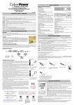
12-31-23052
Display Installation
Small flat-tip Screwdriver:
TO USER
Drill
Parking sensor
Installation & User's Manual
(
#2 Phiiiips Screwdriver
Dear User ,Thank you for choosing and using our Parking
sensor .We are going to provide the best products and the best
services to you.
""
~
Bit
Wire-8nal<e
File
Masking Tape
Black Electrical
Tape
PenciUMarker
Select an area to mount display firmly and easy for the driver to see.
Clean surface with alcohol and use the double sided tape to mount.
Control Box Installation
To insure the best performance and avoid any false
alarm or function failure, please kindly read this manual
carefully and install it accordingly.
We reserve all rights for our parking sensor ,including
Sensor Installation
the designs and the software.Any unauthorized copy or
translation is prohibited.And the products' specification and
information related in the Manual provide the references only,
and the content of the Manual will be renewed according to
the progress of the products without advance information,
and the final explaination rights of the Manual is reserved
Remove the necessary back panels to mount the control box in a safe place,
away from rain,heat or humidity.
byus.
Please note that this system is designed to be a driver's aid
and should not replace the need to drive carefully, we accept no
liability for damage or loss resulting from improper installation
or use of this product, infringement of the vehicle manufacturer's
warranty or injury or loss resulting from any accidents however
caused. If in doubt please consult aqualified auto electrician.
After installation Test
Use the following to test and verify the operation of the backup system:
Make sure that there is nothing Drilling position must be
blocking the area behind the
perpendicular to the surface
bumper, where the sensors go. of the bumper.
t
up
As you push, wiggle the sensor
and make sure it goes all the
way in and flush against the
bumper, leaving no gap.
.....§ ........§ ..... .
X
V
Install the sensors vertically;the "UP' sign must be on upside.
Warning:Do not stand behind a moving vehicle death or injury could occur.
Prior to testing, set the parking brake On, ignition key On(do not start),step
foot on brake and shiftthe vehicle into reverse. Ensure that the engine is not
running while proceeding with the following tests.
Test the system operation with a piece ofwood(60*30*lcm) or other object
(not too small) after the installation. Start with the wood more than 1m away
from the vehicle. Then move the wood closer the vehicle and ensure that the
buzzer,LED,and distance indicators display correctly.
4
'm"lt! uH,
Installation Instruction:
I. Display
3. Sensors
5. Drill bit
2. Contro lunit
4. Power Cable
6. Manual
Note:Before installing system let the components of the
exhaust system cool down. This wi1ll make the installation safer and
preclude heat damage to the backup sensor wiring or components.
Specifications
Rated voltage:DC12V
Operating range:DC9V-18V
Rated current:20mA-200mA
Display distance:O. 3-I. 8m
Ultrasonic frequency:40KHZ
Working temperature:-30·C to +80·C
5
Trouble shooting
The sensors may not work if an object does not reflect the ultrasonic waves or it has an
unusual shape, pole cardboard carton,tire of bicycle,small or slender tree,rectangular lumber
or curbs tone. The sensor may not detect another vehicle bumper if it is too high.
Also note:This system has different detection distance to the different object. To the wall,
the max detection sistance is 1.8m; tho the human body,the max detection distance is 1.0m;
to the column is 1Z40cm,the max detection distance is 1.2m.
In some special cases,the diaplay may not be the same as the real condition due to the
sensor position,obstacle shape, reflection condition and so on. Some examples are given
below
The following illustration shows the general location of the
components of the backup system.
I
Option A
If the vehicle is equipped with
high-power radio antenna.
Alarm MODE
If another vehicle bumper is too high
No buzzer or display at power up?
I. Is power wire connected to control unit correctly?
2. Verify(+)12V at control unit when vehicle is in reverse.
3. Verify the ground connection.
4. Have you connected to the correct reversing indicator wire?
5. Do you have a minimum of(+)12V and ground at the display?
False warning tone or false LED flashing
I. Is the sensor mounted too low or pointing to the ground?
Sensors do not detect any objects?
I. Is the vehicles exhaust smoking?Correct or allow it to clear before
procedding with testing.
2. Are sensors properly plugged into the correct sockets?
GUARANTEE FORM
Stamp/signature
of dealer:
Model Number
Model
LED Items
LCD buzzer
alarm Items
Awareness
DistaDee
Safe mode
130-lBOcm
Hi•••Bi...
1.3-1.8
GreeD
Alermmode
60-130cm
Di.Ri.
0.6-1.2
Yellow
Dangemode
0-60cm
Billi
0.0,0.3-0.5
Red
Safe mode
130-lBOcm
Bi ...Bi. ..
1.3-1.8
-
Sound
Digetal display
LED indicator
Safe mode
90-130=
Bi•.Bi..
90-95,1.0-1.3
-
Alermmode
60-90=
Hi.Ri.
60-90
-
Alermmode
40-60=
BIBI
40-60
-
Date of purchase
Customer's name
Telephone
Buzzer
~
Control box
Red to back-up light +12V
BlacktoGND
If there is a wire fence.
_ _<=-_,R"ed to back-up light +12V
Dangemode
0-40cm
Biiii
P
-
Safe mode
150-lBOcm
Hi.. Di••
1.5-1.B
-
Alermmode
40-1S0cm
Dangemode
0-40cm
Voice reminder
stop
40-95,1.0-1.5
-
P
-
box
~
Sensor
m;nn;m
l.Guarntee time: 12 months.
2. The guarantee will be effective with the stamp/signature
of the dealer.
3.please keep the guarantee form well to ensure 12months
guarantee.
Red to back..,p light
BlacktoGND
.• -.~
Camera
sensor
Parking sensor with rearview monitor
2
Backing up in heavy rain or snow.
Control
BlacktoGND
LCD human
Voice alarm
Items
Car registration
Number
3
If is smooth slope
If is smooth round object
6
Objects absorbing wave,e.g.Cotton
7