1
Microcontroller Systems
ELET 3232
Topic 19: Timer/Counter with PWM
Objectives
To understand the operation of an 8 bit
timer/counter in an AVR microcontroller
To understand how to use the timer/counter
to generate a PWM signal
To understand how PWM signals are used to
control servo motors
11/29/2010
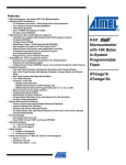
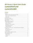
Position control
Speed control
2
Modes of Operation
Four modes of operation for Timer/Counter 0
Normal Mode:
Phase Correct PWM:
Clear Timer on Compare Match
Fast PWM:
11/29/2010
The mode we will use in PWM
CTC Mode:
we have used this mode to develop timing loops
Fast Pulse Width Modulation
3
Modes of Operation
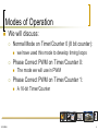
We will discuss:
Normal Mode on Timer/Counter 0 (8 bit counter):
Phase Correct PWM on Timer/Counter 0:
The mode we will use in PWM
Phase Correct PWM on Timer/Counter 1:
11/29/2010
we have used this mode to develop timing loops
A 16-bit Timer/Counter
4
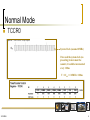
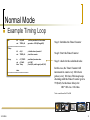
Normal Mode
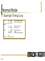
Example Timing Loop
Init:
ldi
r16,0x07
out TCCR0,r16
;============================
TDelay:
ldi
r16,0
out TCNT0,r16
; set the prescaler for the counter
; prescaler = 1024 (ATmega128)
TLoop:
; read timer/counter value
; is it $63?
; if not $63, read it again (until $63)
in
r17,TCNT0
cpi r17,0x63
brne Tloop
; initialize timer/counter 0
; starts the counter
done
;=================================
11/29/2010
5
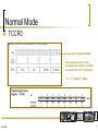
Normal Mode
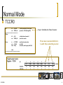
TCCR0
Init:
ldi
r16,0x07
out TCCR0,r16
;============================
TDelay:
ldi
r16,0
out TCNT0,r16
; set the prescaler for the counter
; prescaler = 1024 (ATmega128)
TLoop:
; read timer/counter value
; is it $63?
; if not $63, read it again (until $63)
in
r17,TCNT0
cpi r17,0x63
brne Tloop
Step 1: Initialize the Timer/Counter
; initialize timer/counter 0
; starts the counter
We are most concerned with bits 2,
1, and 0. They control the prescaler
done
;=================================
11/29/2010
6
Normal Mode
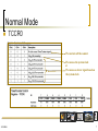
TCCR0
We can turn off the counter
We can use the system clock
or
We can use a slower signal based on
the system clock
11/29/2010
7
Normal Mode
TCCR0
System Clock (assume 10MHz)
If we used the system clock (no
prescaling) to increment the
counter, it would be incremented
every 100ns
T = 1/fclk = 1/10MHz = 100ns
11/29/2010
8
Normal Mode
TCCR0
System Clock (assume 10MHz)
If we used a prescaler of 8 to
increment the counter, it would be
incremented every 8th clock pulse
Tclk * 8 = 100ns*8 = 800ns
11/29/2010
9
Normal Mode
TCCR0
System Clock (assume 10MHz)
If we used a prescaler of 1024 to
increment the counter, it would be
incremented every 1024th clock pulse
Tclk * 1024 = 100ns*1024 = 102.4us
11/29/2010
10
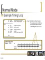
Normal Mode
Example Timing Loop
Init:
ldi
r16,0x07
out TCCR0,r16
;============================
TDelay:
ldi
r16,0
out TCNT0,r16
; set the prescaler for the counter
; prescaler = 1024 (ATmega128)
TLoop:
; read timer/counter value
; is it $63?
; if not $63, read it again (until $63)
in
r17,TCNT0
cpi r17,0x63
brne Tloop
; initialize timer/counter 0
; starts the counter
Step 1: Initialize the Timer/Counter
We used a prescaler of 1024, so
bits 0-7 in the Timer/Counter
Control Register were set to 1
done
;=================================
11/29/2010
11
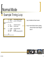
Normal Mode
Example Timing Loop
Init:
ldi
r16,0x07
out TCCR0,r16
;============================
TDelay:
ldi
r16,0
out TCNT0,r16
; set the prescaler for the counter
; prescaler = 1024 (ATmega128)
TLoop:
; read timer/counter value
; is it $63?
; if not $63, read it again (until $63)
in
r17,TCNT0
cpi r17,0x63
brne Tloop
; initialize timer/counter 0
; starts the counter
Step 1: Initialize the Timer/Counter
Step 2: Start the Timer/Counter: placing
a 0 in the Timer/Counter Register
starts it
done
;=================================
11/29/2010
12
Normal Mode
Example Timing Loop
Init:
ldi
r16,0x07
out TCCR0,r16
;============================
TDelay:
ldi
r16,0
out TCNT0,r16
; set the prescaler for the counter
; prescaler = 1024 (ATmega128)
Step 1: Initialize the Timer/Counter
; initialize timer/counter 0
; starts the counter
Step 2: Start the Timer/Counter
TLoop:
; read timer/counter value
; is it $63?
; if not $63, read it again (until $63)
Step 3: check for the calculated value
in
r17,TCNT0
cpi r17,0x63
brne Tloop
done
;=================================
In this case, the Timer/Counter will
increment its count every 1024 clock
pulses (every 102.4 us). This loop keeps
checking until the Timer/Counter gets to
99 (0x63). So the timer delays for:
100 * 102.4 us = 10.24ms
Note: count from 0 to 99 is 100
11/29/2010
13
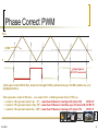
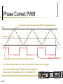
Phase Correct PWM
We will use Phase Correct PWM most of the
time
11/29/2010
PWM for short (as opposed to fast or CTC
modes)
14
Phase Correct PWM1
We will need the following registers:
11/29/2010
TCCR0: Timer/Counter Control Register 0
TNCT0: Timer/Counter 0
OCR0: Output Compare Register 0
The generated PWM waveform will appear
on the OC0 pin
1: Generating PWM signals using Timers in the ATMega chip, http://mil.ufl.edu/~achamber/servoPWMfaq.html
15
Phase Correct PWM
We will need the following registers:
TCCR0: Timer/Counter Control Register 0
TNCT0: Timer/Counter 0
To hold the value of the counter
OCR0: Output Compare Register 0
11/29/2010
To initialize the Timer/Counter and set the prescaler
Holds the count value for which the PWM signal will
toggle
16
Phase Correct PWM
Max
0
Initial Timer/Counter value is 0 (gets the counter started)
11/29/2010
17
Phase Correct PWM
Max
And starts counting up ……
0
Initial Timer/Counter value is 0 (gets the counter started)
11/29/2010
18
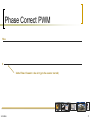
Phase Correct PWM
The Timer/Counter will count up to 0xFF
Max
0
Initial Timer/Counter value is 0 (gets the counter started)
11/29/2010
19
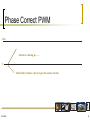
Phase Correct PWM
The Timer/Counter will count up to 0xFF
Max
0
Initial Timer/Counter value is 0 (gets the counter started)
Then it will count down to 0 ……
11/29/2010
20
Phase Correct PWM
The Timer/Counter will count up to 0xFF
Max
0
Initial Timer/Counter value is 0 (gets the counter started)
Then it will count down to 0, then up to some maximum …….
11/29/2010
21
Phase Correct PWM
The Timer/Counter will count up to 0xFF
Max
0
Initial Timer/Counter value is 0 (gets the counter started)
Then it will count down to 0, then up to some maximum, then down to 0 …….
11/29/2010
22
Phase Correct PWM
The Timer/Counter will count up to 0xFF
Max
0
Initial Timer/Counter value is 0 (gets the counter started)
Then it will count down to 0, then up to some maximum, then down to 0, etc.
11/29/2010
23
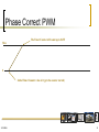
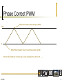
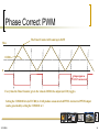
Phase Correct PWM
The Timer/Counter will count up to 0xFF
Max
OCR0
0
The timer will count up, eventually getting to the value in OCR0. It will then continue to count to 0xFF and then
start counting down, eventually getting to the value in OCR0 again, then continuing its count down to 0.
11/29/2010
24
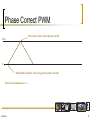
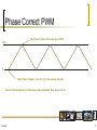
Phase Correct PWM
The Timer/Counter will count up to 0xFF
Max
OCR0
0
Output signal on
OC0
Every time the Timer/Counter gets to the value in OCR0, the output (on OC0) toggles
11/29/2010
25
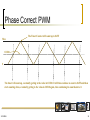
Phase Correct PWM
The Timer/Counter will count up to 0xFF
Max
OCR0
0
Output signal on
OC0: Non-inverted
Every time the Timer/Counter gets to the value in OCR0, the output (on OC0) toggles
Setting the COM01:0 bits (in TCCR0) to 2 will produce a non-inverted PWM. An inverted PWM output
can be generated by setting the COM01:0 to 3
11/29/2010
26
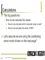
Calculations
The big questions:
How do we calculate the values:
11/29/2010
How do we calculate which prescaler value to use?
How do we calculate the value OCR0?
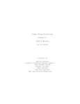
Let’s assume we are using the positioning
servo motor shown on the next page2
2: DC Servo Motor Control, http://www.digisoft.com.pk/Projects/dc-servo-motor-control
27
Calculations
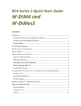
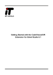
3 pins: Gnd, Vcc, and Control
The PWM signal should have a
period of 10 to 30ms.
11/29/2010
2: DC Servo Motor Control, http://www.digisoft.com.pk/Projects/dc-servo-motor-control
28
Calculations
3 pins: Gnd, Vcc, and Control
The PWM signal should have a
period of 10 to 30ms. A pulse 0f 1.5ms
sets the neutral position (90°), 1ms
sets the left position (0°) and 2ms sets
the right position (180°)
11/29/2010
29
Calculations
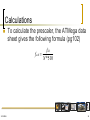
To calculate the prescaler, the ATMega data
sheet gives the following formula (pg102)
fclk
foc 0 =
N *510
11/29/2010
30
Calculations
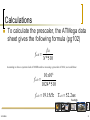
To calculate the prescaler, the ATMega data
sheet gives the following formula (pg102)
fclk
foc 0 =
N *510
Assuming we have a system clock of 10MHz and we are using a prescaler of 1024, we would have:
10 x106
foc 0 =
1024*510
foc 0 = 19.15 Hz
Toc 0 = 52.2ms
Too high
11/29/2010
31
Calculations
To calculate the prescaler, the ATMega data
sheet gives the following formula (pg102)
fclk
foc 0 =
N *510
Assuming we have a system clock of 10MHz and we are using a prescaler of 1024, we would have:
10 x106
foc 0 =
256*510
foc 0 = 76.59 Hz Toc 0 = 13.05ms
11/29/2010
32
Calculations
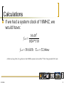
If we had a system clock of 16MHZ, we
would have:
16 x106
foc 0 =
1024*510
foc 0 = 30.63Hz Toc 0 = 32.64ms
A little too long. But, let’s go back to the 10MHz system clock and the 77Hz (13ms period) OC0 clock
11/29/2010
33
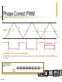
Phase Correct PWM
Max
OCR0
0
Output signal on
OC0: Non-inverted
It’s probably easier to use a non-inverted signal.
Set COM01:0 to 2 (in TCCR0), CS02:0 to 7 for a prescaler of 1024, and WGM01 to 0 and WGM00 to 1 for
PC PWM.
11/29/2010
34
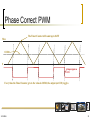
Phase Correct PWM
Max
OCR0
0
Output signal on
OC0: Non-inverted
A full count: from OCR0 to Max, down to 0 (through OCR0), and then back up to OCR0 would be one cycle
(highlighted above).
This represents a count of 256 twice – or a count to 512 – which represents 13ms (1/77Hz), so
• a count to ≈40 represents about 1 ms (0°) count from 20 down to 0 and up to 20 (total of 40)
OCR0=20
• a count to ≈59 represents about 1.5ms (90°) count from 30 down to 0 and then up to 30 (total of 60) OCR0=30
• a count to ≈78 represents about 2ms (180°) count from 39 down to 0 and up to 39 (total of 78)
OCR0=39
11/29/2010
35
Speed Control
11/29/2010
36
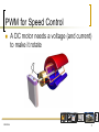
PWM for Speed Control
11/29/2010
A DC motor needs a voltage (and current)
to make it rotate
37
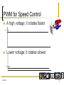
PWM for Speed Control
A high voltage: it rotates faster
V = 5v
Lower voltage: it rotates slower
V = 0.5v
11/29/2010
38
PWM for Speed Control
11/29/2010
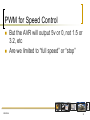
But the AVR will output 5v or 0, not 1.5 or
3.2, etc
Are we limited to “full speed” or “stop”
39
PWM for Speed Control
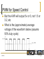
But the AVR will output 5v or 0, not 1.5 or
3.2, etc
What is the (approximate) average
voltage of the waveform below (assume
50% duty cycle):
V = 5v
11/29/2010
40
PWM for Speed Control
But the AVR will output 5v or 0, not 1.5 or
3.2, etc
What is the (approximate) average
voltage of the waveform below (assume
50% duty cycle):
V = 5v
Vave = 2.5v
11/29/2010
41
PWM for Speed Control
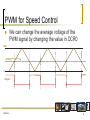
We can change the average voltage of the
PWM signal by changing the value in OCR0
Max
OCR01
0
Output1
11/29/2010
42
PWM for Speed Control
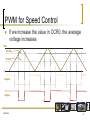
If we increase the value in OCR0, the average
voltage increases
Max
OCR02
OCR01
0
Output1
Output2
11/29/2010
43
PWM for Speed Control
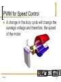
11/29/2010
A change in the duty cycle will change the
average voltage and therefore, the speed
of the motor
44
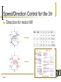
Speed/Direction Control for the 3π
Direction for motor M1
Forward
Reverse
11/29/2010
45
Speed/Direction Control for the 3π
Direction for motor M2
Forward
Reverse
11/29/2010
46
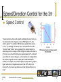
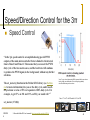
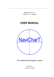
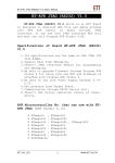
Speed/Direction Control for the 3π
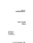
Speed Control
“Speed control is achieved by rapidly switching the motor between
two states in the table. Suppose we keep PD6 high (at 5 V, also
called a logical “1”) and have PD5 alternate quickly between low
(0 V or “0”) and high. The motor driver will switch between the
“forward” and “brake” states, causing M1 to turn forward at a
reduced speed. For example, if PD6 is high two thirds of the time (a
67% duty cycle), then M1 will turn at approximately 67% of its full
speed. Since the motor voltage is a series of pulses of varying width,
this method of speed control is called pulse-width modulation
(PWM). An example series of PWM pulses is shown in the graph at
right: as the size of the pulses decreases from 100% duty cycle
down to 0%, the motor speed decreases from full speed down to a
stop.”3
11/29/201
0
3: From the Pololu 3Pi User’s manual, http://www.pololu.com/docs/0J21/5.c
47
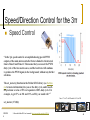
Speed/Direction Control for the 3π
Speed Control
“In the 3pi, speed control is accomplished using special PWM
outputs of the main microcontroller that are linked to the internal
timers Timer0 and Timer2. This means that you can set the PWM
duty cycle of the two motors once, and the hardware will continue
to produce the PWM signal, in the background, without any further
attention.
The set_motors() function in the Pololu AVR Library (see Section
6.a for more information) lets you set the duty cycle, and it uses 8bit precision: a value of 255 corresponds to 100% duty cycle. For
example, to get 67% on M1 and 33% on M2, you would call: ”3
Note: 171 = 67% of 255 and 84 = 33% of 255
set_motors (171,84);
11/29/201
0
3: From the Pololu 3Pi User’s manual, http://www.pololu.com/docs/0J21/5.c
48
Speed/Direction Control for the 3π
Speed Control
“In the 3pi, speed control is accomplished using special PWM
outputs of the main microcontroller that are linked to the internal
timers Timer0 and Timer2. This means that you can set the PWM
duty cycle of the two motors once, and the hardware will continue
to produce the PWM signal, in the background, without any further
attention.
The set_motors() function in the Pololu AVR Library (see Section
6.a for more information) lets you set the duty cycle, and it uses 8bit precision: a value of 255 corresponds to 100% duty cycle. For
example, to get 67% on M1 and 33% on M2, you would call: ”3
Note: To get a slowly decreasing PWM sequence like the one shown
in the graph, you would need to write a loop that gradually
decreases the motor speed over time.
Note: 171 = 67% of 255 and 84 = 33% of 255
set_motors (171,84);
11/29/201
0
3: From the Pololu 3Pi User’s manual, http://www.pololu.com/docs/0J21/5.c
49
PWM on Timer/Counter 1
(a 16-bit Timer/Counter)
11/29/2010
50
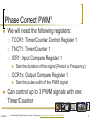
Phase Correct PWM1
We will need the following registers:
TCCR1: Timer/Counter Control Register 1
TNCT1: Timer/Counter 1
ICR1: Input Compare Register 1
OCR1x: Output Compare Register 1
11/29/2010
Sets the duration of the signal (Period or Frequency)
Sets the pulse width of the PWM signal
Can control up to 3 PWM signals with one
Timer/Counter
1: Generating PWM signals using Timers in the ATMega chip, http://mil.ufl.edu/~achamber/servoPWMfaq.html
51
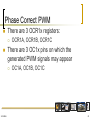
Phase Correct PWM
There are 3 OCR1x registers:
There are 3 OC1x pins on which the
generated PWM signals may appear
11/29/2010
OCR1A, OCR1B, OCR1C
OC1A, OC1B, OC1C
52
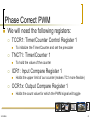
Phase Correct PWM
We will need the following registers:
TCCR1: Timer/Counter Control Register 1
TNCT1: Timer/Counter 1
Holds the upper limit of our counter (makes TC1 more flexible)
OCR1x: Output Compare Register 1
11/29/2010
To hold the value of the counter
ICR1: Input Compare Register 1
To initialize the Timer/Counter and set the prescaler
Holds the count value for which the PWM signal will toggle
53
Phase Correct PWM
The Timer/Counter will count up to 0xFFFF or the number in ICR1
Max
OCR1x
0
Initial Timer/Counter value is 0 (gets the counter started)
Output signal on OC1x
Every time the Timer/Counter gets to the value in OCR1x, the output (on OC1x) toggles
There are three OCR1x registers (OCR1A, OCR1B, and OCR1C)
There are three OC1x output lines (OC1A, OC1B, and OC1C)
11/29/2010
54
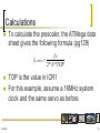
Calculations
To calculate the prescaler, the ATMega data
sheet gives the following formula (pg129)
foc1PWM
11/29/2010
fclk
=
2* N * TOP
TOP is the value in ICR1
For this example, assume a 16MHz system
clock and the same servo as before
55
Calculations
3 pins: Gnd, Vcc, and Control
The PWM signal should have a
period of 10 to 30ms. A pulse 0f 1.5ms
sets the neutral position (90°), 1ms
sets the left position (0°) and 2ms sets
the right position (180°)
11/29/2010
56
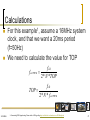
Calculations
For this example1, assume a 16MHz system
clock, and that we want a 20ms period
(f=50Hz)
We need to calculate the value for TOP
foc1PWM
fclk
=
2* N * TOP
fclk
TOP =
2* N * foc1PWM
11/29/2010
1: Generating PWM signals using Timers in the ATMega chip, http://mil.ufl.edu/~achamber/servoPWMfaq.html
57
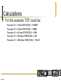
Calculations
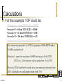
For this example TOP could be:
Prescaler N = 1 then TOP(ICR1) = 160000
Prescaler N = 8 then TOP(ICR1) = 20000
Prescaler N = 64 then TOP(ICR1) = 2500
Prescaler N = 256 then TOP(ICR1) = 625
Prescaler N = 1024 then TOP(ICR1) = 156.25
11/29/2010
58
Calculations
For this example TOP could be:
Prescaler N = 1 then TOP(ICR1) = 160000
Prescaler N = 8 then TOP(ICR1) = 20000
Prescaler N = 64 then TOP(ICR1) = 2500
Prescaler N = 256 then TOP(ICR1) = 625
Prescaler N = 1024 then TOP(ICR1) = 156.25
You cannot use prescaler 1 or 1024 to generate a 50 Hz PWM with a
16 MHz system clock:
Prescaler 1 cannot be used since 160000 too large to fit in TCR1.
(TCR1 is a 16 bit register with a range from 0 to 65535)
Prescaler 1024 should not be used since you cannot put decimals into
ICR1 (although you could approximate with 156)
11/29/2010
59
Calculations
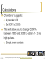
Chambers1 suggests:
This will allow you to change OCR1A
between 1000 and 2000 to obtain 1 - 2 ms
high pulses.
11/29/2010
A prescaler of 8
Set ICR1 to 20000.
Simple, even numbers
1: Generating PWM signals using Timers in the ATMega chip, http://mil.ufl.edu/~achamber/servoPWMfaq.html
60
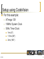
Setup using CodeVision
For this example:
ATmega 128
16MHz System Clock
50Hz Timer Clock
11/29/2010
1ms (0°)
1.5ms (90°)
2ms (180°)
61
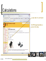
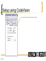
Setup using CodeVision
Select the ATmega chip and the frequency
11/29/2010
62
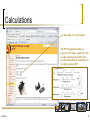
Setup using CodeVision
Select the ATmega chip and the frequency
Click on the Timers tab and then on the Timer1 tab
11/29/2010
63
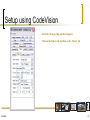
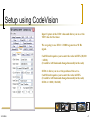
Setup using CodeVision
Select 2000.000 kHz for the Clock Value.
These clock values are calculated by taking the System clock
you entered on the first page and dividing it by the various
prescalers.
What you are actually setting here is what to divide the
system clock by in order get these various Timer speeds
11/29/2010
64
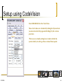
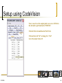
Setup using CodeVision
Under Mode, select Ph. & fr. cor. PWM top=ICR1
This is Phase and Frequency correct PWM mode with ICR1
holding the top value.
11/29/2010
65
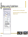
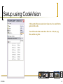
Setup using CodeVision
Timer1 on the ATMega128 can control 3 different servos
using Out A, Out B, and Out C.
We are only going to control one servo to start off...
Select Non-Inv. from the Out. A pull down menu.
Note: If this option isn’t shown, you chose the wrong selection under “Mode”
11/29/2010
66
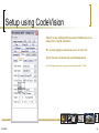
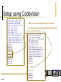
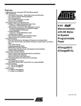
Setup using CodeVision
Input Capture is the ICR1 value and allows you to set the
TOP value for the timer.
We are going to use ICR1 = 20000 to generate a 50 Hz
signal.
CodeWizard requires you to enter the value in HEX (20,000
= 4E20).
(It could be left blank and changed manually in the code)
OCR1A allows you to set the position of the servo.
CodeWizard requires you to enter the value in HEX.
(It could be left blank and changed manually in the code)
OCR1A = 1000 (=0x03e8)
11/29/2010
67
Setup using CodeVision
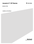
Now we need to set the output pin for our servo. OCR1A is
the alternative port function for PORT B.5
Click the Ports tab and then the Port B tab.
Click on the word "In" to change it to "Out"
Leave the output value at 0
11/29/2010
68
Setup using CodeVision
Click on the File menu and select Generate, Save and Exit to
generate the code.
You will be asked the name three files: the .c file, the .prj
file, and the .cwp file.
11/29/2010
69
Setup using CodeVision
This is the section of code generated by CodeVision
Note: decimal values could be entered here instead of the
hex values in the wizard
11/29/2010
70
Setup using CodeVision
This will position the servo motor:
while (1)
{
OCR1A = 1000;
delay_ms (5000);
OCR1A = 2000;
delay_ms (5000);
};
11/29/2010
//position the servo to the left – 0 degrees
//delay for 5 seconds
//position the servo to the right – 180 degrees
//delay for 5 seconds
71
Summary
In this topic we discussed:
The operation of an 8 bit timer/counter in an
AVR microcontroller
How to use the timer/counter to generate a
PWM signal
How PWM signals are used to control servo
motors
11/29/2010
Position control
Speed control
72