1
^mmg
m m
u
O M I T S , Inc. 1977
First P r i n t i n g , J u n e , 1977
2450 AtamoS.E./Atbuquerque, New Mexico87106
TABLE OF CONTENTS
Section
1.
INTRODUCTION
1-1.
1-2.
1-3.
1-4.
1-5.
2.
3.
Page
Introduction to this Manual
Loading and Initializing DOS
Program Development Procedure
Notation and Definitions
DOS Input Conventions
1
3
3
9
14
17
. . .
T9
2-1.
2-2.
2-3.
2-4.
2-5.
21
21
23
25
28
Introduction to the Monitor
Input from the Console
Monitor Commands
Monitor Error Messages
File Name Conventions
TEXT EDITOR
31
3-1.
Introduction
33
3-2.
Edit Commands
34
ASSEMBLER
5.
4-1. Statements
4-2. Addresses
4-3. Op-Codes
4-4. Assembler Error Messages
LINKING LOADER
5-1.
5-2.
5-3.
Introduction
Address Chaining
Relocatable Object Code Module Format
DEBUG
6-1.
6-2.
6-3.
6-4.
6-5.
6-6.
7.
.
MONITOR
4.
6.
'
43
.
46
47
52
71
73
75
77
77
SI
Introduction
Display
Modify
Breakpoints
Controlling Execution
Using Debug with Relocated Programs
S3
S7
37
88
89
90
MISCELLANEOUS SYSTEM PROGRAMS
91
7-1.
7-2.
7-3.
7-4.
93
93
93
95
INIT..
CNS
SYSENT
LIST
MS
June, 1977
^
APPENDICES
A.
B.
C.
D.
E.
F.
ASCII Character Codes
Disk Information
Monitor Calls
Absolute Load Tape Format
The File Copy Utility
Bootstrap Loaders
99
101
103
111
112
121
INDEX .
127
oos
1
June, 1977
L
oos
^ ^
June. 1977
1/(2
Blank)
J
1.
INTRODUCTION
1-1.
Introduction to This Manual
The Altair Disk Operating System (DOS) is a system for developing
and running Assembly Language programs.
several system programs.
It consists of a Monitor and
The parts of this manual describe the various
components of the system.
Chapter 2—the Monitor.
The Monitor provides control and disk
file management for all of DOS.
Monitor Input/Output routines are avail
able to any program running under DOS.
Chapter 3—the Text Editor.
and saves ASCII coded files.
The Editor (EDIT) creates, modifies
Typical Editor files include Assembly
Language programs and data.
Chapter 4—-the Assembler.
The Assembler (ASM) converts symbolic
Assembly Language programs into relocatable machine code modules.
Chapter 5—the Linking Loader.
The Linking Loader (LINK) loads
the relocatable object code modules into memory, assigns addresses to
symbols and resolves external references.
Chapter 6—Debug.
Debug is a versatile symbolic debugging program
With Debug, the programmer can interrupt execution of a program, examine
and modify the contents of register and memory locations.
Chapter 7—Miscellaneous System Programs.
Console (CNS) transfers command of the Monitor from one terminal
device to another.
Initialize (INIT) allows the system parameters (amount of memory,
number of disks, etc.) to be changed without reloading the system.
1*2-
Loading and Initializing DOS
When the computer is first turned on, there is nothing of value
in the semiconductor read/write memory.
Therefore, before DOS can be
used, the Monitor must be loaded from disk.
program, the loader.
This requires another
The loader may reside in read-only memory or may
be loaded from paper tape or cassette.
A.
Systems with a Disk Boot Loader PROM mounted in the proper
slot of a PROM Memory Card have the loader program readily
available in non-volatile memory.
MS
June, 1977
to load DOS with the DBL PROM:
Use the following procedure
1.
Turn on the power to the computer, disk drives and peri-
2.
Raise STOP and RESET simultaneously and then release them.
pherals.
3.
Raise switches A15-A8 and lower switches A7-A0.
4.
Actuate EXAMINE.
5.
Make sure the DOS diskette is mounted in disk drive 0 ,
that the door is closed and the disk has come up to speed
(approximately 5 seconds).
6.
Enter sense switch settings for the terminal I/O board
7.
Press RUN.
from Table 1-A.
DOS should start up and print MEMORY SIZE?
For the remainder
of the initialization procedure, see Section C below.
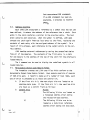
For systems without the DBL PROM, the loading procedure involves
entering a bootstrap loader from the computer front panel,
running it to load a disk loader program from paper tape or
cassette and then running that loader to load the Monitor from
disk.
The procedure for doing this is as follows:
1.
Turn on the power to the computer and peripheral devices.
2.
Raise the STOP and RESET switches simultaneously and then
3.
Make sure the terminal is on-line (on a T e l e t y p e ^ , this
release them.
means the mode switch is set to LINE).
Now enter the proper loader program for the device through
which the loader tape is to be entered.
The bootstrap loaders
are in Appendix F.
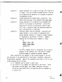
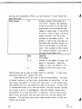
The bootstrap loaders are entered on the front panel switches
A7 - AO.
Each switch has two positions, up and down.
convention, up is designated as 1 and down as 0.
the eight switches represent one byte of data.
By
Therefore,
Each group of
three switches, starting from the right, can represent the
digits 0 through 7.
The leftmost two switches represent the
digits 0 through 3.
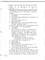
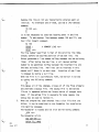
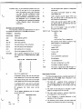
For example, to enter the octal number
315, the switches AO through A7 are set to correspond to the
following table:
COS
June, 1977
Switch
A7
A6
A5
A4
A3
A2
A1
AO
Position
up
up
down
down
up
up
down
up
Octal Digit
3
5
1
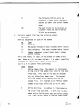
The data bytes of the loader programs are shown in octal and
are to be entered on AO - A7 in this manner.
To enter the
programs:
4.
Put switches AO -. A15 in the down position.
5.
Raise EXAMINE.
6.
Put the first loader program data byte in switches AO - A 7 .
7.
Raise DEPOSIT.
8.
Put the next data byte in AO - A7.
9.
Depress DEPOSIT NEXT
10.
Repeat steps 8 and 9 for each successive data byte until
the loader is completely entered.
Now check the loader to make sure it has been entered correctly:
11.
Put switches AO - A15 in the down position.
12.
Raise EXAMINE.
13.
Check to see that the lights DO - 07 correspond to the
t
correct data byte for the first location. A light on
indicates 1; off means 0.
The rightmost three lights
correspond to the rightmost octal digit.
The next three
lights represent the middle digit and the leftmost two
lights represent the left digit.
If the data byte is correct, go to step 16.
If the data byte is not correct, go to step 14.
14.
Put the correct value in switches AO - A7.
15.
Oepress DEPOSIT.
16.
Oepress EXAMINE NEXT.
17.
Check each successive byte by repeating steps
13-16
until the whole loader is checked.
18.
If there were any incorrect bytes, check the whole loader
again to see that they were corrected.
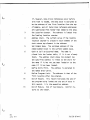
Now the paper tape or cassette labelled DISK LOADER can be read.
for the paper tape version, put the tape in the reader and make
sure it is positioned on the leader.
The leader is the section
of tape at the beginning with a series of 302o characters (3 of
8 holes punched). For the cassette version, put the cassette in
the reader and make sure it is completely rewound.
19.
Put switches AO - A15 in the down position.
20.
Raise EXAMINE.
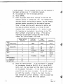
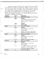
21.
Enter the proper sense switch settings for the load and
terminal devices in switches A8 - A15.
The rightmost four
switches contain the load device setting, and the leftmost
switches contain the setting for the terminal devices.
Table 1-A shows both the octal sense switch setting and
the load and terminal switches to be raised for each
standard Altair system peripheral.
If a device is used
for interface to the terminal, the switches in the "Terminal Switches" column must be raised.
If the device
interfaces the peripheral through which DOS is being
loaded, the "Load Switches" are raised.
Sense Switch
Setting
Terminal
Switches
Load
Switches
Channels
2SI0
(2 stop bits)
0
None
None
20,21
2SI0
(1 stop bit)
1
A12
A8
20,21
SIO
2
A13
A9 .
0,1
ACR
3
A13,A12
A9,A8
6,7
4PI0
4
A14
A10
40,41,
42,43
PIO
5
A14,A12
A10,A8
4,5
Non-Standard
terminal
14
No terminal
15
22.
Start the loading process.
If the load device is connected
to the computer through an 88-SIO A , B or C or an 88-PIO
board, start the tape reader and then press the RUN switch
on the computer front panel.
For the 2SI0 or 4PI0 boards,
press RUN and then start the reader.
and start the cassette.
For the ACR, rewind
Listen to the signal from the
tape (through an auxiliary earphone).
When the steady tone
changes to a warble, press RUN on the computer.
90S
6
June, 1977
If the checksum loader detects a loading error, it turns on
the Interrupt Enable light and stores the ASCII code of an
error letter in memory location 0.
The error letter is also
transmitted over all terminal data channels.
If a terminal is
connected to one of these ports, it prints the error letter.
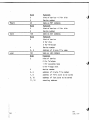
The error letters are as follows:
C
Checksum error.
If the checksum on the DOS disk file
does not equal the checksum generated by the loader, C
error results. "The error may not occur if the diskette
is loaded again.
If it does occur three times consecu-
tively, the loader tape or diskette is at fault and
must be replaced.
M
Memory error.
Data from the disk does not store properly.
The location at which the error occurred is stored at
locations 1 and 2 absolute.
0
Overlay error.
An attempt was made to load data over
the loader.
1
Invalid Load Device.
The setting of the sense switches
is incorrect.
C.
When the Monitor has been loaded correctly, it responds with
the first initialization question.
MEMORY SIZE?
Here the programmer may specify the amount of memory, in bytes,
to be used by DOS.
Typing a carriage return or zero causes
DOS to use all of the read/write memory in the system.
The
next question is
INTERRUPTS?
Typing Y enables input interrupts and Typing N or carriage
return disables them.
If interrupts are enabled, special-
characters may be used to control program execution.
NOTE
Input interrupt features may be used only if the input interface board is strapped to accept interrupts.
for information on 1/0 interrupts.
See Section 2-2
If interrupts are not
strapped, the answer to the INTERRUPTS? question must be N.
The next question is
HIGHEST DISK NUMBER?
to which the programmer responds with zero if there is one
disk in the system, 1 if there are two disks and so on.
The
next question is
HOW MANY DISK FILES?
to which the programmer responds with the number of disk
files (both sequential and random) to be open simultaneously.
Responding with a carriage return sets the number of files at
zero.
Finally, DOS asks
HOW MANY RANDOM FILES?
Again, the programmer responds with a number or with a carriage
return, which specifies zero random files.
To save time, especially when a slow terminal is in use, all
of the initialization answers can be entered at once with the
parameters separated by spaces.
MEMORY SIZE?
For example:
0 Y 1 2 0
tells DOS that
1.
it is to use all available memory,
2.
input interrupts are enabled,
3.
there are two disk drives in the system,
4.
two sequential and
5.
no random disk files are to be open at any given time.
When DOS has been properly initialized, it prints the following prompt message
DOS MONITOR VER x.x
The Monitor prints a period to indicate that it is now ready
to receive commands.
oos
June, 1977
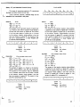
1*3*
Program Development Procedure
DOS is designed to allow the translation of an Assembly language
program on paper to an operating Machine Language program with a minimum
of time and effort.
The process involves entering the Assembly language
program into a disk file with the Text Editor, translating the file to
Machine language with the Assembler and loading the program into memory
with the Linking Loader.
Before the process can proceed, the disks in use must be mounted
with the MNT command.
To mount disk 0 , the following command is used:
_^MNT0<cr>
where <cr> means carriage return.
Other disks may be mounted in the
same command by typing their numbers after the zero, separated by spaces.
Mounting the disk(s) tells DOS the location of all the files and
free space on each disk.
If an attempt is made to run a program before
the disk on which it is stored is mounted, a PROGRAM NOT FOUND error
will result.
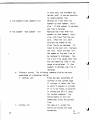
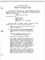
1.
The first step in program development is to enter the program
into a disk file with the Text Editor.
The Editor is loaded
from disk and run by the following command:
JEDIT<cr>
When it is loaded, it prints
DOS EDITOR VER x.x
ENTER FILE NAME
to which the user replies with the name of the file to be
entered or edited.
The editor then prints
ENTER DEVICE NUMBER
which is answered with the number of the disk drive where the
file is stored.
Assume that an Assembly language program called SAMP is entered
into a file on disk drive 0.
The Editor is run with the fol-
lowing command:
^EDIT SAMP 0 <cr>
The file name (SAMP) and device number (disk 0) can be entered
in the EDIT command to avoid the necessity of asking the file
name and device number.
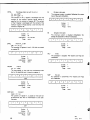
cs
!„n. is??
The Editor searches disk drive 0 for
a file name SAMP to edit.
the following messages:
If it finds no such file, it prints
CREATING FILE
00100
00100 Is the number of the first line of the file.
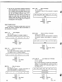
Now, all
that is necessary is to enter the lines of'the program.
00100
LDA
IER
LOAD MULTIPLIER<cr>
00110
LHLO
CAND
LOAD MULTIPLICAND<cr>
After each carriage return, the next line number is generated
automatically so that the next line can be entered.
This
process continues until all the lines of the program have been
entered.
00340
PROD DB
00350
END <cr>
00360
<cr>
0,0 <cr>
To stop the generation of line numbers, type a null line (just
a <cr>).
The Editor prints an asterisk (*) to indicate it is
ready to accept new commands.
To check the file in order to
make sure it has been entered without error, type
IP
This prints all of the lines on the current page with their
line numbers.
In this example, there is only one page (see
paging commands, p. 40 , for an explanation of program pages),
so the P command prints the whole file.
The output appears as
follows:
*p
10
00100
LDA
IER
00110
LHLD
CAND
00120
SHFTR
RAR
00130
SHFTR
RAR
00240
CAND
DB
64
00250
PROD
DB
0,0
oos
June. 1977
Suppose the line at 120 was inadvertantly entered again at
line 130.
To eliminate one of them, use the D (for Delete)
command.
130 <cr>
*
It is not necessary to type the leading zeros in the line
number.
To add another line between number 100 and 110, use
the I (for Insert) command.
100
00105 ;
A COMMENT LINE <cr>
00107 <cr>
The line number specified is that of the existing line immediately before the desired position of the new line.
The
Editor generates a line number halfway between the two existing
lines.
After typing the new line, a <cr> causes another
number to be generated halfway between the inserted line and
the next existing line.
New lines can be inserted in this
manner until there is no more room.
Insertion of new lines
is stopped by typing a null line.
When the file is in satisfactory form, the Editor is exited
by typing the following command:
This makes all of the changes, closes all of the files properly
and provides a backup file.
The backup file is the edited
file as it appeared before the latest series of changes were
made.
If the edited file is unusable for some reason, the
backup may be used to replace it.
When the program has been entered into a disk file with the
Editor, it may be submitted to the Assembler for translation
into machine language.
The Assembler is loaded and run with the following command:
J\SM <cr>
The Assembler prints
DOS ASM VER x.x
ENTER FILE NAME
!
The user enters the name of the Assembly language program file
and a <cr>.
The Assembler then prints
ENTER DEVICE NUMBER
to which the user replies with the number of the disk drive on
which the file resides and a <cr>.
At this point, the Assembler proceeds immediately to assemble
the program in the specified file.
In our example, we can type
J\SM SAMP 0 <cr>
to avoid having the computer ask for the file name and drive
number.
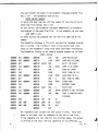
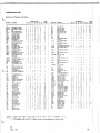
The Assembler produces a file with the machine language program
and a listing.
The listing is that of the source code (the
input to the Assembler) along with other pertinent information.
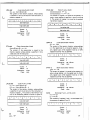
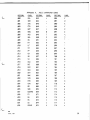
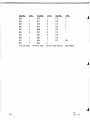
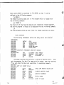
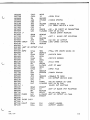
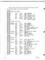
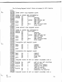
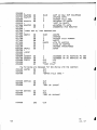
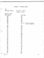
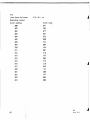
The Assembler listing of our sample program appears as follows:
SAMP LISTING
072
000033'
000003
052
000034'
000006
037
000007
322
000012
077
000013
353
000014
052
000017
031
000020
042
000023
353
000024
051
000025
322
000030
303
000100
000120
000024'
000036'
000036'
SHFTR
LDA
IER
LOAD MULTIPLIER
LHLD
CAND
LOAD MULTIPLICAND
SCAN
JUMP IF NO CARRY
RAR
SHIFT 'ER RIGHT
000130
JNC
000135
CMC
000140
XCHG
000150
LHLD
PROD
LOAD PROD IN H,L
000160
DAD .
D
ADD 'CAND TO PROD
000170
SHLD
XCHG
000190
SCAN
SAVE 'CAND IN C,D
STORE PROD
PROD
H
SHFTR
JMP
REPEAT IF NOT FINISHED
JUMP TO MONITOR. WHEN
000228
000033
RESTORE 'CAND
SHIFT LEFT
DAD
JNC
000225
TURN OFF CARRY
FINISHED
000033
040
000230
IER
DB
32
000034
200
000240
CAND
DB
128,0
000036
000250
PROD
DB
000040
000260
END
The rightmost four columns are the source listing.
Note that
there is not much room for comments at the end of the line.
If the comments are too long for the allotted space, the excess
is printed on the next line and operation is not affected. pQg
12
i
June. 1977
The next column to the left is the Text Editor's line number.
The next two columns are the octal representation of the object
code (the output of the Assembler).
If the source instruction
does not produce a machine instruction (END, for example),
this column is left blank.
If the source instruction defines
the contents of memory (DB or DW, for example), those contents
appear in the object code column.
Source instructions that
produce object code instructions (LDA, for example) are represented by the octal instruction code and the address of the
operand.
cated.
Addresses followed by an apostrophe are to be reloTheir actual addresses are not determined until the
program is loaded into memory.
Finally, the leftmost column is a list of the relative addresses
of the object code instructions and memory areas.
precedes the address, it indicates an error.
If a letter
The letter desig-
nates the nature of the error and the position indicates the
address where the error occurred.
A list of error letters and
their meanings is in section 4-4, p. 71.
If an error is detected by the Assembler, it can be corrected
by reentering the Text Editor and making the necessary changes.
The ability to pass programs rapidly from the Text Editor to
the Assembler and back makes DOS an extremely effective tool
for writing and debugging Assembly language programs.
Finally, the Linking Loader is used to load the program into
memory and execute the program.
The Linking Loader is loaded
typing the following command:
^ LINK <cr>
When the Linking Loader starts, it prints
DOS LINK VER 1.0
*
To load the sample program, type
^L SAMP 0 <cr>
If the file name and drive number had been omitted, LINK would
have asked for them.
This command causes LINK to load our
file into memory beginning at location 24000g.
Other starting
addresses can be specified (see Linking Loader, L command, p.
76), but the default value is adequate for our purposes.
The
following command causes the program to be executed:
^ X <cr>
This command causes control to be passed to,whatever program
begins at location 24000g. Again, other starting addresses
can be specified (.see Linking Loader, X command, p. 51).
If the program does not run as expected (and that is not
improbable), the program bugs can be tracked down by Debug.
For a description of the use of Debug, see Section 6, p. 83.
1-4.
Notation and Definitions
In the specification of command formats and examples, the follow-
ing notation conventions are used:
< >
Angle brackets enclose information that must be
supplied by the user
[ ]
* Square brackets enclose information that is optional
<cr>
Carriage return (ASCII 013) on most terminals, <cr>
<space>
a space (ASCII code 032)
Control/x
where x is a character, is typed by holding down the
and may be specified by the user.
is typed with the Return key.
Control key while typing the character.
In examples, characters output by the computer are underlined.
Information typed by the user is presented exactly as it is to be typed.
All punctuation and spacing must be observed.
The following definitions are used throughout this manual:
byte
eight bits of binary information.
Memory locations
each contain 1 byte of information and the ASCII
code uses 1 byte to represent 1 character,
file
set of information accessible to a program by name
or number.
Program modules, data blocks and infor-
mation transferred to or from I/O devices may all be
considered to be files.
In this manual, files are
divided into two broad classes:
Sequential and
Random.
j
14
I
MS
June. 1977
A Sequential file is organized as a string of bytes
of information.
From any point in a sequential file,
only the next byte may be accessed directly.
Data
bytes are written after the last existing byte of
the file.
Sequential files can be divided into two
types, depending upon how the data bytes are interpreted:
a) ASCII files in which each byte represents a character according to the American Standard Code for
Information Interchange (see Appendix A for a
table of ASCII codes) and
b) binary files in which the binary data are taken
as such with no code conversions applied.
Two
special types of binary files are distinguished
from other binary files by their contents.
Abso-
lute files are those which conform to the Absolute
Tape Dump format in Appendix B.
The Monitor's SAV
command produces absolute files.
Relocatable
files conform to the relocatable object code
module format in Section 5-3.
The Assembler pro-
duces relocatable files which the Linking Loader
can then load into memory.
Random files are organized as a series of records,
each of which may be accessed separately from the
rest.
Each record has a unique number which may be
used to read, modify or write on any record in the
file at any time.
The various system programs follow certain conventions for file names.
See section 2-7 for an explan-
ation of these conventions.
Appendix E shows an
example of the use of files in a DOS program.
program
an ordered set of machine and/or Assembler instructions that direct the computer to perform a given
series of operations.
The two major classes of
programs are system programs and user programs.
a) system programs are stored on disk in absolute
binary files and thus may be loaded and run
simply by typing the program's name to the
Monitor.
System programs run in memory imme-
diately above the Monitor and below user programs.
b) user programs are those programs that run in high
memory above the system programs.
The usual pro-
cedure for developing user programs is to construct them from one or more relocatable code
modules produced by the Assembler and linked
together by the Linking Loader.
For a discussion
of relocatable modules, see Section 5-3, page 77.
prompt
When the Monitor or a system program takes control,
it prints a message indicating which program is
running and whether it is ready to receive commands.
The Monitor prompts with a period (.) which precedes
each command.
Similarly, Editor and Linking Loader
commands are typed after an asterisk (*).
Debug and
the Assembler prompt only once after the program is
loaded.
The Monitor also prompts the programmer when insufficient information has been given in a command.
For example, if the programmer types
J1NT <cr>
the computer prints
ENTER DEVICE NUMBER
Typing the number and a carriage return causes the
command to be executed.
oos
J u n e , 1977
1-5.
DOS Input Conventions
All Input to DOS (as from a terminal) is handled through the
Monitor's input routine.
This routine has several properties which set
constraints on the form of input.
All 128 ASCII characters are accepted by the input routine except
characters of the form Control/x where x is any letter.
Some Control/
characters are used to control the input routine and the rest are ignored.
<cr> terminates a line.
input is taken as a new line,
The input buffer is cleared and subsequent
d i n e feed> is considered an input character.
The input buffer accepts the first 72 characters as one line of
input.
If more than 72 characters are input in a line, the contents of
the buffer are discarded and a new line is begun.
Special characters include the following:
a) Rubout deletes the last character in the buffer.
When Rubout
is typed, a backslash (\) and the last character in the buffer
are printed.
acter.
Each successive Rubout prints the previous char-
Typing another character prints another backslash and
the character.
are deleted.
All of the characters between the backslashes
If Rubout is typed with no characters in the
buffer, a <cr> is printed.
b) Control/U deletes the current contents of the input buffer.
c) Control/R displays the current contents of the input buffer.
Example:
EXAMPLE LENE\ENE\INE <Control/R>
EXAMPLE LIME
Typing three rubouts deleted the characters between the backslashes.
Typing Control/R displayed the final appearance of
the line.
d) Control/I is a tab character.
When a tab is printed, spaces
are printed so that the next character is printed at the start
of the next 8 space column.
The following special characters are recognized if input interrupts
are enabled (see p. 2 2 ) .
cos
June, 1977
17
Control/S
Causes execution of a program to pause until Control/Q
is typed.
This can be used to pause during a listing
or to pause during execution of a program to examine
intermediate values.
Control/Q
causes execution to resume after a Control/S.
Con-
trol /Q has no effect if no Control/S has been typed,
Control/C
causes execution of a program to be suspended and
control to be passed to the Monitor.
During the
execution of certain I/O operations (Mount, Open,
Kill, etc.), Control/C does not terminate execution
until the operation is completed,
Control/0
prevents output from the computer.
Execution pro-
ceeds normally, but no output is generated until
either another Control/0 is typed or another command
is requested by the Monitor or Editor.
Example:
Suppose the following Editor command is typed:
*P
00100
LDA
IER
00200
LHLD
CAND
<Control/0>
The Print command action is completed, but no output
appears on the terminal until the Editor's prompt
asterisk appears, requesting another command.
Other constraints are imposed by the system programs in use and
are discussed in the descriptions of the Editor, Assembler, Debug and
miscellaneous programs.
Some of the standards which apply to all of the
system programs are as follows:
a) All commands must be typed in upper case.
b) The fields of the command are separated by delimiters.
These
delimiters include space, tab, comma, semicolon and colon.
Colons are used specifically to separate multiple commands on
a single line.
oes! I
June,i'!977
c
oos
June. 1977
19/(42
Blank)
J
J
2.
THE MONITOR
2-1.
Introduction to the Monitor
The Monitor is the control center of the DOS system.
It is used
to load and execute system and user programs and to execute Input/
Output routines for all of the system's peripheral devices.
The Monitor is loaded first to load and execute all the other
system components.
It remains in memory at all times, passing control
back and forth to system and user programs and providing I/O services.
The Monitor's device-independent Input/Output system reduces programming effort.
The programmer could write a different input or output
routine for each I/O device used by a program.
But these device handler
routines are incorporated into the Monitor, so the programmer can perform
the desired information transfer simply by calling the Monitor.
Monitor
Calls are described in detail in Appendix C .
When DOS has been loaded and initialized, the Monitor starts up
and prints the following message.
DOS MONITOR VER x.x
This message is also printed when the Monitor is entered from another
program.
The period indicates that the Monitor is ready to receive
commands.
2-2.
Input from the Console
Input from the console keyboard is handled by a central Monitor
routine regardless of the system program that is running at the time.
This routine provides the following special characters and functions.
Rubout
deletes the last character in the input buffer.
Typing Rubout causes a backslash (\) and the last
character in the buffer to be printed.
Subsequent
Rubouts print the immediately previous character in
the buffer.
When a character other than Rubout is
typed, a second backslash and the character are
printed.
All the characters between the backslashes
are deleted.
Backarrow (*-) same as Rubout
oos
J u n e , 1977
Control/R
causes the current contents of the input buffer to
be printed on the console.
Example:
EXEMPLE LINE\ENIL ELPME\AMRLE<Control/R>
EXAMPLE
In this example, typing Rubout 10 times deleted the
characters between the backslashes; typing Control/R
displays the current appearance of the line.
Control/U
clears the input buffer.
<cr>
terminates a line of input.
The current contents
of the line buffer are passed to the program and
the line buffer is cleared.
If input interrupts are enabled, the following special character
functions are available:
Control/C
suspends execution of the current program and
Control/S
temporarily suspends execution of a program until
returns control to the Monitor.
Control/Q is typed.
Control/Q
causes execution of a program to be resumed after
Control/0
allows execution to proceed normally, but prevents
a Control/S
output to the terminal.
No output is printed until
another Control/0 is typed or another command is
requested by the Monitor or Editor.
To enable interrupts on the older I/O interface boards (PIO, SIO
A , B, C), install a jumper from the IN interrupt line'to PINT o r , if the
Vector Interrupt board is in use, to VI7.
On newer interface boards (2SI0, 4PI0), install the jumper between
PINT or VI7 to the interrupt request line for the input channel.
DOS
automatically assures that input interrupts are enabled.
For more information, see the manual for the interface board in
use.
cos
June, 1977
2-3.
Monitor Commands
The Monitor is directed to perform its functions by commands.
The general form of a Monitor command is as follows:,
<command code> [<field> <field>
. . .]
where the command code is the three letter designation of the command
to be performed and the fields are the required operands for the
specific command.
The fields are separated by spaces, tabs or other
legal delimiters.
If insufficient information is given in the operand
fields for a given command, the Monitor asks for the missing information
and will not proceed until the information is typed.
If the Monitor
cannot execute the requested command, it prints an error message which
indicates the reason the command could not be executed.
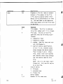
The following abbreviations and definitions are used in the descriptions of the Monitor commands:
delimiter
characters that separate the fields in a command.
Legal delimiters are <space>, tab (Control/1),
comma, semicolon and colon,
device
number of the device to be used in the command
action.
The Monitor at present supports only floppy
disk drives in the commands, so the term "device" is
interchangeable with the term "drive number."
file
name of the data or program file on which the
command action is to be performed,
list
a series of device numbers or file names separated
by delimiters.
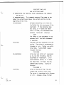
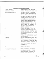
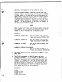
Table 2-A.
Monitor Commands
Connnand
Function
DEL <file><device>
deletes the named file from the indicated device,
DIN <devicex1ist>
initializes the listed disk drives by writing the
track and sector number in each sector.
Zeros are
written into each byte of each sector, destroying
any existing files and marking each sector as free.
The DOS disk is initialized at the factory and must
not be initialized again.
Doing so will destroy all
system programs as well as user files.
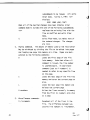
oos
June, 1977
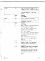
Command
Function
DIR <device>
Prints a directory of the files on the indicated
device.
See section 2-7 for an explanation of the
file name conventions.
DSM <device list>
Dismounts the disks on the listed device or devices.
A disk must be dismounted before it is removed from
a drive.
Failure to do so may cause file link
errors the next time the disk is read.
LOA <file><device>
Loads the named file into memory from the specified
device.
The file must be an absolute binary file.
The LOA command automatically adds # to the file
name.
MNT <device list>
Mounts the disks on the specified devices.
The MNT
command causes the system to read each specified
diskette and creates a table of unused space.
When
files are created or modified, the system checks the
table for unused sectors.
This command must be
given before the files on a disk may be accessed.
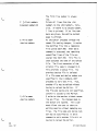
REN <old name>
Renames the file <old name> on the specified device
<new name>
to have a name <new name>.
<device>
RUN <file><device>
Loads the named file from the specified device and
runs it.
The file must be an absolute binary file.
A # sign is automatically added to the file name.
SAV <file><device>
Contents of memory from the first location to the
<lst 1ocation>
last location are saved as an absolute binary file
<last location><sa> With the specified name.
added to the file name.
A # sign is automatically
Any subsequent RUN command
causes execution to begin at <sa>.
If the input to the Monitor is not one of these commands, the
Monitor searches disk drive 0 for an absolute program file which has a
name corresponding to the input.
and run.
If such a file is found, it is loaded
The following system programs are run in this manner:
oos
June, 1977
ASM
Assembler - see chapter 4
EDIT
Text Editor - see chapter 3
DEBUG
Debug package - see chapter 6
LINK
Linking Loader - see chapter 5
INIT
Disk initialization program - see chapter 7
CNS
Console - see chapter 7.
Console allows the Monitor
command console to be changed to another
terminal.
Drive 0 must be mounted before running these programs.
2-4.
Monitor Error Messages
When the Monitor detects an error in the execution of a command
or a Monitor Call, it prints an error message and terminates execution
of the operation.
In the case of an error in a Monitor Call, the error
message is printed and control returns to the calling program.
A Monitor error message contains the following information:
Error Code
the error codes are given in Table 2-B
File Number
the number of the file that was being accessed when
RQCB Address
the address of the Request Control Block of the
the error occurred
Monitor Call that caused the error.
Opcode
the operation code of the Monitor Call that caused
Return Address
the address to which control would have returned
the error
had the error not occurred.
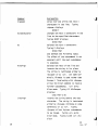
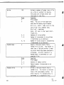
Table 2-B.
Error Codes
Error Code
Meaning
1
FILE TABLE ENTRY MISSING
The file table contains entries for thirteen disk files (numbered
. 0 - 1 2 ) and four other I/O files ( 0 - 3 ) .
If a file number other
than these is encountered, an error occurs.
2
DEVICE NOT IN PHYSICAL DEVICE TABLE
The following devices are listed in the physical device table:
Teletype or Teletype compatible terminal
Audio Cassette
aos
June,.197*
High-Speed Paper Tape Reader
Floppy Disk
An attempt to transfer information to or from another device
causes an error.
3
HANDLER NOT IN HANDLER TABLE
An attempt was made to perform an invalid operation on an I/O
device, for example, to output to a paper tape reader.
4
BOARD NOT IN I/O TABLE
The following I/O boards are in the I/O table:
2SI0
S I O A , B, a n d C
4PI0
PIO
Use of other boards is not supported.
5
SHORT DATA TRANSFER
The end of data transfer came before the specified number of bytes
was read or written.
6
CHECKSUM ERROR
When a program is loaded, the Monitor keeps a running sum of allthe bytes in each record.
is the checksum.
The least significant byte of this sum
At the end of the record, it is compared with
the checksum byte in the record.
If there is a discrepancy between
them, an error has occurred in loading the program and the Checksum
Error message is printed.
7
MEMORY ERROR
An attempt was made to write into a bad memory location.
This
could be a non-functioning read/write memory location or a location
in read-only memory.
10
BAD FILE NUMBER
A bad file number is one which has not been opened or which is
greater than the number of files allocated at initialization.
11
FILE LINK ERROR
During a disk file read, a sector was read which did not belong
to the file.
A FILE LINK ERROR often occurs after a disk has been
removed from a drive without being dismounted first.
12
I/O ERROR
A checksum error occurred in 18 successive disk read operations.
A checksum error on a disk read causes the disk controller automatically to re-read the sector.
'6
A Disk 1/0 Error indicates that
oos
June, 1977
the error is a permanent defect in the file, disk or disk drive.
c
13
BAD FILE MOOE
A sequential operation was attempted on a random file or vice
versa.
14
DEVICE NOT OPEN
An attempt was made to input or output a file through a device
which had not been opened to that file.
15
DEVICE NOT ENABLED
The door of a disk drive has not been closed, or the motor of the
drive has not had time to come up to full speed.
16
DEVICE ALREADY OPEN
An attempt was made to mount a disk which has already been mounted.
17
INTERNAL ERROR
DOS became confused.
Please report the circumstances of this
error to the MITS, Inc. Software Department.
20
OUT OF RANDOM BLOCKS
All sectors allotted for random files have been filled.
21
FILE ALREADY OPEN
An open operation was attempted on a file that was already open.
22
FILE NOT FOUND
The file name referred to was not found on the specified device.
23
TOO MANY FILES
An attempt was made to create a file when the disk directory was
already full.
24
MODE MISMATCH
A command that expected a character string operand received a
number, or vice-versa.
This error often occurs when the quotation
marks are left out of a character string in a command.
25
* END OF FILE
During a read operation, an end of file mark was encountered before
the read operation was complete.
26
DISK FULL
All of the sectors of the disk have been used.
27
BAD RECORD NUMBER
An attempt was made to refer to a random file record that was
oos
June. 1977
^
^
specified file.
27
30
FILE TABLE FULL
An attempt was made to have more than thirteen disk files or four
I/O files open at one time.
31
Unused
32
TOO MANY OPEN DISK FILES
An attempt was made to open more disk files than were specified
at Initialization.
33
FILE ALREADY EXISTS
An attempt was made to name or rename a file with a name that
already exists in the directory.
2-5.
File Name Conventions
When a directory of disk files is listed by the DIR command, the
file names are preceded by special characters that denote the file type.
These characters and their meanings are as follows:
#
absolute binary files.
Files with this character
are produced by the Monitor's SAV command and are
used as input by the LOA and RUN commands.
System
program names appear in the directory with a pound
sign(#).
*
relocatable load module.
These files are output
by the Assembler and used as input by the Linking
Loader.
%
listing file.
The optional source listing from ASM
carries this designation.
&
Editor source file.
The output of the Editor carries
this designation.
$
Editor backup file.
When a file is modified by the
Editor, the old, unmodified file is renamed to have
this designation.
oos
28
J u n e , 1977
These characters are supplied automatically by the system programs
and Monitor commands which create the files.
be supplied by the programmer.
Therefore, they need not
For example, the command
J\SMMULTIO
is used to assemble the file which appears in the directory as
&MULTI
Similarly, the command
^EDIT TEXT 0
creates a source file called &TEXT.
File names in the DEL and REN commands must appear exactly as they
do in the directory.
For example, the Editor backup file
$LETTER
may be deleted by
J3EL $LETTER
without affecting the source file &LETTER or any other file. '
oos
June, 1977
2 9 / ( 3 0 B1
J
J
J
J
3.
THE TEXT EDITOR
3-1.
Introduction
Although the Text Editor is primarily used to create and maintain
Assembly Language program files, it can be used for any ASCII coded file.
EDIT is a line-oriented Editor, in that its commands operate on lines of
text which are addressable by number.
matically as the file is being created.
matic renumbering of lines.
Line numbers are assigned autoA special command allows auto-
The Assembler ignores EDIT line numbers in
its input file except when producing a source listing.
Once the system disk (on drive 0) has been mounted with the MNT
command, EDIT may be loaded and run with the following command:
^EDIT <file><device>
where <fi!e> is the name of the file to be created or modified, and
<device> is the number of the disk where the file is stored.
prints an asterisk (*), it is ready to accept commands.
When EDIT
EDIT requires
at least 2 disk files to be allocated at initialization.
The Text Editor is designed to minimize memory usage by dividing
files into pages.
Only one page resides in memory at a time, while the
rest of the file remains on disk.
The number, length and content of
pages are completely under the programmer's control.
Access to the
pages is sequential; the paging commands refer to the next page in the
file.
The S command always refers to the first page of the file, so
the Editor can go back to the beginning of a multipage file from any
point.
Edit commands are provided to add, delete and replace lines, find
and substitute character strings and modify individual lines.
The form
-of an EDIT command is as follows:
<x> <field>[<field>] <cr>
where x stands for the EDIT command letter in use, and field is a line
number or character string, depending upon the command.
The command
letter and fields are separated by delimiters.
The EDIT commands operate on individual lines or on ranges of
lines.
A line is referenced by stating its number in an EDIT command.
For example,
P150
oos
J u n e , 1977
prints line 150 on the console.
A range of lines is referenced by
stating the beginning and ending lines of the range.
.
Thus,
R 200 230
replaces lines 200 to 230, inclusive.
are to lines on the current page only.
All line and range references
Before a line or range on another
page may be referenced, that page must be loaded into memory.
3-2.
Edit Commands
A.
Inserting, Deleting and Replacing lines.
The following com-
mands insert, delete and replace whole lines:
I <number><1ncrement><cr>
Inserts a new line at <number>
or the first available line
after <number>.
After the <cr>,
EDIT prints <number> o r , if
there is already a line at
<number>, the number of the
first available line after
<number>.
All input up to the
next <cr> is inserted as the
new line.
In the Insert mode,
the Editor automatically assigns
numbers to the lines as they are
entered.
If <increment> is not
specified, the line number
increment is that last used in
an N command.
If there has
been no previous N command, the
default increment is 10.
After
a line is typed and a carriage
return entered, EDIT adds the
increment and checks to see
that the new line number is
less than the next existing
line number.
If it is^not,
the increment is reduced to
half the difference between
cos
J u n e , 1977
the previous line number and
the next existing line number.
This process is repeated until
no new line- numbers are possible.
Then the Insert mode is exited
and an asterisk is printed.
When a file is being created by
the Editor, there are no existing l i n e s , s o each line is
numbered with the specified or
default increment.
Example:
JEDIT TEST 0
DOS EDITOR VER 0.1
CREATING TEST
00100 THIS IS A TEST <cr>
00110 FILE SHOWING LINE <cr>
00120 NUMBER INCREMENTS <cr>
00130 <cr>
*
In this example, new line numbers were generated after every
carriage return until a null
line (a line with no characters
before the carriage return) was
typed.
Then Insert mode was
terminated and the prompt asterisk printed.
In the following
example, insertions are made
into file TEST:
*1110
00115 INSERT ONE <cr>
00117 INSERT TWO <cr>
00118 INSERT THREE <cr>
00119 INSERT FOUR <cr>
In each case, the increment was
halved, until it was not possible
to insert another line.
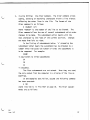
0 <1st number> [<2nd number>] <cr>
Deletes all lines from <lst
number> to <2nd number>, inclusive.
If <2nd number> is omitted,
one 1ine is deleted.
R <lst number>
<2nd number>
<cr>
Replaces the lines from <lst
number> to <2nd number>, inclusive, with input from the console.
After the <cr>, EDIT
displays the number of the
first line to be replaced.
All
input to the next <cr>, replaces
the line.
After the next <cr>,
the number of the next line to
be replaced is displayed.
Typ-
ing a null line causes that line
and the remaining lines in the
range to be deleted.
If <2nd
number> is omitted, one line is
replaced.
Finding a String.
The following commands display the next
occurrence of a character string:
F
<string> <cr>
Finds the next occurrence of
<string> on the current page.
If <string> is found, the line
in which it appears is printed.
If it is not found, an asterisk
is printed and EDIT is ready
for further commands.
The
search begins on the line
immediately after the current
line.
S
<string> <cr>
The same as F, except the
search can extend over page
boundaries.
36
oos
June. 1977
In-Line Editing:
the Alter Command.
The Alter command allows
adding, deleting or modifying characters within a line without
affecting the other lines in the file.
The format of the
Alter command is as follows:
A <number> <cr>
where <number> is the number of the line to be altered.
The
Alter command allows the use of several subcommands which order
changes to be made.
The subcommand action begins with the
next character to the right of the current position.
Changes
are made from left to right.
In the listing of subcommands below, 'n' preceding the
subcommand letter means the subcommand may be preceded by a
number which indicates the number of times the subcommand is
to be repeated.
For example:
3CABC
is equivalent to three subcommands
CA
CB
CC
in sequence.
The Alter subcommands are not echoed.
When they are used,
the only output from the computer is a display of the line as
modified.
In the examples that follow, assume the following command
has been executed:
A 100
where line 100 is in file TEST on page 35.
mands are as follows:
The Alter subcom-
Command
Explanation
n<space>
skips over and prints the next n
characters in the line.
Typing
<space> displays
00100 T
nC<characters>
changes the next n characters in the
line to the specified characters.
Typing 3CHAT displays
00100 THAT
nD
deletes the next n characters.
Typing D displays
00100 THAT
and deletes the following space.
The effect of the subcommand is not
apparent until the next subcommand
is executed.
H<string>
deletes the rest of the line and
inserts the string in its place.
The string is terminated either by
<Escape> or by <cr>.
(On some ter-
minals, Altmode is used rather than
Escape.)
Terminating with <Escape>
allows the Alter command to receive
further subcommands.
Alter mode.
<cr> exits
Typing H'S N0<Escape>
displays
0100 THAT'S NO
I<string>
inserts the string before the next
character.
The string is terminated
either by <Escape> (Altmode on some
terminals) or by <cr>.
Typing
<Escape> allows further subcommands
to be issued.
Alter mode.
Typing <cr> exits
Typing ILINE <cr> dis-
plays
oos
38
June. 1977
0100 THAT'S NO LINE
and exits Alter mode.
To demonstrate the remaining Alter subcommands, the command
^A 100 <cr>
is executed again.
This command reenters Alter mode on the
same line as before and moves the current position to the
beginning of the line.
nK<character>
deletes everything up to (but not
including) the nth occurrence of the
character.
If the character does
not exist, or if there are fewer
than n of them, the subcommand does
nothing.
Typing K0
displays
0100
The effect of the subcommand is not
apparent until the next subcommand
is executed.
R<string>
replaces the next character with the
string.
The string is terminated by
<Escape> or <cr>.
Alter mode.
Typing <cr> exits
Typing RS0ME <space>
<Escape> displays
0100 SOME
nS<character>
skips over and prints all characters
up to, but not including, the nth
occurrence of <character>.
If no
such character exists, or if there
are fewer than n of them, the subcommand does nothing.
Typing SN
displays
0100 SOME LI
X<string>
skips to the end of the line and
inserts the string at that point.
The string is terminated with <Escape>
or <cr>.
<Escape> allows further
COS
J u n e . 1977
39
subcommands to be issued.
Alter mode.
<cr> exits
Typing X , THAT! <cr>
displays
0100
SOME LINE, THAT!
When all of the desired changes have been ordered, Alter
command mode is exited with one of the following subcommands:
<cr>
replaces the existing line with the
line as modified and exits Alter
mode.
Q
exits Alter mode, but makes none of
the ordered changes.
The changes
are lost.
0.
Paging commands.
The amount of memory used by the Text Editor
may be minimized by dividing the file to be edited into pages
and loading one page into memory at a time.
Pages are mani-
pulated by the following commands:
B
Loads the first page of the file
into memory.
Note that after a B
command is issued, the line number
is unpredictable.
An additional
command (.such as P <number>) is
needed to refer to any specific line
on the page.
C
Loads the next page of the file into
memory and saves the current page on
disk.
L
Loads the next page into memory and
deletes the current page
W <number>
Writes the lines currently in memory
from the first to <number> onto disk
as a page.
E.
Miscellaneous commands:
N <increment>
Renumbers all of the lines in the
file.
The difference between suc-
cessive line numbers is <increment>.
oos
June, 1977
The first line number is always
u
100.
P
[<first number>
[<second number>]]
Prints all lines from the <lst
number> to the <2nd number>, inclusive.
If there is no second number,
1 line is printed.
If no line num-
bers are given, the entire current
page is printed.
E <file name>
As the Editor proceeds through the
<device number>
named file making changes, it copies
the modified file into a temporary
file called EDIT.TEM.
When the E
command is executed, the remaining
unmodified lines of the file are
copied into EDIT.TEM.
This file is
then assigned the name of the edited
file.
The first character of the
original file name is changed to $.
This provides a backup file.
U
Any
previous backup file is deleted.
If a file name and device number are
specified in the E command, EDIT
proceeds to edit that file.
Thus,
another file may be edited without
having to reload the Editor.
If
the file and device are not specified,
control is passed to the Monitor.
Q <file name>
Q exits to the monitor without renam-
<device number>
ing any files.
The changes made by
the Editor are ignored.
The Q com-
mand allows the user to abort an
editing session without damaging any
files.
The file name and device num-
ber may be specified as in the E
command to edit another file without
U
having to reload the Editor.
oos
June. 1977
41/(42
Blank)
J
J
J
nntE
W
u
MS
June, 1977
43/(44
Blank)
-t
J
4.
THE ASSEMBLER
The Assembler is a system program that translates programs from
Assembly Language into machine language.
In principle, machine language
can be used to write programs for the computer.
A machine language pro-
gram is one in which the instructions to the computer are represented by
binary numbers
one, two or three bytes long.
The practical problems
of machine language programming, however, make its use virtually impossible for all but the simplest programs.
First, it is difficult to
remember all of the binary machine language codes and enter them into
the computer without error.
Second, machine language requ res the pro-
grammer to remember all of the addresses in the program a;'i refer to
them explicitly.
Finally, if a machine language program does not work
as desired, it is extremely difficult to determine what went wrong.
Assembly language programming is preferable to machine language programming because it avoids all of these difficulties.
Machine instruc-
tions are referred to in Assembly language by unemonics that are descriptive of the operation and that are relatively easy to remember.
Addresses can be specified explicitly, but they can also be referred to
symbolically.
That is, a memory location can be given a label and
referred to subsequently simply by mentioning that label.
Finally,
Assembly language provides the programmer with a complement of error
messages that make the process of debugging much easier than in machine
language programming.
The DOS Assembler translates Assembly Language to machine language
by means of a two step process.
In the first step, the Assembler reads
the Assembly Language program and assigns addresses to all of the symbols.
In the second step, the program is read again and the instructions
are converted to their machine language equivalents.
On this second
pass through the program, the program m y be listed on the terminal or
in a disk file.
If the Assembler detects an error in the
program, the place where the error occurred is marked in the listing
with a letter that indicates the nature of the error.
Once the system disk is mounted in drive 0, the Assembler is run by
typing the following command to the Monitor:
_^ASM <file name> <device> [<device type> <device number-]
where the <file name> i? the name of the disk file that contains the
oos
June, 1977
source program and <device> is the number of the drive where that file
resides.
If a <device type> is specified, an Assembler listing is
written in a file on the specified device.
If the <device type> is TTY,
the listing is printed on the terminal; if the <device type> is FDS, it
is sent to floppy disk.
The name of the listing disk file is the file
name in the ASM command preceded by a percent sign (.%).
The following
message is printed on the terminal upon termination of the assembly:
xxxxx ERRORS DETECTED
where xxxxx is the number (in octal) of errors encountered in the program.
The machine language, object code module that results from the
Assembler's action is written on the same disk as the source code.
The
name of the object code file is the <file name> preceded by an asterisk
(*).
For example, after the following command is executed:
J\SM SOURCE 0 FDS 1
the object code file is named *S0URCE and is written on disk 0.
The
listing of the source program is named %S0URCE and resides on disk 1.
When the assembly and listing are complete, the Assembler prints
ANY MORE ASSEMBLIES?
Typing "Y" causes the Assembler to start over and ask for the new file
name, device number and.listing file parameters.
be assembled without reloading the assembler.
Thus, another file may
Typing N or <cr> exits
the Assembler and returns control to the Monitor.
4-1.
Statements
The fundamental unit of an Assembly Language program is the state-
ment, whose form is as follows:
[label]
<op-code>
<operand> [,<operand>]
[comment]
The label is a tag by which other statements in the program can refer
to this statement.
Not all statements in a program need to be labelled.
Since program execution proceeds normally in order from the lowest memory
location to the highest, statements that need to be executed in normal
sequence need not carry labels.
If, on the other hand, a statement needs
to be executed out of normal order, it must carry a label.
Such out-of-
order execution is called branching and it is particularly important in
programmed decision making and loops.
Labels can also be used to refer
cos
46
June, 1977
to memory locations for storing data.
This use will be discussed more
fully in section 4-2B below.
The op-code is the mnemonic of the machine instruction or Assembler
pseudo-operation to be performed by the statement.
Machine instruction
op-codes are translated by the Assembler into machine language instructions.
Assembler pseudo-ops are not translated, but direct the Assembler
itself to allocate storage areas, set up special addresses, etc.
The op-code is followed by one or more operands, depending upon
the nature of the instruction.
An r^erand is an address - specified in
any one of several manners - where the computer is to find the data to
be operated upon.
In the case of an AOC (add with carry) instruction,
for example, the operand is the address of the location whose contents
are to be added to the accumulator.
In the MOV (above) instruction, the
two operands are the addresses of the location from which a data byte is
to be taken and to which it is to be moved.
Comment may be added to the end of a statement if they are separated
from the rest of the statement by a semicolon.
Comments are ignored by
the Assembler, but they do appear in the Assembler listing and may thus
be used by the programmer for documentation and explanation.
4*2.
Addresses
A program is a series of statements that are stored in memory and
executed either in the order in which they are stored or in sequence
directed by statements in the program itself.
The data operated upon by
the program or used to direct the program's actions is stored in memory
and referred to by the addresses of the locations in which it is stored.
Therefore, addresses are used both to control execution of the program
and to manipulate data.
Much of the versatility of the Assembly Language
programming system in DOS results from the various ways in which addresses
may be represented and modified.
The DOS Assembler recognizes addresses in three major forms;
constants, labels and address expressions.
A.
Constants.
A constant is an address that is stated explicitly
as a number.
For example, the instruction
JMP 23000
oos
June. 1977
47
causes execution to proceed from the location whose address is
23000 decimal.
A constant address may be expressed in octal,
decimal or hexadecimal notation.
1.
Octal address constants are strings of octal characters
(0 - 7) whose first character is zero^
The allowable
range of values is -01777777 to 01777777.
Examples:
0377
01345
017740
2.
Decimal address constants are strings of decimal digits
( 0 - 9 ) without a leading zero.
-65536 to 65536.
The allowed range is
Examples:
255
1024
23000
3.
Hexadecimal address constants have the following form:
X'hhhh'
where h is any hexadecimal digit (0 - 9, A - F).
allowed range is -X'FFFF' to X'FFFF'.
The
Examples:
X'FOOO'
X'2300'
X'OOF'
4.
Character address constants have the following form:
"xx"
where x is any ASCII character except (").
The characters
are translated into binary according to their ASCII codes
and the resulting two-byte quantity makes up the address.
Examp es:
"Al"
"BZ"
B.
Labels.
When a statement is labelled, the label is entered
into the symbol table in the Assembler along with the address
of the statement.
Any subsequent statement can then use the
label to represent that address.
Two types of labels can be
used in the DOS Assembler; names and program points.
oos
48
June. 1977
Names are strings of up to 6 alphanumeric characters.
The first character must be a letter and the subsequent
characters may be letters, numbers or dollar signs.
Examples:
SHIFT
LBL1
A$0UT
The usual use of labels is to refer to a statement by
name.
For example:
SHIFT
RAR
JNC
SHIFT
The operand of the jump instruction tells the computer to
branch back to the RAR (rotate right) instruction if there
is no carry out of the shift.
If there is a carry, execu-
tion proceeds with the next instruction after the jump.
Data bytes can bear labels as well.
ADDEND
AM
ADDEND
DB
255
For example:
These instructions add the contents of location ADDEND to
the accumulator with carry.
In this example, the contents
of ADDEND have the value 255 decimal.
For the purposes of clarity and ease of use, names
should be systematically applied.
That is, they should be
logically related to the statements or data locations they
represent and should be easily distinguishable from other
names in the program.
Sometimes, short branches and Icops require statements to
be labelled, but those labels are not important to the whole
program.
Rather than filling up the symbol table with unique
names, the programmer may prefer to label those statements with
program points.
2.
Program points are special labels with'the following form:
.x
where x is any letter.
A letter may be used any number
of times in a single program.
may be referred to in two ways.
Unlike names, program points
The program point
reference -x refers to the most recently encountered
program point with letter x . . The program point reference
+x refers to the next program point in the program
with the letter x.
Therefore, while any number of
statements may be labelled with the same program point,
a statement may only refer to the two program points
bracketting it in the program.
Address Expressions.
The DOS Assembler allows addresses to be
specified relative to other addresses.
For example, to refer
to the fourth location after the location labelled LOC, the
following expression can be used:
LOC+4
Expressions of this form are called address expressions.
Address expressions may be comprised of any of the following:
Name
Constant
Program point reference
Address expression + constant
The sixteen bit values of the names, constants, program point
references and address expression., are combined and truncated
to 16 bits to form the value of the final address expression.
oos
J u n e , 1977
Example:
SHIFT+5
+A-010
LOC+X'F'
Special Addresses.
The DOS Assembler allows certain addresses
to be referred to directly with special notation.
*
indicates the present contents of the location counter.
That is, * refers to the address of the current instruction or the current data address.
Registers may be addressed symbolically by name.
There-
fore, such instructions as
MOV
H,A
are interpreted to refer to the correct registers.
Addressing Modes.
The addresses of statements or data loca-
tions are specified in one of five different modes.
The DOS
Assembler addressing modes are Absolute, Relative, Common,
Data and External.
Absolute addresses are the actual hardware addresses of
the designated locations.
Address constants in themselves
(not in address expressions) refer to absolute mode addresses.
If an absolute mode address is specified, all of the other
addresses in the program must be relocated to fit it.
Relative addresses are relocated by the action of the
Linking Loader.
Unless otherwise specified, all symbolic
addresses (names, program points, address expressions) are in
Relative mode.
To calculate a Relative mode address, the
Assembler calculates a displacement which the Linking Loader
adds to a relocation base address when the program is loaded.
In this way, the loader can load the program anywhere in
memory and all the addresses bear the correct relation to
each other.
An External mode address is one that refers to a location
in another program.
A name must be mentioned in an EXT state-
ment before it can be used as an External mode address.
External addresses allow a program to use routines or data in
another program.
Data and Common mode addresses refer to separate blocks
of memory locations that may or may not be contiguous with the
programs which make the references.
Data mode addresses are
so designated by being mentioned in a DAT statement.
mode items are designated by CMN statements.
Common
The difference
between Common and Data addresses is that Data addresses may
only be referenced by the program in which they are defined,
whereas Common mode addresses are available to any program.
In addition, several Common blocks can exist simultaneously and
be referred to by name.
In an address expression, the constituent addresses may
have different modes.
Any mode expression combined with an
Absolute mode address has the mode of the expression.
The
difference-of two expressions of the same mode is of Absolute
mode.
4-3.
Op-Codes
Op-codes are of two types.
One type, the machine codes, are the
mnemonic expressions of the 8080 instructions.
These op-codes and their
associated operands are discussed in section A , below, which is reprinted
from the Intel 8080 Microcomputer System Users' Manual.
The Assembler
can use any address expression to derive the required address for direct
or immediate addressing instructions.
Register instructions can use any
address expression as long as its value is the address of a register
( 0 - 7 absolute).
Before a register indirect mode instruction may be
used, the register pair must be loaded with an address.
Any address
expression can be used to supply that address.
oos
June, 1977
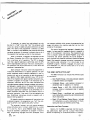
A computer, no matter how sophisticated, can only
do what it is "totd" to do. One "teils" the computer what
to do via a series of coded instructions referred to as a Program. The reaim of the programmer is referred to as Software, in contrast to the Hardware that comprises the actua)
computer equipment. A computer's software refers to all of
the programs that have been written for that computer.
When a computer is designed, the engineers provide
the Centra) Processing Unit (CPU) with the ability to perform a particular set of operations. The CPU is designed
such that a specific operation is performed when the CPU
control logic decodes a particular instruction. Consequent^,
the operations that can be performed by a CPU define the
computer's instruction Set.
Each computer instruction allows the programmer to
initiate the performance of a specific operation. At) computers imptement certain arithmetic operations in their instruction set, such as an instruction to add the contents of
two registers. Often logica) operations (e.g.. OR the contents of two registers) and register operate instructions (e.g.,
increment a register) are inciuded in the instruction set. A
computer's instruction set will aiso have instructions that
move data between registers, between a register and memory,
and between a register and an I/O device. Most instruction
sets also provide Conditions) Instructions. A conditional
instruction specifies an operation to be performed only if
certain conditions have been met; for example, jump to a
particuiar instruction if the result of the last operation was
zero. Conditional instructions provide a program with a
decision-making capability.
By logically organizing a sequence of instructions into
a coherent program, the programmer can "tell" the computer to perform a very specific and useful function.
The computer, however, can only execute programs
whose instructions are in a binary coded form (i.e., a series
of 1's and O's), that is called Machine Code. Because it
would be extremely cumbersome to program in machine
code, programming languages have been deveioped. There
OOS
June, 1977
are programs available which convert the programming Ian-!
guage instructions into machine code that can be interpreted by the processor.
One type of programming language is Assembty Language. A unique assembly language mnemonic is assigned to
each of the computer's instructions. The programmer can
write a program (called the Source Program) using these
mnemonics and certain operands; the source program is
then converted into machine instructions (caited the Object
Code). Each assembly language instruction is converted into
one machine code instruction (1 or more bytes) by an
Assembier program. Assembty languages are usually machine dependent (i.e., they are usuaiiy able to run on oniy
onetypeofcomputer).
THE 8080 t N S T R U C H O N SET
The S080 instruction set includes five different types
ofinstructions:
*
Data Transfer Group—move data between registers
or between memory and registers
*
Arithmetic Group - add, subtract, increment or
decrement data in registers or in memory
.
Logica) Group - AND, O R , EXCLUS)VE-OR,
compare, rotate or complement data in registers
orinmemory
*
Branch Group - conditiona) and unconditiona)
jump instructions, subroutine ca)) instructions and
return instructions
*
Stack, )/0 and Machine Contro) Group — inciudes
I/O instructions, as wei) as instructions for maintaining the stack and interna) contro) flags.
tnstruction and Data Formats:
Memory for the 8080 is organized into 8-bit quantities, catted Bytes. Each byte has a unique 16-bit binary
address corresponding to its sequentiat position in memory.
53
The 8080 can directly address up to 65,536 bytes of memory, which may consist of both read-oniy memory (ROM)
etements and random-access memory [RAM) etements (read/
write memory).
Data in the 8080 is stored in the form of 8-bit binary
address where the data is located (the
high-order bits of the address are in the
first register of the pair, the low-order
bitsinthesecond).
*
integers:
DATA WORD
D?
Dg
Og
O4
D3
O2
Di
Do
LSB
MSB
When a register or data word contains a binary number, it is necessary to estabfish the order in which the bits
of the number are written. !n the Intei 8080, B)T 0 is referred to as the Least Significant Bit (LSB), and B)T 7 (of
an 8 bit number) is referred to as the Most Significant Bit
(MSB).
The 8080 program instructions may be one, two or
three bytes in length. Multiple byte instructions must be
stored in successive memory locations; the address of the
first byte is always used as the address of the instructions.
The exact instruction format win depend on the particuiar
operation to be executed.
Immediate — The instruction contains the data itself. This is either an 8-bit quantity or a
16-bit quantity (least significant byte first,
most significant byte second).
Unless directed by an interrupt or branch instruction,
the execution of instructions proceeds through consecutively increasing memory locations. A branch instruction
can specify the address of the next instruction to be executed in one of two ways:
*
Direct—The branch instruction contains the address of the next instruction to be exe. cuted. (Except for the 'RST' instruction,
byte 2 contains the low-order address and
byte 3 the high-order address.)
*
Register indirect - T h e branch instructionindicates a register-pair which contains the
address of the next instruction to be executed. (The high-order bits of the address
are in the first register of the pair, the
low-order bits in the second.)
Single Byte Instructions
D?
Do
Op Code
Two-Byte Instructions
Byte One
D?
Do
Op Code
Byte Two
0?
Do
Data or
Address
Three-Byte Instructions
Byte One
D?
Do
Op Code
Byte Two
D?
Do
Byte Three
D?
Do
Data
or
Address
The RST instruction is a specia) one-byte cai! instruction (usuaity used during interrupt sequences). RST inciudes a three-bit field; program contro) is transferred to
the instruction whose address is eight times the contents
of this three-bitfield.
Condition Flags:
There are five condition flags associated with the execution of instructions on the 8080. They are Zero, Sign,
Parity, Carry, and Auxiliary Carry, and are each represented
by a 1-bit register in the CPU. A flag is "set" by forcing the
bit to 1; "reset" by forcing the bit to 0.
Untess indicated otherwise, when an instruction affects a flag, it affects it in the foilowing manner:
Zero:
If the result of an instruction has the
value 0 , t h i s f t a g is set; otherwise i t i s
reset.
Sign:
Ifthemostsignificantbitoftheresultof
the operation has the value 1, this fiag is
set; otherwise it is reset.
Parity:
tf the modulo 2 sum of the bits of the result of the operation is 0, (i.e., if the
result has even parity), this fiag is set;
otherwise it is reset (i.e., if the result has
odd parity).
Carry:
If the instruction resuited
i a carr/
(from addition), or a borrow sfrom subtraction or a comparison) out of the highorderbit,thisf)agisset;otherwiseitis
reset.
OOS
Addressing Modes:
Often the data that is to be operated on is stored in
memory. When muiti-byte numeric data is used, the data,
like instructions, is stored in successive memory locations,
with the least significant byte first, foltowed by increasingly
significant bytes. The 8080 has four different modes for
addressing data stored in memory or in registers:
*
Direct - Bytes 2 and 3 of the instruction contain
the exact memory address of the data
item (the tow-order bits of the address are
in byte 2, the high-order bits in byte 3).
*
Register — The instruction specifies the register or
register-pair in which the data is located.
*
Register Indirect - The instruction specifies a register-pair which contains the memory
54
June. 1977
Auxiliary Carry: tf the instruction caused a carry out
rh
The first (high-order) register of a designated
rt
The second (tow-order)' register of a desig-
ofbit3andintobit4oftheresuiting
vatue, the auxitiary carry is set; otherwise
register pair.
it is reset. This flag is affected by singie
precision additions, subtractions, increments, decrements, comparisons, and tog-
nated register pair.
PC
16-bit program counter register (PCH and
PCL are used to refer to the high-order and
icai operations, but is principatty used
low-order 8 bits respectivety).
with additions and increments preceding
a DAA
(Decima) Adjust
Accumutator)
SP
16-bit stack pointer register (SPH and SPL
are used to refer to the high-order and low-
instruction.
order 8 bits respectivety).
r^
Symbots and Abbreviations:
Bit m of the register r (bits are number 7
through 0 from left to right).
The fottowing symbois and abbreviations are used in
Z,S,P,CY,AC
the subsequent description of the 8080 instructions:
The condition ftags:
Zero,
SYMBOLS
MEANtNG
accumuiator
Register A
Parity,
addr
16-bit address quantity
Carry,
data
8-bit data quantity
Sign,
and Auxitiary Carry, respectivety.
(
)
The contents of the memory location or reg-
data 16
16-bit data quantity
byte 2
The second byte of the instruction
byte 3
The third byte of the instruction
port
8-bit address of an )/0 device
r,r1,r2
One of the registers A,B,C,D,E,H,L
DD0,SSS
The bit pattern designating one of the registers A,B,C,D,E,H,L (DDD=destination, SSS=
+
Addition
source):
—
Two's comptement subtraction
isters enctosed in the parentheses.
—
"ts transferred t o "
A
Logica) ANO
V
ExctusiveOR
V
InctusiveOR
*
OOO or SSS
rp
111
A
000
3
"tsexchangedwith"
The one's comptement (e.g., (A))
001
C
n
010
D
NNN
011
E
100
H
101
L
The restart number 0 through 7
The binary representation 000 through 111
for restart number 0 through 7 respectivety.
Oneoftheregisterpairs:
Description Format:
8 represents the B,C pair with 8 as the high-
The foitowing pages provide a detailed description of
order register and C as the tow-order register;
the instruction set of the 8080. Each instruction is de-
0 represents the D,E pair with D as the high-
scribed in the foXowing manner:
order register and E as the low-order register;
H represents the H,L pair with H as the highorder register and L as the low-order register;
SP
represents
the
16-bit
stack
pointer
The bit pattern designating one of the regis-
00S
June. 1377
assembter format, consisting of
the instruction mnemonic and operand fietds, is
printed in BOLDFACE on the left side of the first
line.
thesis on the right side of the first line.
3. The next line(s) contain a symbotic description
ter pairs 3,0,H,SP:
RP
1. The MAC 80
2. The name of the instruction is enctosed in paren-
register.
RP
Muitiptication
REGiSTER NAME
REG)STERPA)R
00
8-C
01
D-E
10
H-L
11
SP
of the operation of the instruction.
4. This is fottowed by a narative description of the
operation of the instruction.
5. The fottowing line(s) contain the binary fietds and
patterns that comprise the machine instruction.
55
The !ast four tines contain incidents) information
MV! r, data
(Move immediate)
about the execution of the instruction. The num-
(r)
ber of machine cycies and- states required to exe-
The content of byte 2 of the instruction is moved to
cute the instruction are tisted first. )f the instruc-
register r.
(byte 2)
tion has two possibie execution times, as in a
Conditiona) J u m p , both times wilt be listed, separated by a siash. Next, any significant data addata
dressing modes (see Page 4-2) are listed. The last
tine lists any of the five Piags that are affected by
the execution of the instruction.
Cycles:
2
States:
7
Addressing:
Ftags:
immediate
none
Data Transfer Group:
This group of instructions transfers data to and from
registers and memory. Condition flags are not affected by
any instruction in this group.
MOVr1,r2
(Move Register)
(r1) -*— (r2)
The content of register r2 is moved to register r1.
MV) M, data
(Move to memory immediate)
«H)(L))-*-(byte2)
The content of byte 2 of the instruction is moved to
the memory location whose address is in registers H
and L.
Cycles:
States:
Addressing:
Ftags:
MOV r, M
1
5
register
data
none
Cycles:
3
States:
10
Addressing:
(Move from memory)
Ftags:
immed./reg. indirect
none
(r) -*— ((H) (L))
The content of the memory tocation, whose address
is in registers H and L, is moved to register r.
Cyctes:
2
States:
7
Addressing:
Ftags:
LX) rp, data 16
reg. indirect
(rh)^—
none
(r!)
(Load register pair immediate)
(byte 3),
(byte 2)
Byte 3 of the instruction is moved into the high-order
register (rh) of the register pair rp. Byte 2 of the instruction is moved into the tow-order register (rt) of
MOV M, r
(Move to memory)
the register pair rp.
((H) (L)) -*— (r)
The content of register r is moved to the memory location whose address is in registers H and L.
R
low-order data
high-order data
Cyctes:
2
Cyctes:
3
States:
7
States:
10
Addressing:
Ftags:
reg. indirect
none
Addressing:
Ftags:
immediate
none
^
June, 1977 ^
LDA addr
SHLD addr
(Load Accumuiator direct)
(Store H and L direct)
{A)-*-((byte3)(byte2))
((byte3)(byte2)) —
The cqntent of the memory location, whose address
« b y t e 3 ) ( b y t e 2 ) + 1 ) - * — (H)
(L)
is specified in byte 2 and byte 3 of the instruction, is
The content of register L is moved to the memory lo-
moved to register A.
cation whose address is specified in byte 2 and byte
3. The content of register H is moved to the succeed-
1
ing memory iocation.
low-order addr
high-order addr
low-order addr
Cyctes:
States:
Addressing:
Flags:
4
high-order addr
13
direct
Cycies:
none
States:
Addressing:
Flags:
LDAX rp
(A)
STA addr
16
direct
none
(Load accumuiator indirect)
((rp))
The content of the memory location, whose address
(Store Accumulator direct)
«byte3)(byte2))
5
is in the register pair rp, is moved to register A. Note:
(A)
The content of the accumuiator is moved to the
only register pairs rp^B (registers B and C) or rp=*D
memory location whose addressis specified in byte
(registers D and E) may be specified.
2 and byte 3 of the instruction.
low-order addr
States:
Addressing:
Fiags:
2
States:
7
Addressing:
high-order addr
Cycies:
Cycles:
Fiags:
4
STAX rp
13
reg. indirect
none
(Store accumulator indirect)
((rp)) -*— (A)
direct
The content of register A is moved to the memory lo-
none
cation whose address is in the register pair rp. Note:
oniy register pairs rp=8 (registers B and C) or rp-0
(registers D and E) may be specified.
0
LHLD addr
(L)^—
(Load H and L direct)
((byte3)(byte2))
( H ) ^ - ( ( b y t e 3 ) ( b y t e 2 ) + 1)
Cyctes:
2
States:
7
Addressing:
The content of the memoty location, whose address
Flags:
reg. indirect
none
is specified in byte 2 and byte 3 of the instruction, is
moved to register L. The content of the memory location at the succeeding address is moved to register H.
XCHG
(L)
1
(Exchange H and L with D and E)
(H)^-(D)
(E)
The contents of registers H and L are exchanged with
the contents of registers D and E.
high-order addr
Cyctes:
5
Cycies:
States:
16
States:
Addressing:
oos
June. 1977
Fiags:
direct
none
Addressing:
Flans:
1
4
register
none
57
Arithmetic Group:
This group of instructions performs arithmetic operations on data in registers and memory.
Untess indicated otherwise, at) instructions in this
group affect the Zero, Sign, Parity, Carry, and Auxitiary
Carry ftags according to the standard ruies.
ADC r
(Add Register with carry)
' (A)
(A) + (r) + (CY)
The content of register r and the content of the carry
bit are added to the content of the accumuiator. The
resuit is piaced in the accumuiator.
AO -subtraction operations are performed via two's
compiement arithmetic and set the carry fiag to one to indicate a borrow and dear it to indicate no borrow.
ADD r
(Add Register)
(A) -*— (A) + (r)
The content of register r is added to the content of the
accumulator. The result is placed in the accumuiator.
Cycies:
States:
Addressing:
Flags:
Cycies:
States:
Addressing:
Fiags:
Cycles:
States:
Addressing:
Flags:
AC) data
The content of the memory location whose address
is contained in the H and L registers is added to the
content of the accumulator. The resuit is ptaced in
the accumulator.
Cyctes:
States:
Addressing:
Ftags:
2
7
reg. indirect
Z,S,P,CY,AC
(Add immediate with carry)
data
Cycles:
States:
Addressing:
Z,S,P,CY,AC
2
7
immediate
Z.S.P.CY.AC
(Add immediate)
( A ) ^ — (A) + (byte2)
The content of the second byte of the instruction is
added to the content of the accumuiator. The resuit
is otaced in the accumulator.
Cycles:
States:
Addressing:
Flags:
58
2
7
reg. indirect
(A) -*— (A) + (byte 2) + (CY)
The content of the second byte of the instruction and
the content of the CY flag are added to the contents
of the accumulator. The resutt is ptaced in the
accumuiator.
Ftags:
AD) data
4
register
Z,S,P,CY,AC
ADC M
(Add memory with carry)
(A)
(A) + ((H) (L)) + (CY)
The content of the memory location whose address is
contained in the H and L registers and the content of
the CY flag are added to the accumulator. The result
is placed in the accumulator.
1
4
register
Z,S,P,CY,AC
ADD M
(Add memory)
( A ) - * - ( A ) + ((H)(L))
1
2
7
immediate
Z.S.P.CY.AC
SUB r
(A)
(Subtract Register)
(A) - (r)
The content of register r is subtracted from the content of the accumuiator. The resutt is ptaced in the
accumuiator.
Cycies:
States:
Addressing:
Flags:
1
4
register
Z,S,P,CY,AC
OOS
June. 1977
SUB M
(Subtract memory)
SBtdata
.
( A ) - * - ( A ) - ( ( H ) (L))
(Subtractimmediatewithborrow)
(A) -*— (A) - (byte 2) - (CY)
The content of the memory location whose address is
The contents of the second byte of the instruction
contained in the H and L registers is subtracted from
and the contents of the CY flag are both subtracted
the content of the accumuiator. The resuit is placed
from the accumulator. The result is placed in the
in the accumuiator.
accumulator.
data
Cycies:
States:
Addressing:
Flags:
reg. indirect
Z,S,P,CY,AC
Cyctes:
2
States:
7
Addressing:
Flags:
SUtdata
immediate
Z.S.P.CY.AC
(Subtractimmediate)
(A) -*— (A) - (byte 2)
The content of the second byte of the instruction is
iNR r
(Increment Register)
subtracted from the content of the accumuiator. The
resutt is ptaced in the accumuiator.
1
1
(r)^—
(r) + 1
The content of register r is incremented by one.
Note: Att condition ftags except CY are affected.
1
data
Cyctes:
2
Cycles:
States:
7
States:
Addressing:
Flags:
S8B r
Ftags:
Z.S.P.CY.AC
(Subtract Register with borrow)
(A)
Addressing:
immediate
(A) - (r) - (CY)
tNRM
1
5
register
Z,S,P,AC
(Increment memory)
((H) (L)) -*— ((H) (L)) + 1
The content of register r and the content of the CY
The content of the memory location whose address
ftag are both subtracted from the accumuiator. The
is contained in the H and L. registers is incremented
resutt is ptaced in the accumuiator.
by one. Note: At) condition ftags except CY are
affected.
Cycies:
States:
Addressing:
Ftags:
1
4
Cyctes:
register
States:
Z,S,P,CY,AC
Addressing:
Flags:
SBB M
3
10
reg. indirect
Z,S,P,AC
(Subtract memory with borrow)
(A) -*— (A) - ( ( H ) (L)) - (CY)
The content of the memory location whose address is
OCR r
(Decrement Register)
contained in the H and L registers and the content of
(r)
the CY ftag are both subtracted from the accumuia-
The content of register r is decremented by one.
(r) - 1
tor. The resutt is ptaced in the accumuiator.
Note: Ait condition ftags except CY are affected.
T V !
Cyctes:
Cyctes:
States:
Addressing:
OOS'
J u n e . 1977
Ftags:
States:
reg. indirect
Z.S.P.CY.AC
Addressing:
Ftags:
1
1
5
register
Z,S.P.AC
59
OCR M
(Decrement memory)
((H) (L)) —
DAA
(Decimat Adjust Accumulator)
The eight-bit number in the accumulator is adjusted
((H) (L)) - 1
The content of the memory location whose address is
to form two four-bit Binary-Coded-Decimat digits by
contained in the H and L registers is decremented by
the fotlowing process:
one. Note: Ait condition fiags except C Y are affected.
1.
If the value of the least significant 4 bits of the
accumuiator is greater than 9 or if the AC fiag
1
1
is set, 6 is added to the accumutator.
2.
tf the vaiue of the most significant 4 bits of the
Cyctes:
3
States:
10
accumulator is now greater than 9, or if the CY
reg. indirect
ftag is set, 6 is added to the most significant 4
Z,S,P,AC
bits of the accumutator.
Addressing:
Fiags:
NOTE:
tNXrp
Att ftags are affected.
(tncrement register pair)
(rh) (rt) —
(rh) (rt) + 1
The content of the register pair rp is incremented by
one. Note: No condition ftags are affected.
Cyctes:
1
States:
5
Addressing:
Flags:
Cycles:
1
States:
4
Ftags:
Z,S,P,CY,AC
Logica) Group:
This group of instructions performs logicai (Boolean)
register
operations on data in registers and memory and on condi-
none
tion ftags.
Untess indicated otherwise, att instructions in this
group affect the Zero, Sign, Parity, Auxiliary Carry, and
Carry flags according to the standard rules.
DCX rp
(Decrement register pair)
(rh) (rt) -*— (rh) (rl) - 1
ANA r
(AND Register)
The content of the register pair rp is decremented by
(A)
one. Note: No condition ftags are affected.
The content of register r is togicatty anded with the
(A) A ( r )
content of the accumutator. The resutt is ptaced in
the accumutator. The CY ftag is cieared.
Cyctes:
States:
Addressing:
Fiags:
1
5
register
Cycies:
none
States:
Addressing:
Flags:
DAO rp
(Add register pair to H and L)
(H) (L) -*— (H) (L) + (rh) (rl)
The content of the register pair rp is added to the
content of the register p a i r H a n d L . T h e r e s u i t i s
ptaced in the register pair H and L. Note: Onty the
CY ftag is affected. It is set if there is a carry out of
1
4
register
Z,S,P,CY,AC
ANA M
(AND memory)
(A) —
(A) A ((H) (L))
The contents of the memory location whose address
is contained in the H and L registers is iogicatly anded
with the content of theaccumutator.Theresuit is
ptaced in the accumutator. The CY ftag is cieared.
the doubte precision add; otherwise it is reset.
Cyctes:
3
Cyctes:
2
States:
10
States:
7
Addressing:
Ftags:
60
register
CY
Addressing:
Ftaqs:
reg.indirect
Z.S.P.CY.AC
00S
June. 1977
AN) data
(AND immediate)
ORA r
(A) -*— (A) A (byte 2)
(OR Register)
(A) - * - (A) V (r)
The content of the second byte of the instruction is
The content of register r is inciusive-OR'd with the
logicatty anded with the contents of the accumuiator.
content of the accumutator. The resutt is piaced in
The resuit is piaced in the accumuiator. The CY and
the accumutator. The CY and AC ftags are cteared.
AC ftags are cteared.
1
, 1
Cyctes: - 1
data
2
States:
7
Addressing:
Flags:
XRAr
States:
Cycies:
immediate
Z.S.P.CY.AC
(Exclusive OR Register)
(A) -*— (A) V (r)
The content of register r is exciusive-or'd with the
content of the accumuiator. The resuit is placed in
the accumuiator. The CY and AC ftags are cieared.
Cycies:
States:
Addressing:
Ftags:
(A)
register
Ftags:
ORAM
Z.S.P.CY.AC
(OR memory)
(A) —
(A) V ((H) (L))
The content of the memory location whose address is
contained in the H and L registers is inciusive-OR'd
with the content of t h e a c c u m u i a t o r . T h e r e s u i t i s
ptaced in the accumutator. The CY and AC ftags are
cteared.
1
4
Cyctes:
2
States:
7
Addressing:
register
reg. indirect
Ftags:
Z,S.P,CY,AC
ORtdata
X R A IV)
4
Addressing:
(Exclusive OR Memory)
Z.S.P.CY.AC
(ORtmmediate)
(A) -*— (A) V (byte 2)
(A) V ((H) (L))
The content of the second byte of the instruction is
The content of the memory location whose address
inciusive-OR'd with the content of the accumutator.
is. contained in the H and L registers is exctusive-OR'd
The resutt is placed in the accumulator. The CY and
with the content of the accumuiator. The result is
AC ftags are cteared.
placed in the accumulator. The CY and AC ftags are
m
cteared.
*
data
Cycies:
2
Cycies:
2
States:
7
States:
7
Addressing:
Fiags:
XRtdata
(A)
Addressing:
reg. indirect
(Exciusive OR immediate)
(A) V (byte 2)
The content of the second byte of the instruction is
exclusive-OR'd with the content of the accumuiator.
The result is piaced in the accumulator. The CY and
AC ftags are cteared.
immediate
Ftags:
Z.S,P,CY,AC
CMP r
Z.S.P.CY.AC
(Compare Register)
(A) - (r)
The content of register r is subtracted from the accumuiator. The accumutator remains unchanged. The
condition ftags are set as a resutt of the subtraction.
The Z ftag is sat to 1 if (A) = (r). The CY ftag is set to
1 if ( A M ( r ) .
data
Cycies:
2
Cyctes:
States:
7
States:
Addressing:
OOS
June. 1977
Ftags:
immediate
Z.S.P.CY.AC
Addressing:
Ftags:
1
4
register
Z.S.P.CY.AC
61
CMP M
(Compare memory)
RRC
(Rotateright)
(A) - ((H) ( U )
(A,J -*— (An-1) ;
The content of the memory location whose address
(CY)^-
is contained in the H and L registers is subtracted
The content of the accumutator is rotated right one
(Ay) - * - (Ag)
(Ag)
from the accumutator. The accumutator remains un-
position. The high order bit and the CY ftag are both
changed. The condition ftags are set as a resutt of the
set to the. vatue shifted out of the low order bit qpsi-
s u b t r a c t i o n . T h e Z f t a g is set t o 1 if (A) = ( ( H ) ( L ) ) .
tion. Onty the CY ftag is affected.
The CY ftag is set to 1 if (A) < ((H) ( U ) .
1
States:
4
Fiags:
Cyctes:
States:
Addressing:
Cyctes:
CY
reg. indirect
Flags:
Z,S,P,CY,AC
RAL
(Rotate left through carry)
(An+1)
-*-(An);(CY)^—
(A?)
(AQ) -*— (CY)
The content of the accumutator is rotated left one
position through the CY ftag. The low order bit is set
equat to the CY ftag and the CY ftag is set to the
vatue shifted out of the high order bit. Onty the CY
CP) data
ftag is affected.
(Compare immediate)
(A) - (byte 2)
The content of the second byte of the instruction is
subtracted from the accumuiator. The condition flags
Cyctes:
are set by the resutt of the subtraction. The Z flag is
States:
set to 1 if (A) = (byte 2). The CY ftag is set to 1 if
Ftags:
(A) < (byte 2).
RAR
4
CY
(Rotate right through carry)
(A,,) —
data
1
(An+1) ; (CY)
(AQ)
(Ay) -*— (CY)
The content of the accumutator is rotated right one
Cyctes:
position through the CY ftag. The high order bit is set
States:
to the CY ftag and the CY ftag is set to the vaiue
Addressing:
Flags:
immediate
shifted out of the low order bit. Oniy the CY ftag is
Z,S,P.CY,AC
affected.
Cyctes:
1
States:
4
Fiags:
RLC
CY
(Rotate left)
(An+1)^— (An);(Ao)-^-(Ay)
CMA
(CY) -*— (Ay)
(Comptement accumutator)
The content of the accumuiator is rotated left one
(A) —
position. The low order bit and the CY ftag are both
The contents of the accumulator are compiemented
(A)
set to the vatue shifted out of the high order bit posi-
(zero bits become 1, one bits become 0). No ftags are
tion. Onty the CY ftag is affected.
affected.
1
Cycies:
1
Cyctes:
1
States:
4
States:
4
Fiaos:
62
CY
Flaqs:
none
00S
J u n e . 1977
CMC
.
dress is specified in byte 3 and byte 2 of the current
(Compiement carry)
(CY)
instruction.
(CY)
The CY ftag is comptemented. No other ftags are
affected.
1
tow-order addr
1
high-order addr
Cycies:
States:
Ftags:
STC
1
4
CY
Cyctes:
States:
Addressing:
Ftags:
(Set carry)
(CY) —
1
The CY ftag is set to 1. No other ftags are affected.
0 !
o
1 *!
'
1
Cyctes:
States:
Ftags:
'
0
!
1
'
1
!
1
1
4
CY
Jcondition addr
tf (CCC).
3
10
immediate
none
(Conditionat jump)
(PC) -*— (byte 3) (byte 2)
If the specified condition is true, control is transferred to the instruction whose address is specified in
byte 3 and byte 2 of the current instruction; otherwise, controt continues sequentiaity.
low-order addr
high-order addr
Cyctes:
States:
Addressing:
Branch Group:
Ftags:
3
10
immediate
none
This group of instructions atter norma) sequentiat
program ftow.
Condition ftags are not affected by any instruction
in this group.
The two types of branch instructions are unconditiona) and conditional Unconditiona) transfers simpty perform the specified operation on register PC (the program
counter). Conditionat transfers examine the status of one of
the four processor ftags to determine if the specified branch
is to be executed. The conditions that may be specified are
as foiiows:
COND)T)ON
NZ
Z
NC
C
PO
PE
P
M
CCC
- not zero (Z 0)
- zero ( Z = 1)
- no carry (CY = 0)
- carry (CY - 1)
- p a r i t y odd (P = 0)
- parity even (P = 1)
000
- ptus (S - 0)
- minus (S = 1)
110
111
JMP addr
001
010
011
100
(Jump)
(PC) -*— (byte 3) (byte 2)
oos
1
101
Controt is transferred to the instruction whose ad-
June. 1977
CALL addr
(Cait)
((SP) - 1)
(PCH)
((SP) - 2 )
(PCL)
(SP) —
(SP) - 2
(PC) -+— (byte 3) (byte 2)
The high-order eight bits of the next instruction address are moved to the memory location whose
address is one less than the content of register SP.
The low-order eight bits of the next instruction address are moved to the memory location whose
address is two less than the content of register SP.
The content of register SP is decremented by 2. Control is transferred to the instruction whose address is
specified in byte 3 and byte 2 of the current
instruction.
high-order addr
Cycles:
States:
Addressing:
Ftags:
5
17
immediate/reg. indirect
none
63
Ccondition addr
(Condition cait)
RSTn
(Restart)
((SP) - 1)
)f (CCC),
((SP) - 1 )
((SP) - 2 ) —
(PCH)
( ( S P ) - 2 ) - < — (PCL)
(PCH)
(SP)
(PCL)
(SP) - 2
(PC) -*— 8 - ( N N N )
(SP)
(SP) - 2
(PC)
(byte 3) (byte 2)
The high-order eight bits of the next instruction ad-
if the specified condition is true, the actions specified
dress are moved
in the CALL instruction (see above) are performed;
address is one less than the content of register SP.
otherwise, contro) continues sequentiatty.
The low-order eight bits of the next instruction ad-
to the memory location whose
dress are moved
to the memory location whose
address is two less than the content of register SP.
The content of register SP is decremented by two.
low-order addr
Controt is transferred to the instruction whose address is eight times the content of NNN.
high-order addrCycies:
States:
Addressing:
Ftags:
3/5
N
N
11/17
immediate/reg. indirect
none
N
Cycles:
3
States:
11
Addressing:
reg. indirect
Flags:
RET
none
(Return)
(PCL)
((SP));
(PCH)
((SP) + 1);
15 14 13 12 11 10
0
(SP) -*— (SP) + 2;
0
The content of the memory location whose address
0
0
0
0
9
8
0
7
0
6
0
5
0
4
N
3
N
N
2
0
1
0
0
0
Program Counter After Restart
is specified in register SP is moved to the low-order
eight bits of register PC. The content of the memory
location whose address is one more than the content
of register SP is moved to the high-order eight bits of
register PC. The content of register SP is incremented
by 2.
PCHL
Cyctes:
States:
Addressing:
Ftags:
(Jump H and L indirect - move H and L to PC)
(PCH) -*— (H)
3
10
(PCL) —
reg. indirect
The content of register H is moved to the high-order
(L)
none
eight bits of register PC. The content of register L is
moved to the low-order eight bits of register PC.
Rcondition
(Conditionat return)
Cycles:
tf (CCC),
States:
(PCL)-*—((SP))
Addressing:
(PCH)-*— ((SP) + 1)
Fiags:
(SP) -*— (SP) + 2
1
5
register
none
tf the specified condition is true, the actions specified
in the RET instruction (see above) are performed;
otherwise, controt continues sequentiatty.
0
Cycies:
1/3
States:
5/11
Addressing:
Flaqs:
reg. indirect
none
COS
FLAG W O R D
Stack, )/0, and Machine Controi Group:
This group of instructions performs I/O, manipulates
D?
Dg
Dg
D4
D3
Da
O1
Do
1
CY
the Stack, and aiters interna) controt ftags.
AC
Untess otherwise specified, condition ftags are not
affected by any instructions in this group.
PUSH rp
(Push)
((SP) - 1)
((SP) - 2)
(SP)
POP rp
(Pop)
(rh)
(rt) -*—((SP))
(rt)
(rh)
((SP) + 1)
(SP) -*— (SP) + 2
(SP) - 2
The content of the high-order register of register pair
The content of the memory location, whose address
rp is moved to the memory tocation whose address is
is specified by the content of register SP, is moved to
one less than the content of register SP. The content
the low-order register of register pair rp. The content
of the tow-order register of register pair rp is moved
of the memory location, whose address is one more
to the memory location whose address is two less
than the content of register SP, is moved to the high-
than the content of register SP. The content of reg-
order register of register pair rp. The content of reg-
ister SP is decremented by 2. Note: Register pair
ister SP is incremented by 2. Note: Register pair
rp =* SP may not be specified.
rp =* SP may not be specified.
Cyctes:
3
Cyctes:
States:
11
States:
Addressing:
Ftags:
reg. indirect
Addressing:
none
Ftags:
POP PSW
PUSH PSW
(A)
((SP) - 2)o - * - (CY) , ((SP) - 2) 1 -*— 1
((SP)-2)2—-(P),
((SP)-2)3-^-0
((SP) - 2)4 -*— (AC) , ((SP) ((SP) - 2)g —
(SP) —
(Z) ,
2)5
((SP) - 2)y
10
reg. indirect
none
(Pop processor status word)
«SP))Q
(P)
((SP))2
(AC) — ((SP))4
(Z)
((SP))g
(S)
((SP))?
(A) -*— ((SP) + 1)
(SP)
(SP) + 2
(CY)-*—
(Push processor status word)
((SP) - 1 )
3
0
(S)
(SP) - 2
The content of register A is moved to the memory
The content of the memory location whose address
location whose address is one less than register SP.
is specified by the content of register SP is used to
The contents of the condition ftags are assembled
restore the condition ftags. The content of the mem-
into a processor status word and the word is moved
ory location whose address is one more than the
to the memory location whose address is two iess
content of register SP is moved to register A. The
than the content of register SP. The content of reg-
content of register SP is incremented by 2.
isterSPisdecrementedbytwo.
Cycies:
States:
Cyctes:
Addressing:
States:
Addressing!
Flags:
reg.indirect
Flags:
3
10
reg. indirect
Z.S,P,CY,AC
none
OOS
Juried 1977
65
XTHL
(Exchange stack top with H and L)
(L)
E!
—((SP))
(Enableinterrupts)
The interrupt system is enabled fottowing the execu-
( H ) - ^ - ( ( S P ) + 1)
tion of the next instruction.
The content of the L register is exchanged with the
content of the memory location whose address is
1
specified by the content of register SP. The content
of the H register is exchanged with the content of the
Cycies:
1
memory location whose address is one more than the
States:
4
content of register SP.
Flags:
none
1
Cycles:
States:
lowing the execution of the 0) instruction.
reg. indirect
Flags:
(Disableinterrupts)
The interrupt system is disabted immediatety foi-
18
Addressing:
SPHL
D)
5
none
1
(Move HL to SP)
(SP) -*— (H) (L)
Cycles:
1
States:
4
Flags:
The contents of registers H and L (16 bits) are moved
none
to register SP.
HLT
Cycies:
States:
unaffected.
5
Addressing:
(Halt)
The processor is stopped. The registers and flags are
1
register
Flags:
none
Cycies:
)N port
(input)
States:
(data)
Fiags:
(A)
1
7
none
The data piaced on the eight bit bi-directionai data
bus by the specified port is moved to register A.
1
1
NOP
1
port
Cycies:
(No op)
No operation is performed. The registers and flags
areunaffected.
3
States:
10
Addressing:
Flags:
direct
Cycles:
1
none
States:
4
Flags:
OUT port
none
(Output)
(data) -*— (A)
The content of register A is piaced on the eight bit
bi-directiona) data bus for transmission to the specified port.
1
'
1
! o
i
1
'!o
'
0
'
i
!
1
port
Cycles:
States:
Addressing:
Flags:
3
10
direct
none
oos
66
June. 1977
[NSTRUCT!ON SET
C!ocH2!
Cvd<t
"0V„„:
MOV M.r
MOV r. M
HLT
MVI r
MVI M
OCHr
!NR M
OCR M
AOOr
AOCf
SUBr
SBBr
ANAr
XRAr
ORAr
CMPr
AOO M
AOCM
SUB M
S8BM
AWA M
XRAM
ORAM
ACI
SU!
SB!
OR!
CP!
RLC
RRC
RAL
RAR
JMP
JC
JZ
JNZ
JP
JM
JPE
JPO
CALL
CC
CMC
cz
CNZ
CP
CM
CPE
CPO
RET
RC
RNC
RZ
RNZ
RP
RPE
RST
IN
OUT
LX! 8
Pair 8 & C
^
LX! 0
Pair 0 & E
LX! H
Pair H & L
LX! SP
LXISP
PUSH B
PUSHO
PUSH 0
PUSH H
:stacc!k<
PUSH PSW
POP 8
POPO
POPH
POP PSW
STA
LOA
XCHG
XTHL
SPHL
PCHL
0A08
Add B & CtoHto&HL& L
OAO 8 AddB&C
OAO 0 Add 0 & E to H & L
Add H & L to H & L
OAOSP
STAX8
STAXO
L0AX8
LOAX8
LOAXO
INXB
INXO
INXSP
OCX 8
OCXO
OCXSP
STC
CMC
SHLO
LHLO
E!
01
No-optrttton
NOP
30
80
3
0
0
p
0
0
0
0
0
0
1)
0
0
0
0
0
1)
0
0
0
0
0
0
0
00
00
0
00
0
0
0
0
0
0
3
0
0
0
a
0
0
0
0
0
0
0
0
0
0
0
0 0
0 0 I 1) 3 0
0 0 0 0 C 8
! 0 0. 0
0 0 0
0 0 0
0 0 0 8 0
t
0
0
0 ' 0 0
3 0 0 0 '3
0 ! 0 0 3I] I
0 00 00 30 !]
' 0 3 3
3
0 0 0
0
0 ! 0
0 0
3
'a t 3
0 0 0 0 3
0 ! 0 0 0
a u 8 0
! 0 3 3
! 0 3
3
8
0
0
0 f) 3
3 33 3
3 3
3 3
0 3
0 3
8
0 0 1) c
3
0 ! 0 3
3
0 0 t 3
0
0 1 ! 3
a 0 1] 3
0 < 0 0
0 0 3
t 0 0
!
1]
3
0 ! I 3
3
3
!
0 t
!
! 0
!
!
I
0 0 t
3
0 0 3
3
3
3
! 0 0
i) 0 0 3 3 3
' 5/!!
5/M
5/!'
5/11
9/11
5/11
11
to
to
to
to
to
to
!1
to
tC
to
to
!3
t3
.'9
S
S
to
to
to
to
NOTES; 1. 000 or SSS -000 8 - 001 C - 010 0 -011 E - 100 H - 101 L - 110 Memory - 111 A.
OOS
J u n e , 1977
67
7
5
5
S
5
5
5
5
5
)6
!6
*
B.
Pseudo-Ops.
"Pseudo-op" is the name given to Assembly Language
instructions that do not produce any machine code, but which
direct the Assembler to perform its operations.
The DOS
Assembler provides op-codes for reserving storage space,
. .
defining the contents of memory locations and controlling the
parameters of the Assembler's operation.
The following table is an alphabetical list of pseudoops along with their formats and functions.
In these descrip-
t i o n s , ^ designates an address expression, and n designates a
name.
All other no.tation conventions are the same as in the
rest of the DOS manual.
Table 4-A.
DOS Assembler Pseudo-Ops
Instruction Format
CMN[/<block name>/] <nl>, [<n2>, ...]
Description
Common definition.
The names
nl, n2, . . . are declared to
be in the Common block with the
designated block name.
If the
block name is omitted, Blank
Common is used.
Each name is
assumed to require one byte
unless it is written in the
form
N(m)
where m is an address expression that gives the length in
bytes of the area assigned to
the name N.
If another CMN
statement is encountered with
the same block name, the first
address assigned by the second
statement directly follows the
last address assigned by the
first statement.
DATA <n!> [,<n2>],...
The names nl, n2, . . . are
oos
68
June. 1977
defined to be in the Data area.
Each name is assumed to require
one byte unless it has the form
N(m)
where m is an address expression
that gives the length in bytes
of the area assigned to N.
DB <el> [e2] [,...]
Define Byte.
or
sions el, e2, ... are evaluated
DB"<character string>"
and stored in successive bytes
in memory.
The address expres-
The character string
form stores the ASCII codes of
each character in successive
bytes.
The two forms may be
mixed in a single statement.
Character Constants are treated
as character strings unless
they are components of address
expressions.
DC "<character string>"
Define Character.
The characters
in the string are stored one
byte per character.
The high-
order bit of each byte is set to
zero except for the last byte
which has its high order bit
set to 1.
This arrangement
allows quick searches for the
end of the string.
DS <e>
The address expression e is
evaluated and defines the number of bytes of space that are
allocated.
The contents of
the space are not affected.
All names used in e must be
defined prior to the DS statement.
cos
J u n e , 1977
DM <el>[,e2]
[,...]
Define Word.
The address expres-
sions el, e2, ... are evaluated
and stored as 16 bit (two-byte)
words.
The addresses conform
to the 8080 address convention
that the low-order byte comes
first and the high-order byte
comes second.
All addresses
and address offsets are handled
in this way, so the DM statement
must be used to define addresses.
END<e>
END is the last statement of
each program.
The address ex-
pression e is the execution
address of the program.
Spec-
ifying e=0 (absolute) is equivalent to specifying no execution address.
END IF
Terminates the conditional
assembly started by a previous
IFF or IFT statement.
Define Entry Points.
The names
nl, n2, ... are names of entry
points in other programs and
are defined as names in the
program being assembled.
ENTRY <nl>[,n2] [,...]
The
names must appear in an ENTRY
statement before they appear
as labels.
Define Equivalence.
The address
expression e is evaluated and
assigned to the label of the EQU
statement.
The label is required
and may not have appeared preEQU <e>
viously as a label or in a DMN
oos
70
June. 1977
or DATA statement.
AIT names
used in e must have been defined
previous to the EQU statement.
EXT <n!> [,n2] [,...]
The names nl, n2, ... are
defined to.be external references.
They may not have been
used as labels or in a CMN or
OATA statement.
IFF <e>
Conditional Assembly - False.
If the value of the address
expression e is false, (=0
absolute), then all of the
statements until the next ENOIF
are assembled.
If the value is
true, the statements are not
assembled.
Conditional assem-
blies may not be nested.
4-4.
Assembler Error Messages
Assembler error messages are printed in the leftmost column of the
source code listing on the line in which the error occurred.
The error
codes are as follows:
Table 4-B.
Code
2
Assembler Error Messages
Meaning
Second operand missing.
An instruction that requires two
operands was only given one.
A
Absolute required.
Data, Common, External or Relative address
was given where an Absolute value was required.
B
Block Name error.
C
Too many Common blocks.
A Common or Data block name was invalid.
D
Digit invalid.
Only 17Common blocks are allowed.
Validdigitsare0-9indecimal,0-7in
octal and 0 - 9 and A - F in hexadecimal.
E
Expression error.
Error in the syntax, symbols or position
of an address expression.
F
Operand field too long.
L
Label error.
M
Multiply defined name.
COS
June, 1977
Name too long.
Six characters is maximum.
Op-code invalid.
An Op-code was encountered which is not in
the list of op-codes recognized by the Assembler.
Phase error.
Probably an error in the Assembler.
Please
report errors to the MITS, Inc., Software Department.
Quoted string error.
The ending quotation mark was missing
from a character string.
Field or line terminated too soon.
Undefined name.
Value invalid.
An address expression value was negative, too
large or otherwise unusable.
oos
J u n e , 1977
oos
June, 1977
73/(74
Blank)
5.
THE LINKING LOADER
5-1.
Introduction
The output file of the Assembler is a relocatable object code
module.
That is, it is a machine language program module (.object code)
that can be loaded by the appropriate loading program—anywhere in memory
and executed (relocatable).
Moreover, the Assembler allows the module
produced by an assembly to refer symbolically to addresses in other
modules as long as all of the modules that refer to each other are
loaded into memory at the same time (see page
71, EXT pseudo-op).
The program that loads relocatable modules into memory and links
their symbolic references to the proper addresses is called the Linking
Loader (LINK).
In the simplest case, where an entire program is con-
tained in one module, LINK loads the program into memory and causes
control to jump to its starting address.
In the more complex case, where several modules are to be loaded
into memory and linked together to form a single large program, LINK
serves many functions.
It loads the modules and makes sure that bytes
of a module are not destroyed by loading subsequent modules in overlapping locations.
It makes the connections between all external
references and the addresses to which they refer.
It prints lists of
those external references for which no addresses have been defined.
It
can even search the disks for files to resolve these undefined references and automatically load them.
All of these functions are controlled by
the Linking Loader's commands which are described in Table 5-A.
For an
explanation of the use of LINK in this case, see Appendix E.
If the system disk is mounted on drive zero, the Linking Loader
is loaded and run by typing the following command to the Monitor:
J. INK
When LINK starts, it prints the following message:
DOS LINK VER x.x
*
The asterisk means LINK is ready to receive commands.
oos
J u n e , 1977!
Table 5 - A .
Linking Loader Commands
L <file> <device>
Loads a module at the specified
[<address at which to
address.
load relocatable module>]
the specified disk.
The module is loaded from
The module
must be in LINK'S relocatable code
format.
If the loading address is
not specified, the default address
is 24000g for the first module to
be loaded and the next available
location above the previous module
for all subsequent modules.
The L
command automatically adds a * to
the file name.
For an example of
the use of the L command, see
Appendix E, Section 2.
Displays the names in all of the
currently loaded modules and their
assigned addresses.
Undefined names
are displayed with asterisks instead
of addresses.
Displays all undefined names in all
current modules.
S <device>
For each undefined entry point name,
LINK searches the specified device
for a relocatable file by that name
and loads it.
For an example of the
use of the S command, see Appendix
E , Section 2.
Exits to the Monitor
X [ execution address ]
Begins execution of the program
at
execution address .
If the
execution address is omitted, X
branches to the address in the
oos
76
June. 1977
last encountered END statement.
If no END statement has been encountered, X branches to location
24000g.
5-2.
Address Chaining
Each time LINK encounters a reference to a symbol that has not yet
been defined, it enters the address of the reference into a chain.
entry in the chain contains a pointer to the previous entry.
entry contains zero absolute.
Each
The last
When the symbol is defined, LINK goes
through the chain again from the last entry to the first, replacing the
contents of each entry with the assigned address of the symbol.
As a
result of this process, each reference to the symbol points to the correct address.
LINK handles external references by saving the unresolved chains
from all of the modules.
The contents of the first entry in a chain
for one module is the address of the top of the chain for the previously
loaded module.
The U command can be used to display the undefined symbols in all
loaded modules.
5*3.
Relocatable Object Code Module Format
The Assembler creates and LINK uses files which conform to the
Relocatable Object Code Module format.
of 1024 bits each.
Each module consists of records
A record is made up of a number of load items, each
one of which is preceded by at least one control bit.
A.
.If the first bit is 0, the next eight bits are loaded as an
absolute data byte.
If the first bit is 1, the next two bits
are input as a control field as follows:
B.
Control Bits
01
Action
The following 16 bits are loaded as
a relocated address after adding
the relocation base address.
10
The following 16 bits are to be
loaded as a Data block reference
address after adding the Data base.
oos
June, 1977!
11
The following 16 bits are to be
loaded as a Common block reference
address by adding the current Common
base.
00
The next 9 bits are to be input as
a control field and the following
16 bits as an address.
The 9-bit control field has the following format:
aannnxxxx
where aa designates the type of the address
aa
Type
00
Absolute
01
Relocated, relocation base is added before loading.
10
Data reference.
11
Common reference, current Common base is added-
Data base is added before loading.
before loading.
nnn is the length, in bytes, of the program or common block
name.
When nnn = 0 , the name is blank.
If a name is specified,
it immediately follows the address in the module,
xxxx is a 4 bit control field as follows:
xxxx
Action
1
Define Common Size.
The address is interpreted
as the size of the Common block that has the specified name.
This type of item may be preceded
only by Define Entry Name items.
The program
with the largest blank Common block must be
loaded.first.
All programs which refer to named
Common blocks must define them to be the same
size.
2
Define Data Size.
The address is interpreted as
the size of the Data area.
If this item is pre-
ceded only by Define Entry Name and Define Common
Size items, normal memory allocation takes place.
oos
June, 1977
If, however, Data block references occur before
this item is loaded, the Data base is assigned to
be the address of the first location from the top
of memory, and all Data block reference addresses
are subtracted from rather than added to the base.
Set Location Counter.
The address is loaded into
the loading location counter.
Address Chain.
The current value of the loading
location counter is placed in each element of the
chain whose top element is the address.
Set Common Base.
The assigned address of the
named Common block is the current Common base.
Chain & Call an External Name.
The name is
placed into the loader table, if it is not already
there.
The address chain whose top element has
the specified address is linked to the chain for
the name if it has not yet been loaded or to the
name (if it has been loaded).
Define Entry Point.
The address is assigned to
the named entry point.
Define Program Limit.
The address is that of the
first location after the program.
End of Record.
This record indicates the end of
the program being loaded and the end of data in
this record.
End of Module.
A is the execution address.
End of load module.
Control re-
turns to the loader.
79/(92 B l a n k )
J
J
M m
wa
003
June, 1977
81/(82
Blank)
J
6. ' DEBUG PACKAGE
6-1.
Introduction
The Debug package Is a system program which provides facilities
for debugging Assembly Language programs.
Commands allow the following
operations:
1.
Display the contents of memory locations, registers or flags
in several modes (octal, decimal, etc.)
2.
3.
Modify the contents of memory locations, registers or flags.
Insert, display and remove breakpoints to initiate pauses in
program execution.
4.
Start execution of the program at any address or at any breakpoint.
A.
Running Debug.
After the system disk is mounted in drive zero,
Debug is entered from the Monitor by typing
J3EBUG
Debug indicates that it is loaded and running by printing
DOS DEBUG VER x.x
on the terminal.
mands.
B.
At this point, it is ready to receive com-
The Monitor may be reentered by typing R.
Addressing Modes.
Debug can display, modify or transfer pro-
gram control to any point in memory.
In addition, entry to
Debug causes the registers and condition flags to be stored in
memory, making them available for display or modification.
Most of the Debug commands may be preceded by an address.
This address may be expressed in any one of several modes.
1) Explicit.
Anywhere an address is expected, a number
is interpreted as an octal address.
A number preceded
by a pound sign (#) is interpreted as a decimal address.
The address is entered into an address pointer in
Debug.
All commands operate on the location in the
address pointer.
The current contents of the address
pointer may be accessed by typing a period (.).
oos
J u n e , 1977!
Thus,
the Debug command
displays the contents of the location whose address is.
currently in the address pointer.
The use of the period
is optional, in this case, since
./
and
/
cause the same operation to be performed.
2) Relative.
An address may be specified in the follow-
ing form:
<address> + <offset>
For example:
100 + 10, the location whose address is 100g
+ 10g or . - 2 refers to the location whose
address is that of the current location minus 2g.
Two special cases of indirect addressing involve the
<line feed> and <t> commands.
<line feed>
increments the address pointer and
displays the contents of the resulting location.
<+>
on some terminals) decrements
the address pointer and displays the
contents of the resulting location.
In both cases, the increment in the symbolic I/O mode
(see Section 2-1) is the length of the current instruction - 1, so that the next location displayed is that
of the next instruction.
In the W mode, the increment
is 2 bytes and in all other modes the increment is
one byte.
Typing an equal sign (=) after a relative address
specification causes Debug to print the resultant
address.
3) Indirect.
Typing <tab> (Control/1) refers to the
location whose address is the contents of the current
cos
June, 1977
location.
70/
For example:
JMP 5000 <tab>
5000/
SHLD 4750
Typing 70/ In the symbolic I/O mode W causes Oebug to
display the instruction at 70 which is a JMP to location 5000.
Typing <tab>, which is equivalent to
.<tab>, causes Debug to reference the instruction at
location 5000.
Subsequently, typing / causes the
instruction at location 5000 to be displayed.
Typing <tab> when the current location is the low
order byte of a two-byte address or the low order
register of a register pair causes the address pointer
to be loaded with the contents of both bytes of the
address or the pair of registers.
4) Register.
When Debug is entered, or when a breakpoint
is encountered, Debug stores the contents of the registers and condition flags in memory in the following
order:
Register
Remarks
F
Condition Flags
Bit
Meaning
0
Carry
2
Even Parity
4
Half Carry (for decimal
arithmetic)
6
Zero
7
Sign (One means the MSB of
result was 1)
A
C
Accumulator
Note:
The low order register of a
pair is first)
B.
E
D
L
U
MS
June, 1977
85
H
S
Low order byte
S
High order byte
Once a register has been opened, typing <11ne feed>
or <+> causes the next or preceding register in the
list to be accessed and displayed.
oos
86
June. 1977
6-2.
Display
Typing the following command:
<address>/
where the address is in any mode, causes Debug to display the contents
of the specified location in the current I/O mode.
A.
I/O Modes.
Debug displays the contents of locations in
several modes which may be specified by the programmer.
The
I/O mode is specified by typing dollar sign ($) or <ESCAPE>
(<Altmode> on some terminals) followed by a letter.
Letter
I/O Mode
0
Octal
D
Decimal
W
Double byte octal.
Displays contents of two suc-
cessive locations.
This is used primarily to dis-
play addresses.
A
ASCII.
The characters displayed have ASCII codes
equal to the contents of the location.
S
Symbolic.
The instruction at the location is
displayed in Assembly Language symbolic form.
All
bytes of the instruction are displayed, but address
bytes are displayed in octal form.
If no I/O mode is specified, Debug proceeds as if the mode
were specified as octal.
Typing a semicolon (.;) instead of /
displays the contents of the current location in octal, regardless of the current I/O mode.
B.
Displaying a Range of Locations.
Typing the following command:
<address 1>, <address 2>T
displays the contents of all the locations from <address 1>
to <address 2>, inclusive, in the current I/O mode.
6-3.
Modify
The contents of a location may be modified by displaying the cur-
rent contents of the location and then typing the new contents.
example
50/ M M A
./ ORA A
COS
June, 1977
ORAA
<cr>
For
The instruction ORA A replaces the original XRA A .
All input after the
display is used to modify the current location until the location is
filled or until a delimiter is typed.
The normal delimiter is <cr>.
Other delimiters are as follows:
<line feed>
displays the next location
<+>
displays the previous location
/ or ;
displays the modified contents of
<tab>
displays contents of the location
the current location
addressed by* current location (typed
as Control/1).
<ESCAPE>, + ,
!, =
are special and terminate input even
though they have no specific function
in this context
Input is interpreted according to the current I/O mode.
If the
input cannot be interpreted, "?" is printed on the terminal and the
connnand must be repeated.
6-4.
Breakpoints
Breakpoints provide the ability to pause in the execution of a
program at any point and examine the contents of memory locations,
registers and condition flags.
A breakpoint is set by the X command,
which has the following form:
<address> X
This command sets the next available breakpoint at the specified address.
Eight breakpoints are available (numbered 0 - 7 ) .
When a breakpoint is
encountered during execution of the program, the following message is
printed on the terminal:
<number> BREAK@ <address>
Execution is suspended until it is restarted by a P or G command.
The positions of all the breakpoints in use can be displayed by
the Q command:
Q<cr>
oos
88
June. 1977
Example:
10X
20X
377X
Q
0 e lo
1 @ 20
2 @ 377
Any (or all) breakpoints may be removed by the Y command:
Y
or
Y<number>
If no number is specified, all breakpoints are removed.
If a number is
specified, only that breakpoint is removed.
6-5.
Controlling Execution
Oebug may be used to control the execution of a program by means
of the G and P commands.
A.
The G Command.
Execution can be started at any location by the G
command:
<address>G
where the address is the location where execution is to start.
B.
The P Command.
Execution can be made to proceed from a break-
point by means of the P command:
[<number>] P
If the number is typed, execution proceeds from the specified
breakpoint.
If the number is omitted, the most recently
encountered breakpoint is specified.
The P command cannot be
used if no breakpoint has been encountered or if the breakpoint with the specified number has not been assigned.
C.
Breakpoints and Execution Commands.
When a G or P command is
executed, Oebug replaces the bytes at the breakpoint addresses
with RST instructions.
These instructions cause control to be
transferred to locations 0, 7, 17, 27, 37, ... 77.
At these
locations, JMP instructions branch to a breakpoint handling
routine in Debug.
The bytes that were replaced are saved in a
table and stored after the breakpoint is executed.
COS
J u n e . 1977
89
When a P command is executed, Oebug reconstructs the instruction
at the breakpoint by referring to the table and executes that instruction
before branching to the instruction after the breakpoint.
If the instruc
tion at the breakpoint is itself a CALL, JMP or RST instruction, Debug
branches to the proper location.
When a breakpoint RST is executed, the breakpoint routine saves
all registers and condition flags and restores the original byte in the
instruction string.
In operation, the breakpoint processing procedure
is transparent to the programmer and program execution' is unaffected,
except for the pauses initiated by the breakpoints.
6-6.
Using Debug with Relocated Programs
The Assembler produces relocatable code modules that can be loaded
in any place in memory by the Linking Loader.
Thus, the addresses of
program statements are not determined until the program is loaded.
In
order to use Debug on such programs, special functions are provided for
handling base addresses.
Typing an apostrophe (') recalls the execution address returned by
the Linking Loader for the current load module.
Thus, the statement
'G
causes Debug to start execution of the module at the Linking Loader
execution address.
The execution address may or may not be the first location in the
program.
For this reason, Oebug also includes the capability of storing
any address and recalling it for use in any Debug command.
The statement
<address>%
stores the address and
&
recalls it for use.
The address may be that of the first location in a
module, common or data block, etc.
oos
90
June. 1977
Raogsmn^ m m
pmemEag
91/(92
Blank)
d
7.
MISCELLANEOUS SYSTEM PROGRAMS
7-1.
INIT
INIT is a system program that allows the initialization of the
system (.the number of disks, disk files, etc.) to be changed without
reloading the system.
INIT is run by typing
JNIT
to the Monitor.
INIT then prints the question
MEMORY SIZE?
and the initialization dialog proceeds exactly as it does when the system is loaded (see Section l-2c, p. 7).
7-2.
(^S
CNS allows the console through which the user issues commands to
be changed to another terminal.
To use CNS, type
JINS <channel> <sense switch>
to the Monitor, where <channel> is the octal data channel number of
the new console's I/O board, and <sense switch> is the new I/O board's
octal sense switch setting.
The data channel is the low order channel
of the board and the sense switch settings are shown in Table 1-A on
page 5.
For example, to switch to a terminal using a 2SI0 board with 2
stop bits through channel 20, the following command is typed:
j:NS 20 0
7-3.
SYSENT
SYSENT is a system program file that contains addresses of several
Monitor routines that are available for user program use.
The following
routines are available:
ABORT
exits to the Monitor and prints "PROGRAM
ABORTING" oh the terminal
EXIT
exits to the Monitor and prints "PROGRAM
EXITING"
on the terminal
ABORT and EXIT both return control from the program to the Monitor and
close all files.
below).
The program name is found in location TASKNM (see
ABORT is generally used to exit under error conditions while
EXIT is used under normal exit conditions.
oos
J u n e , 1977!
10
allows access to. the Monitor Call
1/0 routines.
The following sequence
is used in the calling program
CALL 10
DM
(address of Request Control
Block)
See Appendix C for more information
on Monitor Calls and Request Control
Slocks.
Two special routines are used to print text messages.
TASKNM
contains the address of the memory
area where ABORT and EXIT find the
name of the calling program.
The
program name must be stored at this
location before an ABORT or EXIT
call is executed.
MSG
prints a user selected message on
the terminal.
The following sequence
is used:
CALL
DW
MSG(address of first byte
of message)
MSG prints the message bytes until
it prints a byte with the most
significant bit set to one.
Thus,
the message should be stored with a
DC pseudo-op.
To use the routine in SYSENT, the desired names must be defined as
External names in the calling program.
(See EXT statement, Table 4-A.)
When the calling program is loaded into memory for execution, SYSENT
must also be loaded.
The following Linking Loader command is used for
this purpose:
L SYSENT 0
This command loads SYSENT just above the user program.
DOS
Juns, 1977
7-4.
LIST
LIST is a BASIC language routine that allows DOS Assembler listing
files to be printed on a line printer.
To use LIST, BASIC must be run-
ning and the DOS disk must be mounted.
The following command runs LIST
RUN"LIST",<device number>
where the device number is that of the disk drive- upon which the DOS
disk is mounted.
LIST asks for the name of the program (the % sign is added automatically) and the device number of the disk on which the listing file
resides.
The listing is then printed on the system line printer.
30S
J u n e , 1977
9 5 / ( 9 6 B1
u
oos
June, 1977
97/(98
Blank)
J
APPENDIX A .
DECIMAL
oos
June, 1977
ASCII CHARACTER CODES
CHAR.
DECIMAL
CHAR.
DECIMAL
CHAR.
043
+
086
V
087
W
088'
X
089
Y
Z
000
NUL'
001
SOH
044
002
STX
045
-
003
ETX
046
.
004
EOT
047
/
090
005
ENQ
048
0
091
E
006
ACK
049
1
092
\
007
BEL
050
2
093
]
008
BS
051
3
094
009
HT
052
4
095
010
LF
053
5
096
*
011
VT
054
6
097
a
b
<
012
FF
055
7
098
013
CR
056
8
099
c
014
SO
057
9
100
d
015
SI
058
:
101
e
016
OLE
059
;
102
f
017
DC!
060
<
103
018
DC2
061
=
104
g
h
019
DC3
062
>
105
i
020
0C4
063
?
106
j
021
NAK
064
@
107
k
022
SYN
065
A
108
1
023
ETB
066
B
109
m
024
CAN.
067
C
110
n
025
EM
068
D
m
0
026
SUB
069
E
112
P
027
ESCAPE
070
F
113
q
028
FS
071
G
114
r
029
GS
072
H
115
s
030
RS
073
1
116
t
031
US
074
J
117
u
032
SPACE
075
K
118
V
DECIMAL
CHAR.
DECIMAL
CHAR.
DECIMAL
CHAR.
033
<
076
L
119
w
034
"
077
M
120
X
035
#
078
N
121
y
036
S
* 079
0
122
z
037
%
080
P
123
{
038
&
081
Q
124
[
039
'
082
R
125
040
(
083
S
126
041
)
084
T
127
042
*
085
U
LF=Line Feed
FF=Form Feed
CR=Carriage Return
DEL
DEL=Rubout
oos
100
June. 1977
APPENDIX B
DISK INFORMATION
1-
FORMAT OF THE ALTAIR FLOPPY DISK
1-1.
Track Allocation
Track
Use
0 - 5
DOS Memory Image
6-69
Space for either Random or Sequential files
70
Directory Track
71 - 76
Space for Sequential files only
1-2.
Sector Format
There are 32 sectors per track and 137 bytes per sector.
Of these
bytes, 128 are available for data storage.
Tracks
0 - 5
Byte
Use
0
Track number + 128 decimal
1 - 2
Sixteen bit address of the next higher location in
memory than the highest location saved on this sector
3-130
128 bytes of DOS code
131
Stop byte (255 decimal)
132
Checksum.
Sum of the bytes 3 - 1 3 0 with no carry out
of one byte
Tracks 6
76
Byte
Use.
0
Most significant bit always on.
Contains track number
plus 200 octal.
(Sector number)*!7 MOO 32
2
File number from directory.
not part of any file.
Zero means this sector is
If the sector is the first of a
group of 8 sectors, 0 means the whole group is free.
Number of data bytes written (0 to 128).
always 128 for random file data blocks.
This is
For random
file index blocks, this number is the number of groups
allocated for this file.
4
Checksum.
one byte.
oos
June, 1977!
Sum of bytes 3 - 134 with no carry out of
Byte
Use
5, 6
Pointer to the next group of the file.
The first byte
is the track number and the second.byte is the sector
number.
1-3.
Zero indicates the end of the file.
7-134
Data
135
Stop byte (255 decimal)
136
Unused
The Directory Track
The Directory takes all of track 70.
records, each 16 bytes long.
Each sector has 8 file name,
The format of the sector is as follows:
Byte
Use
0 - 7
File name
8, 9
Pointer to the start of the file (track, sector).
10
File mode.
11-15
Unused
2=sequential, 4=random
If the first byte of the file name is 0, the file has been deleted.
If the first byte is 255 decimal, the file is the last in the directory
and all file name records after it are ignored.
2.
2-1.
RANDOM FILES
Format of Random Files
A random file may contain any number of sectors.
sectors are the "index blocks."
The first two
The "Number of Data Bytes" field in
the first block indicates the number of groups currently allocated to
this file.
The next 256 bytes in the two blocks give the designations
of the data sectors in the file in the order they occupy in the file.
The upper two bits in the byte give the group number and the lower 6
bits give the track number - 6.
2-2.
Using Random Files
The user must allocate a 128 byte buffer for each random file to
be open at one time in the program.
A Random Read or Write transfers an
entire 128 byte block at a time into or out of the buffer assigned to
that file.
The format of the data in the buffer is defined by the user.
30S
102
June. 1977
APPENDIX C .
MONITOR CALLS
'
Since the Monitor contains all the I/O routines for all of the
peripheral devices in the system, it is not necessary for the programmer
to write I/O routines for each program.
Instead, the program can call
the Monitor to handle all input and output.
For this reason, DOS I/O is device-independent.
The programmer
need not consider the idiosyncracies of individual I/O devices when a
program is being written, and the I/O device can be chosen at the time
the program is executed.
The instruction sequence for calling* the Monitor from an Assembly
language routine is as follows:
CALL 10
;10 IS DEFINED IN SYSENT
DW (Request Control Block address) ;A SYSTEM PROGRAM FILE (SEE
SECTION 7-3).
The Request Control Block (RCB) is a block of data which provides the
information the Monitor needs to perform the requested operation.
The first two bytes in every Request Control Block have the same
significance.
The first byte is always the operation code byte which
tells the Monitor the action being requested.
The second byte is a
status byte which is set to zero if the operation is completed successfully and to a non-zero value if an error occurred.
The error codes
are in. Appendix
In the list that follows, the Request Control Blocks for each
I/O Monitor call are given, beginning with the third byte.
When an RCB
is constructed, DB statements can be used to define the byte quantities
and DW to define the two-byte quantities.
This is because the two-byte
quantities are interpreted as addresses and must conform to the 8080's
format for addresses (first byte is the low order byte).
I/O MONITOR CALLS
MS
J u n a , 1977
Operation
Code
Description
Open
104
Prepares a file for input or output.
Assigns a file number to the file.
A file must be opened before information can be transferred to or from
it.
The next Read or Get operation
after Open begins with the first byte
in the file.
Byte
3
Function
File number.
The file is referred
to by this number until it is closed.
4
File type.
The bits of the file
type byte have the following significance:
0 - sequential input
1 - sequential output
2 - random.
Open for input and out-
put simultaneously.
7 - explicit device specification.
If bit 7 is o n , transfer takes
place through the device specified in bytes 5 and 6.
Other-
wise, bytes 5 and 6 are ignored
and transfer takes place through
the last device used for this
file.
Note:
Bit 0 is the least signi-
ficant bit.
Only one bit may be
on at one time.
5
Kind of Device
0 - Teletype
1 - cassette tape
6 - floppy disk
6
Device number
7, 8
Address of file name area
oos
104
June. 1977
Close
105
Ends the connection between a file
number and a file.
Normal exit from
a system program or jumping to location zero causes all files to be
closed.
Read
Byte
Function
3
File number
102
Reads a number of bytes from a
sequential file - either on disk or
on another 1/0 device
Byte
Function
3
File number
4
Mode.
The bits of the mode byte have
the following significance:
Bit 1 on - Echo.
Prints all char-
acters as they are entered.
Bit 1 off - no echo.
Bit 2 on - ASCII.
Control/R Control/U
and Rubout recognized, input terminates on <cr>.
Bit 2 off - Absolute binary code.
Mote:
Bit 0 is the least signifi-
cant bit.
5, 6
Address of input buffer.
7, 8
Number of bytes to be transferred
(two-byte quantity interpreted as
an address)
9, 10
Number of bytes actually transferred
(interpreted as an address).
This
operation begins by reading the next
byte after the last byte to be read
and reads the specified number of
bytes.
Write
103
Writes a number of bytes into a file
on a disk or another 1/0 device.
The bytes are written after the
last byte in the file.
Byte
Function
3
File number
4
Mode.
The bits of the mode byte
have the following significance:
Bit 2 on - ASCII.
Adds nulls to the
end of the line, expands tabs.
Bit 2 off - Absolute.
Note:
Bit zero is the least signi-
ficant bit.
5, 6
Address of write buffer
7, 8
Number of characters to be written
9, 10
Number of bytes actually transferred
4
Reads a 128-byte record from a
(interpreted as an address)
(interpreted as an address)
Random Read
random file on disk.
The record is
read into a 128 byte buffer in memory which must have been previously
allocated.
An error results if a
Random Read is performed on a sequential file.
Byte
Function
3
File number
4, 5
Address of memory buffer
6, 7
Record number (interpreted as an
5
Writes a 128 byte record into a
address)
Random Write
random file.
The record is written
from a 128 byte memory buffer.
An
error results if a Random Write is
performed to a sequential file.
COS
106
J u n e , 1977
Byte
Function
3
File number
4, 5
Address of memory buffer
6, 7
Record number (interpreted as an
address)
Get Character
2
Reads the next character (1 byte)
from an input file.
If the file is
on disk, it must be opened for input.
The first Get after Open reads the
first character in the file.
Byte
Function
3
File number
4
Byte reserved for the character to
be read
Put Character
3
Writes a character (1 byte) on an
output file.
The character is added
to the end of the file.
If it is a
disk file, the file must be opened
for output first.
Block Input
Byte
Function
3
File number
4
Character to be written
107
Reads a sector (.128 bytes) from a
disk file* into a buffer in memory.
Returns the address of the first
data byte in the buffer and a
pointer to the number of bytes in
the block.
Byte
Function
3
File number
4, 5
Pointer to number of bytes in the
6, 7
Pointer to first available data byte
block
*Block Input may be used to input data from a terminal.
only 1 byte is transferred into the buffer.
oos
J u n e , 1977
In that case,
Use of Block Input in this
way may save programming effort, but Get Character is much faster and
more efficient.
Block Output
110
Writes a sector .(128 bytes) to a
disk file*.
Returns the addresses
of the first byte of the next 128byte buffer to be written and the
number of empty bytes in the buffer.
To write a block of data, the Block
Output routine is called to get
pointers to the memory buffer.
The
buffer is then filled with data to
be output and the Block Output routine is called again to write the
data.
Each successive Block Output
call returns pointers to be used by
the next Block Output call.
Byte
Function
3
File number
4, 5
Pointer to the number of bytes left
empty in the buffer.
When this
number is zero, the buffer is full.
6, 7
Address of the first byte in the
buffer.
*Block Output may be used to output data to a terminal.
In that case,
each Block Output call outputs one byte.
These Monitor calls are used in the following manner:
The Input
or Output routine is called to get the pointers to the buffer.
Input case, the buffer is filled with input data.
In the
In the Output case,
the program must fill the buffer with data to be Output.
As each byte
is transferred either to or from the buffer, the byte counter (pointed
to by bytes 4 and 5) is decremented.
When the counter reaches zero,
the transfer to or from the buffer is complete.
Calling Block Output
again writes the buffer onto the specified disk file and returns new
pointers.
Calling Block Input again reads another sector of data and
returns new pointers.
COS
108
June, !977
In addition to these I/O Monitor Calls, Monitor Calls are available
which perform the operations of the Monitor commands.
These calls allow
files to be opened, saved and deleted; disks to be mounted and dismounted,
etc. without having to return control to the Monitor.
The first two
bytes of each of the command Monitor Calls are the same as the I/O
Monitor Calls except for the codes.
The listings below show the rest of
the bytes of the Request Control Blocks.
Operation
Code
Description
Initialize
45
Same as DIN command
Byte
Function
3
Kind of device (disks are the only
devices currently supported).
Byte = 6.
Rename
Delete
Directory
Byte
Function
4
Device number
44
Same as REN command
Byte
Function
3
Kind of device = 6 for disk
4
Device number
5, 6
Address of 8-byte old name field
7, 8
Address of 8-byte new name field
43
Same as DEL command
Byte
Function
3
Kind of device = 6 for disk
4
Device number
5, 6
Address of 8 byte file name
42
Same as DIR command
Byte
Function
3
Kind of device = 6 for disk.
4
Device number
5, 6
File number where the output of the
directory is to be written.
file must be open for output.
Dismount
oos
J u n e , 1977!
41
Same as DSM command.
The
Byte
Mount
Save
Function
3
Kind of device = 6 for disk
4
Device number
40
Same as MNT command.
Byte
Function
3
Kind of device = 6 for disk
4
Device number
106
Same as SAV command.
Byte
Function
3
Kind of device
6 for disk
0 for Teletype
Load
4
Device number
5, 6
Address of 8 byte file name
100
Same as L0A command
Byte
Function
3
Kind of device
0 for Teletype
1 for cassette tape
6 for floppy disk
4
device number
5, 6
address of 8 byte file number
7, 8
address of first byte to be saved
9, 10
address of last byte to be saved
11, 12
starting address
oos
June, 1977
APPENDIX D .
ABSOLUTE LOAD TAPE FORMAT
The paper tape dump of an object program consists of 3 records.
The
Begin/Name record is first, and carries the name of the program and
comments (version number, date, etc.)
the Begin/Name record.
The program records follow
The last record is an end-of-file record.
The formats of the records are as follows:
A.
Begin/Name Record
Byte 1
125Q
Begin record sync byte
2-4
Name
Program name
5-N
15Q
Terminates the Begin/Name record
Program Record
Byte 1
74Q
2
Program record sync byte
Number of bytes in this record
3, 4
Load Address
5-N
Program Data
N+5
Checksum
Low order byte is first
All bytes except the first two are
added with no carry to generate a
checksum byte used to detect load
errors.
o
C.
oos
June, 1977!
End-of-File Record
EOF Record sync byte
Byte 1
1700
2, 3
Begin Execution Address
m
APPENDIX E.
THE PILE COPY UTILITY
As an example of the use of the various facilities of DOS to solve
a specific problem, the listing of a file copying routine is given
in this appendix.
- -
This program copies a file from one file and device to another.
Any
file on any device in the system may be copied to any other device
with this program.
The program is highly structured, with a central routine (COP) that
calls a number of other routines to perform specific actions.
To copy a file, run the copy program by typing the following command
to the Monitor:
j:op
The program is stored on disk as an absolute binary file so it is
loaded and run immediately.
When the program starts, it prints the
following messages:
COPY FILE
SET UP INPUT
It then asks for the type of device from which the file is to be
copied.
The user answers with "FDS" for a disk or "TTY" for the
terminal.
At this point, the copy program asks the device number
(0, if there is only one device of that type) and the name of the
file to be copied.
specified.
If the device is "TTY", no file name need be
After the input parameters have been entered, the program
prints
SET UP OUTPUT
and asks the device type, number and file name for output.
If the
output device is "TTY", no output file name need be specified.
When the copy action is complete, the program exits.
This Appendix lists the main routine COP and some of the more important or instructive subroutines.
For a complete listing of the
routines, use COP to copy them to the terminal.
To do this, specify
the output device as TTY and copy the following routines.
&DN
&TABLE
&ASK
&DTYP
&C0P
&SYSENT
&LDEM
&CMPB
&M0VB
&AANS
! i
OOS.'
I;
June, 1977
2.
To run the copy program from the Assembly Language source files on
the system disk, it is first necessary to assemble all of the files
in the list above.
To do this, type the following command:
J\SM COP 0
when the file is assembled, ASM prints
000000 ERRORS DETECTED
ANY MORE ASSEMBLIES?
The programmer replies to this question with the name of the next
program to be assembled.
This process continues until all of the
programs in the list have been assembled.
To load these modules
into memory.and link them together into the copy program, the Linking Loader is run with the following command:
j^LINK
When LINK prints its prompt asterisk, the main copy procram module
COP can be run with the following command:
*LC0P0
At this point, LINK loads the module into memory and resolves the
references to all symbolic addresses.
Since numerous other symbols
are as yet undefined, DOS prints a list of these symbols as follows:
TSKNM
*
*
M0V8
ABORT
*
MSG
*
DTYP
*
ON
10
*
EXIT
*
BDEX
* . GDEX
*
ASK
*
*
The asterisks after each file number indicate that the names are
undefined.
These names are all those of entry points in the modules
that have not been loaded.
To load some of the required modules, the following command may be
typed:
*S 0
The S command adds asterisks to the undefined names and searches the
specified disk for files with the resulting names.
such a file, it loads and links it.
When LINK finds
Finally, LINK prints a list of
those entry names that are still undefined:
*
TSKNM
*
MSG
EXIT
*
ABORT
*
M0V8
*
10
*
oos
June. 1977
113
Entry point M0V8 is contained in file MOVB, so that it can be
defined by the following command:
*LM0VB0
The remaining entry names are In file SYSENT which is loaded with
the following command:
^LSYSENTO
Now that all of the required modules are loaded and linked together,
the entire program is ready to be executed with the following command:
The copy program starts up and prints its prompt questions as above.
COP
LISTING
The following statements define the entry point and external
references.
309100
000200
000300
000400
000500
000600
000700
ENTRY
EXT
EXT
EXT
EXT
EXT
COP
EXIT,ABORT
TASKNM,MSG
MOV3,IO
DTYP,DN,ASK
GDEX,BDEX
-
000800 :IDENTIFY PROGRAM AND SET RADIX
000900 001000 COP
LXI
H , C O P I D ;GET PRGID
001100
SHLD
TASKNM
;PUT A W A Y
001200
CALL
MSG
;DISPLAY IT
001300
DW
COPID
The setup routines are basically a series of Monitor Calls.
They
ask the operator for the file name and disk number, open the required
files and check to make sure everything is operating properly.
001400
0 0 1 5 0 0 ;SET UP I N P U T FILE
001600 ;
301700
CALL
MSG
;TEL O P R W H A T S G O I N G ON
001800
DW
SETUIN
001900
CALL
;INPUT DEVICE TYPE
DTYP
002000
STA
DTIN
002100
DN
CALL
;DEVICE NUMBER
- i
002200
STA
DNIN
002300
CALL
ASK
;FILE NAME
002400
DW
ASFNM
302500
LXI
D,FNIN
;PUT IT A W A Y
oos
J u n e , 19
832603
032700
802800
802900
003000
803100
003200
003300
003400
003500
003518
803600
003700
003800
003900
004000 CHRIN
004108
804200
004300 ; S E T
084400
004508
SETO
804600
084700
004800
804900
005000
005100
005200
005300
805400
005500
005600
805700
005800
005900
806000
806100
006200
006380
806318
006400
806500
006600
006700
006800
006900 CHROU
007000
007100
007200 :MISC
007300
007480 M I N I T
UP
CALL
CALL
DW
LDA
ORA
JNZ
LDA
CP I
JNZ
LXI
MOV8
10
RBINOP
STINOP
A
NOINOP
DTIN
6
CHRIN ,
H,BLKGC
SHLD
CALL
DW
JMP
LXI
SHLD
GCROUT
10
BLGCRB
SETO
H,CHRGC
GCROUT
OUTPUT
CALL
DW
CALL
STA
CALL
STA
CALL
DW
LXI
CALL
CALL
DW
LDA
ORA
JNZ
LDA
CPI
JNZ
LXI
SHLD
CALL
DW
JMP
LXI
SHLD
;OPEN
FILE
;CHECK
STATUS
;UNABLE TO OPEN
;IS I N P U T D E V I C E A
DISK
;N0 - DO I N P U T BY C H A R A C T E R S
;SET UP GC FOR
BLOCK INPUT ROUTINE
;SET U
BLOCK GET
;G0 S E T U P
;USE C H R G C
POINTERS
OUTPUT
ROUTINE
FILE
MSG
SETUOU
DTYP
DTOU
DN
DNOU
ASK
ASFNM
D,FNOU
M0V8
10
RSOUOP
STOUOP
A
NOOUOP
DTOU
6
CHROU
H,BLKPC
PCROUT
10
BLPCRB
MINIT
H,CHRPC
PCROUT
;TELL OPR NHATS GOING
;DEVICE
TYPE
;DEVICE
NUMBER
;FILE
ON
NAME
;PUTITAWAY
;OPEN
;CHECK
FILE
STATUS
;UNABLE TO OPEN
;IS O U T P U T D E V I C E
DISK
;N0 D O O U T P U T 3 Y C H A R
; S E T UP PC F O R
BLOCK PUT ROUTINE
; S E T UP B L O C K P U T
POINTERS
;G0 D O M I S C I N I T
:SET UP O U T P U T BY
CHAR
INIT
CALL
CALL
ILD
OLD
;INPUT
LEADER
:OUTPUT
LEADER
oos
June. 1977
115
The copy loops call the get character and put character routines
to copy binary bytes or ASCII coded characters.
007500
007600
007700
007800
007900
008000
008100
008200
008300
008400
008500
;
;MAIN
;
COPY
LOOPS
LDA
CPI
JZ
CPI
JZ
CPI
JZ
FNIN
ASCCOP
ASCCOP
ASCCOP
;
;GET F I L E TYPE
; E D I T SOURCE?
;YES - I S A S C I I F I L E
; E D I T BACKUP F I L E ?
;YES - I S A S C I I F I L E
;LISTING FILE?
;YES - I S A S C I I F I L E
;NO - MUST BE B I N A R Y
008600
008700
008800
008900
009000
009100
009230
009300
009400
009500
009600
009700
009800
009900
010000
010100
010200
010300
010400
010500
010600
010700
010800
010900
011000
011100
011200
011210
011300
011400
011500
311600
011700
011800
011900
012000
012100
312200
;BINARY
COPY
BINCL1
BINCLP
MVI
CALL
DW
CALL
CPI
JNZ
DCR
JZ
JMP
MVI
MVI
CALL
DCR
JNZ
JMP
BINEOF
BINEOl
^ASCII
ASCCOP
ASCCL1
;
ASCEOF
ASCCL2
LOOP
3,15
GC
BINEOF
PC
0377
BINCL1
B
EXIT
BINCLP
B,15
A,0377
PC
B
BINEOl
EXIT
SET COUNTER
GET CHARACTER
EOF ROUTINE
PUT B I N A R Y BYTE
RUBOUT?
NO - RESET COUNTER & LOOP
ONE L E S S RUBOUT TO GO
ALL DONE
LOOP
ADD RUBOUT EOF MARKER
RUBOUT
OUTPUT RUBOUT .
ONE L E S S TO GO
LOOP I F NOT DONE
A L L DONE
COPY
LDA
CPI
JNZ
CALL
DW
CALL
DTOU
6
ASCCL2
GC
ASCEOF
PC
CPI
JZ
JMP
MVI
CALL
JMP
CALL
DW
STA
CALL
332
EXIT
ASCCL1
A,032
PC
EXIT
GC
ASCEOF
DA PC 2
10
;CHECK D E V I C E TYPE
;ISITFDS
;NO - MUST EXPAND CTL I , E T C .
;GET CHARACTER
; E O F ROUTINE
;OUTPUT ASC CHAR TO D I S K ,
NO TAB EXPAND
I S CHAR CTL Z
YES - ALL DONE
NO LOOP
ADD CTL Z TO F I L E
OUTPUT I T
ALL DONE
GET CHARACTER
EOF ROUTINE
PUT CHAR AWAY
OUTPUT I T
COS
(June, 1977
012303
312400
012500
012600
DW
CPI
JZ
JMP
RBPC2
332
EXIT
ASCCL2
; I S CHAR CTL Z ?
; Y E S - ALL DONE
;NO LOOP
G e t c h a r a c t e r u s e s b l o c k i n p u t M o n i t o r C a l l s to r e a d d a t a f r o m
the input f i l e . The routine checks for input errors and end-of-file
marks.
012700 ?
012800
0 1 2 9 0 0 ;GET CHARACTER R O U T I N E S
013000
0 1 3 1 3 0 GC
PUSH
H
SAVE [ H , L ]
313233
GET ADDRESS OF ROUTINE TO USE
LHLD
GCROUT
JUMP TO I T
313330
PCHf
SET UP P O I N T E R S FOR NEW BLOCK
3 1 3 4 0 0 GCNWBL
CALi.
10
313500
DW
BLGCRB
;CHECK STATUS
313630
LDA
BLGCST
; I S I T EOF
CPI
013700
325
;RESTORE [ H , L ]
POP
013800
H
;TAKE EOF E X I T
JZ
013900
BDEX
;SAVE [ H , L ]
PUSH
014330
H
;ANY ERRORS
ORA
014130
A
; Y E S - 3 A I L OUT
JNZ
014200
ABORT
;GET P O I N T E R TO
LHLD
0 1 4 2 1 0 BLKGC
BLGCCP
NUMBER OF BYTES LEFT
014330
;GET NBR BYTES LEFT
MOV
A,M
314433
ORA
A
314500
JZ
GCNWBL
I S ZERO MUST GET ANOTHER BLOCK
314633
DCR
M
ONE L E S S
314730
LHLD
BLGCDP
GET P O I N T E R TO DATA
014830
MOV
A,M
GET DATA
014900
H
INX
ADVANCE P O I N T E R
015003
BLGCDP
SHLD
PUT P O I N T E R AWAY
015100
H
POP
RESTORE [ H , L ]
015203
GDEX
JMP
TAKE NORMAL E X I T
315333
CHRGC
H
POP
RESTORE [ H , L ]
315400
10
CALL
GET CHARACTER
315500
DW
RBGC
CHECK STATUS
315600
STGC
LDA
015*700
CPI
EOF?
325
015833
JZ
BDEX
YES
3 1 5 i<30
A
ORA
ERROR STATUS
316J33
ABORT
JNZ
YES - 3 A I L OUT
316133
DAGC
LDA
316203
GDEX
JMP
P u t c h a r a c t e r u s e s b l o c k o u t p u t M o n i t o r C a l l s to w r i t e d a t a
the output
into
file.
316333 ;
0 1 6 4 0 3 ;PUT
316500 ;
0 1 6 6 0 0 PC
01670 0
CHARACTER
PUSH
LHLD
ROUTINES
H
PCROUT
;SAVE [ H , L ]
:GET ADDRESS
OF
ROUTINE
TO
USE
ocs
June, 1377
117
016800
016900
017000
017010
017100
017200
017300
017400
017500
317600
017700
317800
817900
018000
018180
018200
018300
018400
018500
018680
018700
018800
013900
019000
019100
019208
019388
819438
319588
819603
819700
019800
819900
020000
020100
020288
020380
020400
320500
820600
828708
020800
823900
021030
021100
021200
021300
021430
021500
BLKPC
;
BLKPCS
CHRPC
PCHL
PUSH
LHLD
MOV
ORA
JNZ
CALL
DW
LDA
ORA
JNZ
DCR
LHLD
POP
MOV
INX
SHLD
POP
RET
POP
PUSH
STA
CALL
DW
LDA
JNZ
POP
RET
:TAKE C A R E
NOOUOP
USNOIN
MSNOOU
A.M
A
BLKPCS
10
BLPCRB
BLPCST
A
ABORT
M
BLPCDP
PSW
M,A
H
BLPCDP
H
H
PSW
DAPC
10
RBPC
STPC
ABORT
PSW
;JUMP T O IT
;SAVE DATA
;POINTER TO NUMBER
O F B Y T E S L E F T IN B U F F E
;GET N U M B E R OF B Y T E S L E F T
;IS IT Z E R O ?
:NO S T U F F B Y T E
?SET UP P O I N T E R S FOR NEW B L O C K
:CHECK
STATUS
NO GOOD - BAIL OUT
ONE LESS BYTE
GET POINTER TO DATA
RESTORE DATA
P U T D A T A IN B U F F E R
ADVANCE POINTER
PUT POINTER AWAY
R E S T O R E [H,L]
ALL DONE
R E S T O R E [H,L]
SAVE CHARACTER
STORE CHARACTER
O U T P U T IT
:CHECK
STATUS
;RESTORE CHARACTER
:ALL D O N E
OF LEADER
RET
ILD
RET
OLD
;
;ERROR BAILOUTS
NOINOP
PSW
BLPCCP
CALL
DW
JMP
CALL
DW
JMP
DB
DB
DC
OB
DB
DC
. +**
. ***
MSG
MSHOIN
ABORT
MSG
MSNOOU
ABORT
015
812
"INPUT FILE OPEN ERROR"
815
812
"OUTPUT FILE OPEN ERROR"
oos
118
June. 1977
The following Reguest Control Blocks correspond to COP's Monitor
Calls.
821603
021703
321833
021930
322000
022130
022200
322303
022400
322500
"22600
J22700
-022803
322933
323330
323130
023200
023300
323400
023500
023630
023703
323800
323930
324030
024100
024233
024303
324400
024500
024600
024700
324803
024933
025000
325133
025200
325333
325403
325500
325600
025700
325830
325930
326003
326010
326130
326230
326300
326430
oas
J u n e , 1977
;OPEN
INPUT
FILE
REQUEST BLOCK
;
;OPEN W/ E R R O R MSG S U P P R E S S I O N
RBINOP
DB
0104+0203
ST1NOP
DS
STATUS
1
DB
F I L NBR
1
DB
1+0233
SEQ I N , E X P DEV
DTIN
DEV TYPE
DS
1
DNIN
DEV NBR
DS
1
DW
FNIN
PTR TO F I L E NAME
FNIN
DS
8
F I L E NAME
;
;OPEN
OUTPUT
FILE
REQUEST
BLOCK
*
;OPEN W/ ERROR MSG S U P P R E S S I O N
DB
RBOUOP
0104+3233
STOUOP
DS
1
;STATUS
DB
2
7 F I L E NBR
DB
2+0200
; S E Q O U T , E X P DEV
DS
1
; D E V I C E TYPE
DTOU
DNOU
DS
1
;DEV NUMBER
DW
FNOU
; P T R TO F I L E NAME
FNOU
DS
8
: F I L E NAME
CHARACTER
RBGC
STGC
DAGC
DB
DS
DB
DS
:CHARACTER
RBPC
STPC
DAPC
;
:REQUEST
BLGCRB
BLGCST
BLGCCP
DB
DS
DB
DS
2
1
1
1
PUT REQUEST
3
1
2
1
BLOCK TO SET
DB
DS
DB
DS
0107
1
1
2
DS
DS
2
2
;
BLGCDP
GET REQUEST
BLOCK
CHRGFT
STATUS
F I L E NBR
DATA
3L0CK
;CHRPUT
;STATUS
; F I L E NBR
:DATA
UP CHRGET
POINTERS
INTO
SET UP BLK GET P O I N T
STATUS BYTE
INPUT F I L E NUMBER
P O I N T E R TO NUMBER
LEFT I N BLOCK
; P O I N T E R TO DATA
: R E S E R V E D FOR MONITOR
:
;REQUEST
BLOCK TO SET
UP CHRPUT
POINTERS
INTO
026509
026600
026708
026800
026900
026910
027080
027100
027200
027300
027400
027500
027600
027700
327800
027900
328300
028100
028200
028300
328400
028500
028603
028700
028800
028900
029333
BLPCRB
BLPCST
BLPCCP
;
BLPCDP
DB
OS
DB
DS
3110
1
2
2
DS
DS
2
2
CHAR PUT W/ TAB
RBPC2
DAPC2
;SET UP BLK PUT P O I N T E R S
;STATUS BYTE
;OUTPUT FILE NBR
;POINTER TO SPACE
L E F T IN. B L O C K
;POINTER.TO DATA
;RESERVED FOR MONITOR
EXPANSIION
DB
DS
DB
DB
DW
DW
DS
DS
0133
1
2
3
DAPC2
1
2
1
DS
DS
OB
DB
DC
2
2
015
012
"COPY
;WRITE
;STATUS
;OUTPUT FILE NUMBER
;ASCII
;PTR TO B U F F E R
;SIZE OF B U F F E R
;NUMBER TRANSFERED
;DATA
;MISC
GCROUT
PCROUT
COPID
A D D R E S S OF GC R O U T I N E TO
A D D R E S S O F PC R O U T I N E T O
CR
LF
FILE'
USE
USE
The following are messages for the dialog with the operator.
029100 ASFNM
DB
315
029200
DB
312
329300
DC
"ENTER FILE NAME
329400
029500
329603
SETUIN
329703
329800
329903
SETUOU
333000
DB
DB
015
012
DC
"SET
.DB
DB
315
312
DC
"SET
END
COP
UP
INPUT"
UP
OUTPUT'
OOS
June, 1977
APPENDIX F. 'BOOTSTRAP LOADERS
o
2 stop bits - none up
1 stop bit - A8 up
Octal Address
o
Octal Data
000
076
001
003
002
323
003
020
020
004
076
005
0XX
006
323
007
020
010
041
011
302
012
077
013
061
014
032
015
000
000
016
333
017
020
020
017
021
320
022
333
023
021
024
275
025
310
026
055
027
167
030
300
031
351
032
013
033
000
oos
J u n e . 1977
(XX = 21 for 2 stop bits,
25 for 1 stop bit)
1 21
PIO
Load Sense Switches
A10, A8 - up
Bootstrap Loader
Octal Address
Octal Code
000
041
001
302
002
077
003
061
004
023
005
000
006
333
007
004
010
346
011
001
012
310
013
333
014
005
015
275
016
310
017
055
020
167
021
300
022
351
023
003
024
000
oos
122
J u n e . 1977
SIO
Load Sense Switches
A9 - up
Bootstrap Loader
Octal Address
Octal Data
Ml
u
Ml
302
002
477
003
061
004
022
005
000
006
333
007
010
000
017
011
330
012
333
031
001
014
275
015
310
016
055
017
167
020
300
021
351
022
003
023
000
oos
June, 1977
ACR
Load Sense Switches
A 9 , A8 - up
Bootstrap Loader
Octal Address
Octal Data
000
041
001
302
002
077
003
004
005
061
r
022
000
006
333
007
006
010
017
011
330
012
333
013
007
014
275
015
310
016
055
017
167
020
300
021
351
022
003
oos
124
June. 1977
023
L/
000
4PI0
Load Sense Switches
A 10 - up
Bootstrap Loader
Octal Address
Octal Data
000
257
001
323
002
040
003
323
004
041
005
076
006
054
007
323
010
040
011
041
012
302
013
077
,
014
061
^
015
033
016
000
U
017
333
020
021
022
040
007
330
023
333
024
041
025
275
026
310
027
055
030
167
031
300
032
351
033
014
034
000
oos
June, 1977
125/126
blank
INDEX
u
#
$
%
28
28
28
&
28
90
90
28
71
53
84
37
76
71
93
99
15
51
15
'
*
.
2 error
8080 I n s t r u c t i o n
Set
A command (EDIT)
A command (LINK)
A error
ABORT
ASCII Character Codes
ASCII f i l e
Absolute address
Absolute f i l e
28
o
Absolute load tape
Address - s p e c i a l
Address Expression
Address c h a i n i n g
Addresses
A d d r e s s i n g mode
A l t e r command
Angle brackets
Assembler
format
'*
Assembler l i s t i n g
Assembler pseudo-ops
Assembly Language
3 command (EDIT)
B error
Backarrow
Backup f i l e
(EDIT)
Bad F i l e Number
.
Binary f i l e
Block i n p u t
Block o u t p u t
Bootstrap loader
u
Breakpoint
Byte
C command (EDIT)
C error
C subcommand (SOIT)
CMN
CNS
COP
oos
June. 1977
.
.
.
.
.
.
.
*
I l l
51
50
77
51
51
37
14
11
45
12
68
9
45
40
71
21
28
26
15
107
108
4
121
.
.
88
14
40
71
38
68
93
112
!
127
Carriage
Return
14
17
22
Cassette
Character address
Checksum e r r o r . .
.
.
^
.
.
.
.
.
.
40
5
43
7
26
Checksum l o a d e r
Close
Comment
Common a d d r e s s
Console
Constant address
Control/C
7
105
47
52
93
47
IS
22
Control/1
17
84
Control/O
18
22
Control/Q
18
22
Control/R
17
22
Control/S
18
22
Control/U
17
22
Control/x
D command (EDIT)
D error
D subcommand (EDIT)
DATA
DC
DEBUG
DEL c o m m a n d
DIN command
D I R command
DSM c o m m a n d
DS
DW
Data address
Decimal address
Definitions
D e l e t e command (EDIT)
Delete
Delimiter
Device
Device t a b l e .
.
Directory track
Directory
.
.
.
.
14
17
36
71
38
68
69
69
S3
23
23
24
24
69
70
52
48
14
36
109
IS
23
23
25
102
109
oos
128
June. 1977
/
Disk Boot Loader
Disk F u l l
Disk Loader
Disk format
Dismount
E command (EDIT)
E command (LINK)
E error
EDIT
END
ENDIF
ENTRY
3
27
5
*
*
EXIT
EXT
Editor
File
14
23
-ASCII
-absolute
-random
-relocatable
-Editor backup.
- E d i t o r source
-absolute
- l i s t i n g
File -random
File -relocatable
File -sequential
F i l e Copy u t i l i t y
F i l e Link Error
F i l e mode
Filename
F i l e number
File table
Finding
/
189
41
76
71
33
70
70
70
70
1
9
33
28
28
27
27
25
25
83
51
75
36
71
Editor backup f i l e
Editor source f i l e
Enable
End o f f i l e
Error code (Monitor)
Error messages (Monitor)
E x p l i c i t address
External address
External reference
F command (EDIT)
F error
File
File
File
File
File
File
File
File
*
*
a
s t r i n g .
15
15
15
15
28
28
28
28
46
.
.
.
.
.
.
102
28
105
112
26
2*7
28
25
25
28
36
F o r m a t of disk
101
Front panel switches
G c o m m a n d (DEBUG)
Get c h a r a c t e r
oos
4
89
107
June, 1977
129
H subcommand (EDIT)
Handler t a b l e
Hexadecimal address
I command (EDIT)
I subcommand (EDIT)
I/O Error
I/O Table
I/O modes (DEBUG)
IFF
INIT
10
Increment
Indirect addressing
Initialize
I n i t i a l i z i n g DOS
Input conventions
.
Input interrupt
.
.
.
.
.
.
*
.
38
26
48
34
38
26
26
87
.
.
.
.
.
.
.
.
.
.
.
71
93
94
34
40
84
84
109
7
17
7
18
22
I n s e r t command (EDIT)
Instruction set - 8 0 8 0
Internal error
Interrupt - i n p u t
34
53
27
7
18
22
Introduction
I n v a l i d Load D e v i c e
K subcommand (EDIT)
L command (EDIT)
L command (LINK)
L error
LINK
LIST
LOA c o m m a n d
Label
Line
Linefeed
L i n k i n g Loader
List
Listing
file
Load s w i t c h
Loading M S
Load
M error
MNT c o m m a n d
Error
.
.
3
7
39
40
76
71
13
51
75
95
24
46
48
33
84
13
51
75
23
28
46
6
3
110
71
9
24
COS
June. 1977121
MSG
Machine language
Memory e r r o r
Mnemonic
Mode m i s m a t c h
Monitor
Monitor C a l l s
M o n i t o r commands
Monitor error m e s s a g e s .
Mount
N command (EDIT)
N error
Name
Notation
0 error
O b j e c t code
.
.
.
.
.
.
.
.
.
.
.
.
.
.
.
.
.
.
.
.
.
.
.
.
.
„
O b j e c t code module
Octal address
Opcode
Opcode
Open
list
Operand
. . .
Overlay error
P c o m m a n d (DEBUG)
P command (EDIT)
P error
Page
P a g i n g commands
Paper tape
Phase Error
Program Development Procedure
Program
Program - s y s t e m
Program - u s e r
Program p o i n t
Prompt
Pseudo-ops.
.-. . . . .
. .
Put c h a r a c t e r
Q c o m m a n d (DEBUG)
Q command (EDIT)
. .
Q error
R command (EDIT)
R subcommand (EDIT)
REN c o m m a n d
RQCB a d d r e s s
RUN c o m m a n d
Random b l o c k
Random f i l e
. .
.
94
45
7
45
27
21
103
23
25
110
40
72
49
14
72
13
45
46
48
25
46
52
27
104
47
7
89
41
71
33
43
40
4
72
9
16
16
16
53
16
68
107
88
40
41
72
36
39
24
25
24
27
15
102
DOS
June, 1977
131
Random
Random
Range
read
write
.
Read
Record number
Relative address
Relocatable
* *
... .
file
R e l o c a t a b l e load module
R e l o c a t a b l e o b j e c t code module
Rename
R e p l a c e command (EDIT)
R e q u e s t C o n t r o l B l o c k (RQCB)
Return address
Rubout
15
28
.
.
.
*
*
S command (EDIT)
S command (LINK)
S subcommand (EDIT)
SAV c o m m a n d
SYSENT
Save
Square brackets
Starting address
Statement
Subcommand (EDIT)
System program
T error
TASKNM
Terminal switch
Text E d i t o r
(EDIT)
Track
U command (LINK)
U error
Uparrow
Uppercase
User p r o g r a m
V error
W command (EDIT)
Write
X c o m m a n d (DEBUG)
X subcommand (EDIT)
Y c o m m a n d (DEBUG)
132
75
77
109
39
183
25
17
21
36
76
39
24
93
113
Sector
Sense s w i t c h
Sequential f i l e
Source code
Source f i l e
(EDIT)
Source l i s t i n g
Space
.
106
106
33
87
105
27
51
84
101
.
*
*
6
15
45
28
12
14
38
14
75
46
37
16
72
94
6
9
33
101
76
72
84
18
16
72
40
106
88
39
89
90S
June, 1977
Microsoft CP/M BAS1CAddendum to Microsoft BASiC Manuai
for Users of CP/M Operating Systems
A CP/M version of BASIC (ver 4.5) is now available from Microsoft.
This version of BASIC is supplied on a standard size 3740 single density
diskette. The name of the file is MBAS1C.COM. To run MBAS1C, bring up
CP/M and type the following:
A>MBAS1C <carriage return>
The system will reply:
xxxx Bytes Free
BASIC Version 4.5
(CP/M Version)
Copyright 1977 (C) by Microsoft
Ok
You are now ready to use MBAS1C. MBAS1C is identical to Altair
Disk BASIC version 4.1, with the following exceptions:
1.
MBASiC requires 17K of memory.(A 28K or iarger CP/M
system is recommended).
2. The initialization dialog has been replaced by a
set of options which are placed after the MBASIC
command to CP/M. The format of the command line
is:
A>MBAS!C ^<filename>]^/F:<number of files>j
^/M:<highest memory location^
items enclosed in brackets are optional.
if <fi!ename> is present, MBASIC proceeds as if a
RUN <filename> command were typed after initialization is complete. A default extension of .BAS
is used if none is supplied and the filename is
less than 9 characters long. This allows BASIC
programs to be executed in batch mode using the
SUBMIT facility of CP/M. Such programs should include a SYSTEM statement (see below) to return to
CP/M when they have finished, allowing the next
program in the batch stream to execute.
if /F:<number of files> is present, it sets the
number of disk data files that may be open at any
one time during the execution of a BASIC program.
Each file data block allocated in this fashion requires 166 bytes of memory. If the /F option is
J
omitted, the number of files defaults to 3.
The /M:<highest memory !ocatton> option sets the
highest memory location that wilt be used by MBASiC.
!n some cases it is desirable to set the amount of
memory well below the CP/M's FDOS to reserve space
for assembly language subroutines. )n ail cases,
<highest memory iocation> shouid be below the start
of FDOS (whose address is contained in locations 6
and 7). !f the /M option is omitted, aii memory up
to the start of FDOS is used.
NOTE
Both cnumber of fHes> and <highest memory iocation>
are numbers that may be either decimal, octai (preceded by 60) or hexadecimal (preceded by 6H).
Examples:
A>MBAS!C PAYROLL.BAS
Use a H memory and 3 files,
load and execute PAYROLL.BAS.
A>MBAS!C !NVENT/F:6
Use all memory and 6 files,
!oad and execute iNVENT.BAS.
A>MBAS!C /M:32768
Use first 32K of memory and
3 files.
A>MBAS!C DATACK/F:2/M:&H9000
Use first 36k of memory, 2
files, and execute DATACK.BAS
3. The DSKF function is not supported by MBASiC.
CP/MSTAT.
Use
4. The FiLES statement in MBAStC takes the form
F!LES[<f!lename^. if <filename> is omitted, all
the files on the currently selected drive wil! be
listed. <fiiename> is a string formula which may
contain question marks (?) to match any character
in the filename or extension. An asterisk (*) as
the first character of the file name or extension
wil! match any file or any extension.
Examples:
FiLES
FiLES "*.BAS"
FiLES "B:*.*
FiLES "TEST?.BAS"
1
5. The LOF(x) function returns the number of records
present in the last extent read or written (usually
by a PUT or GET).
6.
CSAVE and CLOAD are not implemented.
7.
L U S T and LPRiNT assume a 132 character wide printer
and write their output to the CP/M LST: device.
8. All filenames may include A: or B: as the first two
characters to specify a disk drive, otherwise the
currently selected drive is used.
9.
Filenames themselves follow the normal CP/M naming
conventions.
10. A default extension of .BAS is used on LOAD, SAVE,
MERGE and RUN <filename> commands if no "." appears
in the filename and the filename is less than nine
characters long.
11. The error messages "DISK NOT MOUNTED", "D!SK ALREADY
MOUNTED", "OUT Of RANDOM BLOCKS", and "FILE LINK
ERROR" are not included in MBASIC.
12. The CONSOLE statement is not included.
13. To return to CP/M use the SYSTEM command or statement. SYSTEM closes all files and then performs a
CP/M warm start. Control-C always returns to MBASIC,
not to CP/M.
14.
if you wish to change diskettes during MBASIC operation, use RESET. RESET closes all files and then
forces CP/M to re-read all diskette directory information. Never remove diskettes while running M8AS1C
unless you have given a RESET command. The RESET
statement takes the place of the MOUNT and UNLOAD
statements in Altair BASIC.
15. MBASIC will operate properly on both Z-80 and 8080
systems.
16. MBASIC does not use any of the restart (RST) instruction vectors.
17. The FRC1NT routine is located at 103 hex and the
MAK1NT routine at 105 hex (add 1000 hex for ADDS
versions). These routines are used to convert the
argument to an integer for assembly language subroutines.
J
18.
!f the LEFT$ or R!GHT$ string functions have zero
as the number of characters argument, they wil!
return the null (length zero) string.
19*
The ERR() Disk error function is not supported as
CP/M handles ail disk error recovery.
20.
Control-H (backspace) deietes the last character
typed and is echoed to the terminal.
21.
RESTORE <!ine number> may now be used to set the
DATA pointer to a specific iine.
22. Ali error messages and prompts are printed with
lower case characters when appropriate.
23. Control-S may be used to cause program execution to
pause, in the suspended execution state, control-C
wil! cause a return to BASiC's command ievel, and
any other character wi!i cause the program to resume
execution.
24. The EOF function may be used with random files, if
a GET is done past end of file, EOF wiii = -1.
This may be used to find the size of a fiie using a
binary search or other algorithm.
25. LSET/RSET may be used on any string. The previous
restriction to FiELDed strings has been eliminated.
26. The string function !NPUT$(<number of characters>
[y[#]<fi!e number>]) may be used to read <number of
characters> from either the console or a disk file,
if the console is used for input, no characters wiil
be echoed and aii controi characters are passed
through except Controi-C, which is used to interrupt
execution of the )NPUT$ function.
27. VARPTR(#<fiie number>) returns the address of the
disk data buffer for fiie <fi!e number>.
BASIC Reference Manual
Addenda, April, 1977
1. Page 33, sub-paragraph b:
LINE INPUT ["<prompt string>",j;
<string variable -names.
CHANGE TO:
LINE INPUT E"<prompt strings";] <string variable>
2. Page 40, Paragraph 5-3b, line 9:
The of the <integer expression> is the starting address of . . .
CHANGE TO:
The <integer expression is the starting address of . . .
3. Page 41.
Insert the following paragraphs between Paragraphs 3 and 4.
ADDITION:
The string returned by a call.to USR with a string argument is that
string the user's routine sets up in the descriptor. Modifying [D,E] does
not affect the returned string. Therefore, the statement:
C$-USR(A$)
results in A$ also being set to the string assigned to C$. To avoid
modifying A$ in this statement, we would use:
C$-USR(A$+" ")
so that the user's routine modifies the descriptor of a string temporary
instead of the descriptor for A$.
A string returned by a user's routine should be completely within
the bounds of the storage area used by the original string. Increasing
a string's length in a user routine is guaranteed to cause problems.
4. Page 49, last paragraph, line 7:
. . . leading $ signs, nor can negative numbers be output unless the sign
is forced to be trailing.
CHANGE TO:
. . . leading $ signs.
1
1
J
UAJJLL RUiUiCULe M i L U i
AUUatiUA, A p i l i ,
1JJJ
Page 2
5. Page 59, last line:
L'J:*
-r----
520 CLOSE #1
r"
.. CHANGE TO:_
—r
CLOSE 1
--r^r-.
-
6. Rage 70, CLEAR [<expression>] explanation:
Same as CLEAR but sets string space to the value
CHANGE T0:__-r.-
...
...
Same as CLEAR but-sets string space (see 4-1) to the value . . .
7. Page 70; CLOAD <string expression> explanation, second line:
: . .character of STRING expression> to b e . . .
(BANGE TO: . --
_.
rr; Character of <STRING expression to be . . .
8. Page 71:
-
C$AVE*<array name> _
. -. j;
__
. r-r- ,
...
iHE(cassette), Disk
CHANGE TO:
CSAVE*<array name>
__
'. — - 8K (cassette) r Extended, Disk _ _
9. Page 75. insert the following after LET and before LPRINT.
ADDITION:
--
LINE INPUT
y—- r
LINE INPUT "prompt string": string variable name
Disk
--
=
-
r LINE INPUT prints the prompt string on the terminal and assigns all
input from the end of the prompt string to the carriage return to
r- the named string variable. No other prompt is printed if the prompt
string is omitted. LINE INPUT may not be edited by Control/A.
10. Page 76t POKE explanation, second line:
t^t f-If I is negative, address is 65535+1, . . .
CHANCE TO:
. . . If I is negative, address is 65536+1, . . .
1
1
J
BASIC Reference Manual Addenda, April, 1977
Page 3
11. Page 80, 0CT$:
OCR
OCT$(X)
^
8K, Extended, Disk
CHANGE TO:
OCTf
0CT$(X)
Extended, Disk
12. Page 81:
SPACE$
SPACE$(I)
8K, Extended, Disk
SPACE$(I)
Extended, Disk
CHANGE TO:
SPACE$
13. Page 91, line 4:
. . . question (see Appendix E).
CHANGE TO:
. . . question (see Appendix H).
14. Page 95, first paragraph, line 3:
. . . Por instructions on loading Disk BASIC, see Appendix E.
CHANGE TO:
. . . For instructions on loading Disk BASIC, see Appendix H.
15. Page 103, line 11:
C (in extended) retains CONSOLE function.
CHANGE TO:
C (in Extended and Disk) retains CONSOLE and all other functions.
16. Page 112, Paragraphs, Line 3:
USRLOC for 4K and 8K Altair BASIC version 4.0 is 111 decimal.
CHANGE TO:
USRLOC for 4K and 8K Altair BASIC version 4.0 is 111 octal.
17. Page 114, third paragraph, line 2:
. . . by the first character of the STRING expression.
CHANGE TO:
4
1
J
muiL
Mnemum
Mitui
MUCMn,
Appn,
. . . by the first character of the <string expression>. Note that the
program named A is saved by CSAVE"A".
!8.
M e x , line 12:
""
^
ADDITION:
NULL .
.
. "
.
.
.
.
. ^ v v ' . -.
J-.-72
u
?
4
4
J
o
u
J
DuD!jTj3
2450 Alamo SE
Albuquerque, NM 87106