1
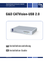
Guntermann & Drunck GmbH www.gdsys.de G&D CATVision-USB 2.0 DE Installationsanleitung EN Installation Guide A9100144-1.00 Zu dieser Dokumentation Diese Dokumentation wurde mit größter Sorgfalt erstellt und nach dem Stand der Technik auf Korrektheit überprüft. Für die Qualität, Leistungsfähigkeit sowie Marktgängigkeit des G&D-Produkts zu einem bestimmten Zweck, der von dem durch die Produktbeschreibung abgedeckten Leistungsumfang abweicht, übernimmt G&D weder ausdrücklich noch stillschweigend die Gewähr oder Verantwortung. Für Schäden, die sich direkt oder indirekt aus dem Gebrauch der Dokumentation ergeben, sowie für beiläufige Schäden oder Folgeschäden ist G&D nur im Falle des Vorsatzes oder der groben Fahrlässigkeit verantwortlich. Gewährleistungsausschluss G&D übernimmt keine Gewährleistung für Geräte, die nicht bestimmungsgemäß eingesetzt wurden. nicht autorisiert repariert oder modifiziert wurden. schwere äußere Beschädigungen aufweisen, welche nicht bei Lieferungserhalt angezeigt wurden. durch Fremdzubehör beschädigt wurden. G&D haftet nicht für Folgeschäden jeglicher Art, die möglicherweise durch den Einsatz der Produkte entstehen können. Warenzeichennachweis Alle Produkt- und Markennamen, die in diesem Handbuch oder in den übrigen Dokumentationen zu Ihrem G&D-Produkt genannt werden, sind Warenzeichen oder eingetragene Warenzeichen der entsprechenden Rechtsinhaber. Impressum © Guntermann & Drunck GmbH 2009. Alle Rechte vorbehalten. Version 1.00 – 04.11.2009 Guntermann & Drunck GmbH Dortmunder Str. 4a 57234 Wilnsdorf Germany Telefon Telefax +49 (0) 2739 8901-100 +49 (0) 2739 8901-120 http://www.GDsys.de [email protected] i · G&D CATVision-USB 2.0 Inhaltsverzeichnis Inhaltsverzeichnis Sicherheitshinweise .......................................................................................... 1 Die CATVision-USB 2.0-Serie ......................................................................... 2 Zusätzliche Funktionen erweiterter Varianten ..................................................... 2 Verfügbare Erweiterungen ................................................................................. 2 Lieferumfang .................................................................................................... Standardlieferumfang der CATVision-USB 2.0-Serie .......................................... Zusätzlicher Lieferumfang der erweiterten Varianten .......................................... Variante mit RS232-Übertragung .................................................................. Variante mit Audio- und RS232-Übertragung ............................................... 3 3 3 3 3 Installation ....................................................................................................... Vorbereitung ..................................................................................................... Installation des Rechnermoduls .......................................................................... Anschluss des Rechners ................................................................................ Optional: Anschluss der Geräte des lokalen Arbeitsplatzes ............................ Zusätzliche Schnittstellen der erweiterten Varianten ...................................... Anschlüsse für Datenübertragung ................................................................. Anschlüsse für Stromversorgung ................................................................... Installation des Arbeitsplatzmoduls .................................................................... Anschluss des entfernten Arbeitsplatzes ........................................................ Anschlüsse für USB 2.0-Geräte ..................................................................... Zusätzliche Schnittstellen der erweiterten Varianten ...................................... Anschlüsse für Datenübertragung ................................................................. Anschlüsse für Stromversorgung ................................................................... 4 4 4 5 5 6 6 6 7 7 7 7 8 8 Inbetriebnahme ................................................................................................. 9 Meldungen während des Startvorganges ............................................................. 9 Statusanzeigen ................................................................................................ 10 Statusanzeigen am Rechnermodul (CATVision-CPU) ................................. 10 Statusanzeigen am Arbeitsplatzmodul (CATVision-CON) .......................... 11 Technische Daten ........................................................................................... Allgemeine Eigenschaften ................................................................................ Individuelle Eigenschaften der Module ............................................................. Strom- und Leistungsaufnahme ........................................................................ 12 12 13 14 Anhang ........................................................................................................... 15 Empfehlungen zum Twisted-Pair-Kabel ........................................................... 15 G&D CATVision-USB 2.0 · ii Sicherheitshinweise Sicherheitshinweise Bitte lesen Sie die folgenden Sicherheitshinweise aufmerksam durch, bevor Sie das G&D-Produkt in Betrieb nehmen. Die Hinweise helfen Schäden am Produkt zu vermeiden und möglichen Verletzungen vorzubeugen. Halten Sie diese Sicherheitshinweise für alle Personen griffbereit, die dieses Produkt benutzen werden. Befolgen Sie alle Warnungen oder Bedienungshinweise, die sich am Gerät oder in dieser Bedienungsanleitung befinden. , Vorsicht vor Stromschlägen Um das Risiko eines Stromschlags zu vermeiden, sollten Sie das Gerät nicht öffnen oder Abdeckungen entfernen. Im Servicefall wenden Sie sich bitte an unsere Techniker. , Ziehen Sie den Netzstecker des Geräts vor Installationsarbeiten Stellen Sie vor Installationsarbeiten sicher, dass das Gerät spannungsfrei ist. Ziehen Sie den Netzstecker oder die Spannungsversorgung am Gerät ab. ! Ständigen Zugang zu den Netzsteckern der Geräte sicherstellen Achten Sie bei der Installation der Geräte darauf, dass die Netzstecker der Geräte jederzeit zugänglich bleiben. ! Stolperfallen vermeiden Vermeiden Sie bei der Verlegung der Kabel Stolperfallen. , Geerdete Spannungsquelle verwenden Betreiben Sie dieses Gerät nur an einer geerdeten Spannungsquelle. , Verwenden Sie ausschließlich das G&D-Netzteil Betreiben Sie dieses Gerät nur mit dem mitgelieferten oder in der Bedienungsanleitung aufgeführten Netzteil. ! Betreiben Sie das Gerät ausschließlich im vorgesehenen Einsatzbereich Die Geräte sind für eine Verwendung im Innenbereich ausgelegt. Vermeiden Sie extreme Kälte, Hitze oder Feuchtigkeit. 1 · G&D CATVision-USB 2.0 Die CATVision-USB 2.0-Serie Die CATVision-USB 2.0-Serie Die KVM-Extender der CATVision-USB 2.0-Serie übertragen die Signale von Tastatur, Maus und USB-Geräten sowie das Videosignal zwischen einem entfernten Arbeitsplatz und dem Rechner. Ein CATVision-System besteht aus zwei wesentlichen Komponenten: Rechnermodul: An das Rechnermodul (CATVision-CPU) wird der zu bedienende Rechner angeschlossen. Zusätzlich zum entfernten Arbeitsplatz kann am Rechnermodul ein (optionaler) lokaler Arbeitsplatz eingerichtet werden. Arbeitsplatzmodul: An das Arbeitsplatzmodul (CATVision-CON) werden die Geräte des entfernten Arbeitsplatzes (Monitor, Tastatur, Maus sowie USB-Geräte) angeschlossen. Über eine Twisted-Pair-Verkabelung der Kategorie 5 (oder höher) wird das Rechnermodul mit dem Arbeitsplatzmodul verbunden. Die zu überbrückende Distanz hängt von der Qualität des Twisted-Pair-Kabels (siehe Empfehlungen zum Twisted-Pair-Kabel auf Seite 15) und den zu übertragenden Signalen ab: Signaltyp bis 100 Meter bis 200 Meter bis 300 Meter Video USB 2.0 max. 57.600 bit/s max. 38.400 bit/s RS232 (Option) Tabelle 1: Übersicht der maximalen Übertragungslängen verschiedener Signaltypen Zusätzliche Funktionen erweiterter Varianten Audio: Die Audio-Übertragung (nur in Kombination mit der RS232-Option erhältlich) ermöglicht die bidirektionale Übertragung von Audiosignalen zwischen dem entfernten Arbeitsplatz und dem Rechner. Delay: Die Delay-Funktion gleicht Laufzeitunterschiede der verschiedenen Farbkanäle des RGB-Videosignals – die aus unterschiedlichen Längen der Adern der Twisted-Pair-Verkabelung resultieren – aus und sorgt für die bestmögliche Bildwiedergabe. RS232: Die RS232-Übertragung ermöglicht den Anschluss externer serieller Geräte an das Arbeitsplatzmodul. Die Signale des externen Gerätes werden transparent über das Arbeits- sowie das Rechnermodul zwischen dem Gerät und dem Rechner übertragen. Verfügbare Erweiterungen CV-Power: Die Erweiterung CV-Power ermöglicht die Bedienung der Taster ATX-Power und Reset des Rechners am entfernten Arbeitsplatz. G&D CATVision-USB 2.0 · 2 Lieferumfang Lieferumfang Standardlieferumfang der CATVision-USB 2.0-Serie 1 × Rechnermodul (CATVision-CPU) 1 × Arbeitsplatzmodul (CATVision-CON) 2 × Stromversorgungskabel (PowerCable-2 Standard) 1 × Geräteanschlusskabel (CPU-2) 2 × USB-Kabel (USB-AM/BM-2) 1 × Installationsanleitung 1 × Bedienungsanleitung Zusätzlicher Lieferumfang der erweiterten Varianten Im Lieferumfang einer erweiterten Variante der CATVision-Serie befinden sich zusätzlich die unten aufgeführten Kabel im Lieferumfang. Variante mit RS232-Übertragung 1 × serielles Anschlusskabel (RS232-M/F-2) Variante mit Audio- und RS232-Übertragung 2 × Audio-Kabel (Audio-M/M-2) 1 × serielles Anschlusskabel (RS232-M/F-2) HINWEIS: Die Geräte sind wahlweise als Desktop- oder Rackmount-Variante verfügbar. Die Rackmount-Varianten sind immer mit der Frontseite nach vorn im Rack zu platzieren. 3 · G&D CATVision-USB 2.0 Installation Installation Vorbereitung 1. Stellen Sie sicher, dass die zulässige Umgebungstemperatur (siehe Technische Daten auf Seite 12) in der unmittelbaren Nähe des Gerätes eingehalten und nicht durch andere Geräte beeinflusst wird. 2. Schalten Sie den am KVM-Extender anzuschließenden Rechner ggf. aus und ziehen Sie die Kabel von Monitor, Tastatur und Maus aus den Schnittstellen. 3. Platzieren Sie das Rechnermodul (CATVision-CPU) in Reichweite des Rechneranschlusskabels. Das Kabel ist in drei Varianten mit unterschiedlichen Kabellängen (2, 4 und 6 Meter) erhältlich. 4. Platzieren Sie das Arbeitsplatzmodul (CATVision-CON) in der Nähe des entfernten Arbeitsplatzes. 5. Entnehmen Sie die mitgelieferten Kabel der Verpackung des KVM-Extenders und legen Sie diese für die Installation der Geräte bereit. Installation des Rechnermoduls An das Rechnermodul CATVision-CPU wird der Rechner angeschlossen, dessen Signale an den entfernten Arbeitsplatz übertragen werden. Zusätzlich besteht die Möglichkeit, einen lokalen Arbeitsplatz an das Rechnermodul anzuschließen. TIPP: Beim Anschluss der Kabel ist vorzugsweise blockweise und von unten nach oben vorzugehen. So vermeiden Sie, dass bereits gesteckte Kabel die Sicht auf die Bezeichnung der Schnittstellen versperren. G&D CATVision-USB 2.0 · 4 Installation Anschluss des Rechners HINWEIS: Die Maus- und Tastatursignale beider Arbeitsplätze können wahlweise an die PS/2-Schnittstellen oder eine USB-Schnittstelle des Rechners gesendet werden. Verbinden Sie wahlweise die PS/2-Stecker des Rechneranschlusskabels oder die Schnittstelle USB K/M CPU – wie unten beschrieben – mit dem Rechner. Mouse Line In Line Out USB K/M CPU USB 2.0 Trans. Power RS 232 Keyb. Red. Power Transmission Monitor VGA Keyb. Mouse CPU USB 2.0 CPU VGA Keyb. Mouse CPU: Schließen Sie hier das Rechneranschlusskabel CPU-2 an. Verbinden Sie die nachfolgend genannten Stecker des Rechneranschlusskabels mit den entsprechenden Schnittstellen des Rechners: VGA: Stecken Sie diesen Stecker in den Videoausgang des Rechners. PS/2 violett: Stecken Sie diesen Stecker in die PS/2-Tastatur-Schnittstelle des Rechners. PS/2 grün: Stecken Sie diesen Stecker in die PS/2-Maus-Schnittstelle des Rechners. USB K/M CPU: Verbinden Sie eine USB-Schnittstelle des Rechners mit dieser Schnitt- stelle. Verwenden Sie hierzu das Kabel USB-AM/BM-2. USB 2.0 CPU: Verbinden Sie eine »High-Power« USB-Schnittstelle des Rechners mit dieser Schnittstelle. Verwenden Sie hierzu das Kabel USB-AM/BM-2. Optional: Anschluss der Geräte des lokalen Arbeitsplatzes Am Standort des Rechnermoduls können Sie optional eine weitere Zugriffsmöglichkeit auf den Rechner einrichten. Schließen die Tastatur und die Maus sowie den Monitor des lokalen Arbeitsplatzes an die nachfolgend aufgeführten Schnittstellen an. Mouse Line In Line Out USB K/M CPU USB 2.0 Trans. Power RS 232 Keyb. Red. Power Transmission Monitor VGA Keyb. Mouse CPU USB 2.0 CPU Keyb.: Schließen Sie die PS/2-Tastatur des lokalen Arbeitsplatzes an. Mouse: Schließen Sie die PS/2-Maus des lokalen Arbeitsplatzes an. Monitor: Schließen Sie den Monitor des lokalen Arbeitsplatzes an. 5 · G&D CATVision-USB 2.0 Installation Zusätzliche Schnittstellen der erweiterten Varianten Mouse Line In Line Out USB K/M CPU USB 2.0 Trans. Power RS 232 Keyb. Red. Power Transmission Monitor VGA Keyb. Mouse CPU USB 2.0 CPU RS232: Verbinden Sie eine 9-polige serielle Schnittstelle des Rechners mit dieser Schnittstelle. Verwenden Sie hierzu das Kabel RS232-M/F-2. Line In: Verbinden Sie die Line-Out-Schnittstelle des Rechners mit dieser Schnittstelle. Verwenden Sie hierzu das Kabel Audio-M/M-2. Line Out: Verbinden Sie die Line-In-Schnittstelle des Rechners mit dieser Schnittstelle. Verwenden Sie hierzu das Kabel Audio-M/M-2. Anschlüsse für Datenübertragung Mouse Line In Line Out USB K/M CPU USB 2.0 Trans. Power RS 232 Keyb. Red. Power Transmission Monitor VGA Keyb. Mouse CPU USB 2.0 CPU Transmission: Stecken Sie hier das als Zubehör erhältliche Twisted-Pair-Kabel der Kategorie 5 (oder höher) ein. Das andere Ende des Kabels ist mit der TransmissionSchnittstelle des Arbeitsplatzmoduls CATVision-CON zu verbinden. USB 2.0 Trans.: Stecken Sie hier das als Zubehör erhältliche Twisted-Pair-Kabel der Kategorie 5 (oder höher) ein. Das andere Ende des Kabels ist mit der USB 2.0 Trans.Schnittstelle des Arbeitsplatzmoduls CATVision-CON zu verbinden. Anschlüsse für Stromversorgung Mouse Line In Line Out USB K/M CPU USB 2.0 Trans. Power RS 232 Keyb. Red. Power Transmission Monitor VGA Keyb. Mouse CPU USB 2.0 CPU Power: Stecken Sie hier das mitgelieferte Kaltgerätekabel PowerCable-2 Standard ein. Red. Power: Optional kann über diese Buchse das Netzteil Power-Set 12-Typ 1 angeschlossen werden. Hierdurch wird eine zweite, redundante Stromversorgung des Rechnermoduls erreicht. G&D CATVision-USB 2.0 · 6 Installation Installation des Arbeitsplatzmoduls Anschluss des entfernten Arbeitsplatzes Line In Keyb. USB Mouse Micro In Speaker USB 2.0 Trans. Power RS 232 Keyb. PS/2 Mouse Service Monitor Transmission Red. Power HINWEIS: Die Maus sowie die Tastatur des entfernten Arbeitsplatzes können wahlweise als PS/2- oder USB-Gerät angeschlossen werden. PS/2 Keyb.: Schließen Sie hier die PS/2-Tastatur des Arbeitsplatzes an. PS/2 Mouse: Schließen Sie hier die PS/2-Maus des Arbeitsplatzes an. USB Keyb.: Schließen Sie hier die USB-Tastatur des Arbeitsplatzes an. USB Mouse: Schließen Sie hier die USB-Maus des Arbeitsplatzes an. Monitor: Schließen Sie hier den Monitor des Arbeitsplatzes an. Anschlüsse für USB 2.0-Geräte Device USB 2.0 Devices Status Power Power Red. Main Remote Active Status USB 2.0 Devices: Stecken Sie an diese Schnittstellen bis zu vier USB-Geräte an. Der am Rechnermodul CATVision-CPU angeschlossene Recher kann diese USBGeräte – zusätzlich zu den direkt am Rechner angeschlossenen USB-Geräten – nutzen. Zusätzliche Schnittstellen der erweiterten Varianten Line In Keyb. USB Mouse Micro In Speaker USB 2.0 Trans. Power RS 232 Keyb. PS/2 Mouse Service Monitor Transmission Red. Power RS232: Verbinden Sie das serielle Endgerät mit dieser Schnittstelle. Line In: Schließen Sie hier eine beliebige Audioquelle (z. B. einen MP3-Player) an. Micro In: Schließen Sie hier ein Mikrofon an. Speaker: Schließen Sie hier die Lautsprecher des Arbeitsplatzes an. 7 · G&D CATVision-USB 2.0 Installation Anschlüsse für Datenübertragung Line In Keyb. USB Mouse Micro In Speaker USB 2.0 Trans. Power RS 232 Keyb. PS/2 Mouse Service Monitor Transmission Red. Power Transmission: Stecken Sie hier das mit der Transmission-Schnittstelle des Rechnermoduls verbundene Twisted-Pair-Kabel ein. USB 2.0 Trans.: Stecken Sie hier das mit der USB 2.0 Trans.-Schnittstelle des Rechner- moduls verbundene Twisted-Pair-Kabel ein. Anschlüsse für Stromversorgung Line In Keyb. USB Mouse Micro In Speaker USB 2.0 Trans. Power RS 232 Keyb. PS/2 Mouse Service Monitor Transmission Red. Power Power: Stecken Sie hier das mitgelieferte Kaltgerätekabel PowerCable-2 Standard ein. Red. Power: Optional kann über diese Buchse das Netzteil Power-Set 12-Typ 1 angeschlossen werden. Hierdurch wird eine zweite, redundante Stromversorgung desRechnermoduls erreicht. G&D CATVision-USB 2.0 · 8 Inbetriebnahme Inbetriebnahme Schalten Sie die Schalter der Netzteile des Rechner- und des Arbeitsplatzmodules ein. Meldungen während des Startvorganges Während des Startvorganges (System Startup) werden auf dem Bildschirm des lokalen Arbeitsplatzes verschiedene Informationen angezeigt. Besteht eine funktionierende Datenverbindung zwischen dem Rechner- und dem Arbeitsplatzmodul, werden diese Meldungen auch auf dem Bildschirm des entfernten Arbeitsplatzes angezeigt. Neben der Anzeige der Tastenkombination zum Aufruf des On-Screen-Displays »AdonIS« werden Ihnen folgende Informationen angezeigt: Eigenschaft Status Bedeutung pc unit found Rechner ist eingeschaltet und auf der PS/2-Schnittstelle und/oder dem USB-Bus ist Spannung vorhanden not found keine Spannung auf PS/2- und USB-Bus vorhanden Schalten Sie ggf. den Rechner ein und stellen Sie sicher, dass entweder die PS/2-Stecker des Rechneranschlusskabels oder die Schnittstelle »USB K/M CPU« des Rechnermoduls mit dem Rechner verbunden wurde(n). searching Anschluss des Rechners am Rechnermodul wird geprüft found Twisted-Pair-Verkabelung zwischen Rechner- und Arbeitsplatzmodul in Ordnung not found fehlende oder fehlerhafte Twisted-Pair-Verkabelung zwischen Rechner- und Arbeitsplatzmodul searching Verbindung zwischen Rechner- und Arbeitsplatzmodul wird geprüft found Maus des lokalen Arbeitsplatzes korrekt am Rechnermodul angeschlossen not found keine Maus des lokalen Arbeitsplatzes am Rechnermodul angeschlossen searching Anschluss der Maus des lokalen Arbeitsplatzes am Rechnermodul wird geprüft found Tastatur des lokalen Arbeitsplatzes korrekt am Rechnermodul angeschlossen not found keine Tastatur des lokalen Arbeitsplatzes am Rechnermodul angeschlossen searching Anschluss der Tastatur des lokalen Arbeitsplatzes am Rechnermodul wird geprüft remote unit local mouse local keyboard 9 · G&D CATVision-USB 2.0 Statusanzeigen Statusanzeigen Die LEDs an den Frontseiten des Rechner- sowie des Arbeitsplatzmoduls geben Ihnen die Möglichkeit, den Betriebsstatus jederzeit zu kontrollieren. Statusanzeigen am Rechnermodul (CATVision-CPU) Power Red. Main Local Active Status CPU Service Active Status Bereich LED Status Bedeutung Power Red. an Netzteil angeschlossen, erforderliche Spannung vorhanden aus kein Netzteil angeschlossen oder keine Verbindung zum Stromnetz Main an Netzteil eingeschaltet, erforderliche Spannung vorhanden aus Netzteil ausgeschaltet oder keine Verbindung zum Stromnetz Active an lokaler Arbeitsplatz aktiv aus entfernter Arbeitsplatz aktiv blinkt Tastatur des lokalen Arbeitsplatzes nicht gefunden an Gerät betriebsbereit aus keine Spannung auf PS/2-Schnittstelle und USB-Bus vorhanden blinkt interne Kommunikation fehlerhaft an der lokale oder entfernte Arbeitsplatz bedienen den Rechner aus zurzeit kein Zugriff eines Arbeitsplatzes auf den Rechner an Tastatur- und Mausemulation in Ordnung aus Tastatur- und Mausemulation fehlerhaft Local Status CPU Active Status G&D CATVision-USB 2.0 · 10 Statusanzeigen Statusanzeigen am Arbeitsplatzmodul (CATVision-CON) Device USB 2.0 Devices Status Power Power Red. Main Remote Active Status Bereich LED Status Bedeutung Device Status an Verbindung zum Rechnermodul über Twisted-Pair- Verkabelung in Ordnung und USB-Komponente betriebsbereit aus zurzeit keine Verbindung zum Rechnermodul möglich oder USB-Komponente nicht betriebsbereit an Spannung des USB-Übertragungsmoduls in Ordnung aus keine Spannung am USB-Übertragungsmoduls vorhanden an Netzteil angeschlossen, erforderliche Spannung vorhanden aus kein Netzteil angeschlossen oder keine Verbindung zum Stromnetz an Netzteil eingeschaltet, erforderliche Spannung vorhanden aus Netzteil ausgeschaltet oder keine Verbindung zum Stromnetz an entfernter Arbeitsplatz aktiv aus lokaler Arbeitsplatz aktiv blinkt Tastatur des entfernten Arbeitsplatzes nicht gefunden an Gerät betriebsbereit aus keine Spannung auf PS/2-Schnittstelle und USB-Bus vorhanden blinkt interne Kommunikation fehlerhaft Power Power Red. Main Remote Active Status 11 · G&D CATVision-USB 2.0 Technische Daten Technische Daten Allgemeine Eigenschaften CATVISION-USB 2.0-SERIE Video USB 2.0 Audio kostenpflichtige Option RS232 kostenpflichtige Option Signaltyp: VGA (RGBHV, RGsB, RBGc) Videoauflösung: max. 1920 x 1440 @ 75 Hz Videobandbreite: 250 MHz Vertikalfrequenz: 50 Hz bis 150 Hz Horizontalfrequenz: 30 kHz bis 135 kHz Reichweite: max. 300 Meter Übertragungsart: transparent Übertragungsrate: bis 480 Mbit/s Unterstützte Geräte: High-Power-Devices (bis 500 mA) Reichweite: max. 100 Meter Übertragungsart: transparent, bidirektional Auflösung: 18 bit, digital Mikrofon-Vorverstärkung: 20 db Abtastrate: 48 kHz Bandbreite: 22 kHz Übertragungsart: transparent Übertragene Signale: RxD, TxD, RTS, CTS, DTR, DSR Übertragungsrate: max. 57.600 bit/s (bis 100 Meter); max. 38.400 bit/s (bis 200 Meter) Hauptstromversorgung Typ: Internes Netzteil Anschluss: Kaltgerätestecker (IEC-320 C14) Spannung: AC 100-240 V/60-50 Hz Redundante Stromversorgung Typ: Externes Netzteil Anschluss: miniDIN-4 Power-Buchse Spannung: +12 VDC Einsatzumgebung Temperatur: +5 bis +40 °C Luftfeuchte: < 80%, nicht kondensierend Konformität CE, RoHs G&D CATVision-USB 2.0 · 12 Technische Daten Individuelle Eigenschaften der Module CATVISION-ARU2-CPU | RECHNERMODUL Schnittstellen für Rechner Video: 1 × D-Sub HD 15-Buchse via Rechneranschlusskabel PS/2-Tastatur und Maus: 2 × PS/2-Buchse via Rechneranschlusskabel USB: 1 × USB-B-Buchse (Tastatur-/Mausdaten) 1 × USB-B-Buchse (transparent) Audio: kostenpflichtige Option 1 × 3,5-mm-Klinkenbuchse (Line In) 1 × 3,5-mm-Klinkenbuchse (Line Out) RS232: kostenpflichtige Option 1 × D-Sub 9-Buchse Schnittstellen für lokalen Arbeitsplatz Video: 1 × D-Sub HD 15-Buchse PS/2-Tastatur und -Maus: 2 × PS/2-Buchse Schnittstellen zum Arbeitsplatzmodul Maus-/Tastaturdaten: 1 × RJ45-Buchse USB 2.0-Geräte: 1 × RJ45-Buchse Gehäuse Material: Aluminium eloxiert Maße (B x H x T): 270 × 44 × 210 mm CATVISION-ARU2-CON | ARBEITSPLATZMODUL Schnittstellen für Arbeitsplatz Monitor: 1 × D-Sub HD 15-Buchse Tastatur: 1 × PS/2-Buchse 1 × USB-A-Buchse Maus: 1 × PS/2-Buchse 1 × USB-A-Buchse USB 2.0-Geräte: 4 × USB-A-Buchse (Frontseite) Audio: kostenpflichtige Option 1 × 3,5-mm-Klinkenbuchse (Line In) 1 × 3,5-mm-Klinkenbuchse (Micro In) 1 × 3,5-mm-Klinkenbuchse (Speaker) RS232: kostenpflichtige Option 1 × D-Sub 9-Stecker Schnittstellen zum Rechnermodul Maus-/Tastaturdaten: 1 × RJ45-Buchse USB 2.0-Geräte: 1 × RJ45-Buchse Gehäuse Material: Aluminium eloxiert Maße (B x H x T): 270 × 44 × 210 mm 13 · G&D CATVision-USB 2.0 Technische Daten Strom- und Leistungsaufnahme STROMAUFNAHME CATVision-ARU2 100 VAC, 60 Hz: 0,2 A (CPU); 0,5 A (CON) 240 VAC, 50 Hz: 0,1 A (CPU); 0,2 A (CON) 12 VDC: 0,7 A (CPU); 1,8 A (CON) LEISTUNGSAUFNAME (MAX.) CATVision-ARU2 100 VAC, 60 Hz: 10,2 W (CPU); 24,6 W (CON) 240 VAC, 50 Hz: 10,8 W (CPU); 24,4 W (CON) 12 VDC: 07,3 W (CPU); 19,9 W (CON) G&D CATVision-USB 2.0 · 14 Anhang Anhang Empfehlungen zum Twisted-Pair-Kabel Die Übertragung der Signale des CATVision-Systems erfolgt über Twisted-Pair-Kabel der Kategorie 5e (oder höher). HINWEIS: Das Verbinden mehrerer Teilstrecken einer Kabelverbindung über Patchfelder und Anschlussdosen ist möglich. Die Einbindung aktiver Komponenten wie Netzwerk-Switches, Hubs oder Repeater, ist nicht zulässig. Die Datenübertragung ist mit handelsüblichen, standardkonformen Twisted-PairKabeln der Kategorie 5e (oder höher) bis mindestens 70 Meter zuverlässig möglich. Die tatsächlich erreichbare Entfernung hängt von den Eigenschaften und der Qualität des verwendeten Kabels ab. Hochqualitative S-STP-Leitungen mit einem Drahtdurchmesser der Codierung AWG 24 können bis zu 100 Meter überbrücken. Patchleitungen mit einem Drahtdurchmesser der Codierung AWG 26 überbrücken maximal 70 Meter Entfernung. Um auch in schwierigen Umgebungen einen zuverlässigen Betrieb zu gewährleisten, sind für Längen über 70 Metern Kabel der Codierung AWG 24 oder besser zu verwenden: Drahtstärke Kabeltyp Kategorie Empfehlung AWG 24 Installationskabel 5e, 6 oder 7 bis 100 Meter AWG 26/27 Patchkabel 5e, 6 oder 7 bis 70 Meter WICHTIG: Bei Geräten der CATVision-USB 2.0-Serie ohne Delay-Funktion ist eine maximale Laufzeitdifferenz (Skew) von 3 ns auf der Übertragungsstrecke zulässig. Geräte mit Delay-Funktion erlauben den Einsatz von Twisted-Pair-Verkabelungen mit einer Laufzeitdifferenz von bis zu 46 ns. Während des Testbetriebs unter Laborbedingungen haben die folgenden Kabel die besten Ergebnisse erzielt: bis 70 Meter: Dätwyler uninet® 7702 flex 4P (AWG 26) bis 100 Meter: Dätwyler uninet® 5502 4P / 2x4P BD (AWG 24) 15 · G&D CATVision-USB 2.0 NOTIZEN NOTIZEN NOTIZEN About this guide This guide is authored with special diligence and verified by the state of the art for correctness. G&D neither explicitly nor implicitly takes guarantee or responsibility for the quality, efficiency and marketability of the product when used for a certain purpose that differs from the scope of service covered by this guide. For losses, which directly or indirectly result from the use of the documentation as well as for incidental damages or subsequent damages, G&D is liable only in the cases of intent or gross negligence. Warranty exclusion In the following cases, G&D will not accept warranty claims: The devices were not used as intended. The devices were repaired or modified by unauthorized personnel. The devices offer extensive external damage that was not reported at time of delivery. The devices were damaged by third-party accessories. G&D will assume no liability for any consequential damages that may arise from the use of the products. Trademark credits All product and company names mentioned in this guide and other documents you have received with your G&D product may be trademarks or trade names of their respective owners. Impressum © Guntermann & Drunck GmbH 2009. All rights reserved. Version 1.00 – 04/11/2009 Guntermann & Drunck GmbH Dortmunder Str. 4a 57234 Wilnsdorf Germany Phone +49 2739 8901-100 Fax +49 2739 8901-120 http://www.GDsys.de [email protected] i · G&D CATVision-USB 2.0 Contents Contents Safety guidelines ............................................................................................... 1 CATVision-USB 2.0 series ............................................................................... 2 Additional functions of expanded variants .......................................................... 2 Available expansions ......................................................................................... 2 Scope of delivery ............................................................................................... Standard scope of delivery of the CATVision-USB 2.0 series ............................... Additional scope of delivery of the expanded variants ......................................... Variant with RS232 transmission .................................................................. Variant with audio and RS232 transmission .................................................. 3 3 3 3 3 Installation ....................................................................................................... Preparation ....................................................................................................... Installing the computer module .......................................................................... Connecting the computer ............................................................................. Optional: Connecting the local console devices ............................................. Additional interfaces of the expanded variants .............................................. Connections for data transmission ................................................................ Connections for power supply ...................................................................... Installing the user module .................................................................................. Connecting the remote console ..................................................................... Connections for USB 2.0 devices .................................................................. Additional interfaces of the expanded variants .............................................. Connections for data transmission ................................................................ Connections for power supply ...................................................................... 4 4 4 5 5 6 6 6 7 7 7 7 8 8 Initiation .......................................................................................................... 9 Messages during booting .................................................................................... 9 Status displays ................................................................................................ 10 Status displays at the computer module (CATVision-CPU) ......................... 10 Status displays at the user module (CATVision-CON) ................................. 11 Technical Data ............................................................................................... General features .............................................................................................. Individual features of the modules .................................................................... Current and power consumption ...................................................................... 12 12 13 14 Appendix ........................................................................................................ 15 Recommendations for twisted pair cables ......................................................... 15 G&D CATVision-USB 2.0 · ii Safety guidelines Safety guidelines Please read the following safety guidelines attentively before you start running the G&D product. The guidelines help to avoid damage to the product and prevent possible injuries. Inform all persons that use this equipment in detail about these safety guidelines. Observe all warnings or operating instructions put on the device or stated in this operating guide. , Avoid the risk of electric shock To avoid the risk of electric shock, do not open the device or remove the covers. If service is required, please contact our technicians. , Disconnect the main power plug or the power supply before installation Before installation, ensure that the device has been disconnected from the power source. Disconnect the main power plug or the power supply of the device. , Ensure constant access to the power plugs Ensure during the installation of the devices that the power plugs remain accessible. ! Ensure proper installation position For reasons of electric safety, the device must be installed in an upright, horizontal position. ! Ensure proper installation position For reasons of electric safety, devices with ventilation openings must be installed in an upright, horizontal position. ! Avoid the risk of tripping over cables Ensure that there is no risk of tripping over cables. ! Only use a grounded electrical outlet Operate this device by using a grounded electrical outlet. ! Use only the provided G&D power pack Operate this device with the provided G&D power pack or with the power packs listed in the operating manual. ! Operate the device only in the intended area of application This device has been designed for indoor use. Do not expose it to extreme cold, heat or humidity. 1 · G&D CATVision-USB 2.0 CATVision-USB 2.0 series CATVision-USB 2.0 series The KVM extenders of the CATVision-USB 2.0 series transmit the signals of keyboard, mouse and USB devices as well as the video signal between a remote console and the computer. A CATVision system consists of two main components: Computer module: The computer to be operated is connected to the computer mod- ule (CATVision-CPU). Additionally to the remote console, an (optional) local console can be installed at the computer module. User module: The devices of the remote console (monitor, keyboard, mouse as well as USB devices) are connected to the user module (CATVision-CON). A twisted pair cable (category 5 or better) connects the computer module to the user module. The distance to be bridged depends on the quality of the twisted pair cable (see Recommendations for twisted pair cables on page 15) and the signals to be transmitted: up to 100 meters up to 200 meters up to300 meters Video USB 2.0 max. 57.600 bit/s max. 38.400 bit/s Signal type RS232 (option) Table 1: Overview of the maximum transmission lengths of different signal types Additional functions of expanded variants Audio: The Audio transmission (only available in combination with the RS232 option) enables the bidirectional transmission of audio signals between the remote console and the computer. Delay: The Delay function compensates the runtime delays of the different colour channels of the RGB video signal. Those runtime delays result from the different wire lengths of the twisted pair cabling. Through this compensation, the image can be displayed in the best possible way. RS232: The RS232 transmission enables the connection of external serial devices at the user module. The user module and the computer module are used to transmit the signals of the external device transparently between the device and the computer. Available expansions CV-Power: The CV-Power expansion enables the user to operate the ATX-Power and Reset button of the computer at the remote console. G&D CATVision-USB 2.0 · 2 Scope of delivery Scope of delivery Standard scope of delivery of the CATVision-USB 2.0 series 1 × computer module (CATVision-CPU) 1 × user module (CATVision-CON) 2 × power cable (PowerCable-2 Standard) 1 × device connection cable (CPU-2) 2 × USB cable (USB-AM/BM-2) 1 × installation guide 1 × operation guide Additional scope of delivery of the expanded variants The scope of delivery of an expanded variant of the CATVision series additionally includes the cables listed below. Variant with RS232 transmission 1 × serial connection cable (RS232-M/F-2) Variant with audio and RS232 transmission 2 × audio cable (Audio-M/M-2) 1 × serial connection cable (RS232-M/F-2) NOTE: The devices are available as desktop or as rackmount variant. The rackmount variants must be placed into the rack with the front panel facing forwards. 3 · G&D CATVision-USB 2.0 Installation Installation Preparation 1. Please ensure to comply with the ambient temperature limit (see Technical Data on page 12) in the surrounding of the device. The ambient temperature limit must not be influenced by other devices. 2. Switch off the computer to be connected to the KVM extender and unplug the monitor, keyboard and mouse cables from the interfaces. 3. Place the computer module (CATVision-CPU) in reach of the computer connection cable. The cable is available in three different lengths (2, 4 and 6 meters). 4. Place the user module (CATVision-CON) close to the remote console. 5. Take the supplied cables from the packing of the KVM extender and have them available for installation. Installing the computer module The computer whose signals are transmitted to the remote console is connected to the CATVision-CPU computer module. It is also possible to connect a local console to the computer module. ADVICE: Preferably connect the cables block by block and from bottom to top. This way, already connected cables do not block the view at the interface descriptions. G&D CATVision-USB 2.0 · 4 Installation Connecting the computer NOTE: The mouse and keyboard signals of both consoles can either be sent to the PS/2 interfaces or a USB interface of the computer. Connect either the PS/2 plugs of the computer connection cable or the USB K/M CPU interface to the computer. Mouse Line In Line Out USB K/M CPU USB 2.0 Trans. Power RS 232 Keyb. Red. Power Transmission Monitor VGA Keyb. Mouse CPU USB 2.0 CPU VGA Keyb. Mouse CPU: Connect the CPU-2 computer connection cable to this interface. Connect the plugs of the computer connection cable that are mentioned in the following to the respective interfaces of the computer: VGA: Insert this plug into the video output of the computer. PS/2 purple: Insert this plug into the PS/2 keyboard interface of the computer. PS/2 green: Insert this plug into the PS/2 mouse interface of the computer. USB K/M CPU: Use the USB-AM/BM-2 cable to connect a USB interface of the compu- ter to this interface. USB 2.0 CPU: Use the USB-AM/BM-2 cable to connect a »high power« USB interface of the computer to this interface. Optional: Connecting the local console devices Additionally to the remote console, an (optional) local console can be installed at the computer module. Connect keyboard and mouse as well as the monitor of the local console to the interfaces listed in the following. Mouse Line In Line Out USB K/M CPU USB 2.0 Trans. Power RS 232 Keyb. Red. Power Transmission Monitor VGA Keyb. Mouse CPU USB 2.0 CPU Keyb.: Connect the PS/2 keyboard of the local console. Mouse: Connect the PS/2 mouse of the local console. Monitor: Connect the monitor of the local console. 5 · G&D CATVision-USB 2.0 Installation Additional interfaces of the expanded variants Mouse Line In Line Out USB K/M CPU USB 2.0 Trans. Power RS 232 Keyb. Red. Power Transmission Monitor VGA Keyb. Mouse CPU USB 2.0 CPU RS232: Use the RS232-M/F-2 cable to connect a 9-pin serial interface of the computer to this interface. Line In: Use the Audio-M/M-2 cable to connect the Line Out interface of the computer to this interface. Line Out: Use the Audio-M/M-2 cable to connect the Line In interface of the computer to this interface. Connections for data transmission Mouse Line In Line Out USB K/M CPU USB 2.0 Trans. Power RS 232 Keyb. Red. Power Transmission Monitor VGA Keyb. Mouse CPU USB 2.0 CPU Transmission: Insert a twisted pair cable (category 5 or better), which is available as accessory into this interface. Connect the other end of the cable to the Transmission interface of the CATVision-CON user module. USB 2.0 Trans.: Insert a twisted pair cable (category 5 or better), which is available as accessory into this interface. Connect the other end of the cable to the USB 2.0 Trans. interface of the CATVision-CON user module. Connections for power supply Mouse Line In Line Out USB K/M CPU USB 2.0 Trans. Power RS 232 Keyb. Red. Power Transmission Monitor VGA Keyb. Mouse CPU USB 2.0 CPU Power: Insert the supplied PowerCable-2 Standard IEC cable into this interface. Red. Power: The Power-Set 12-Typ 1 can be optionally connected to this socket, which provides a second, redundant power supply of the computer module. G&D CATVision-USB 2.0 · 6 Installation Installing the user module Connecting the remote console Line In Keyb. USB Mouse Micro In Speaker USB 2.0 Trans. Power RS 232 Keyb. PS/2 Mouse Service Monitor Transmission Red. Power NOTE: Mouse and keyboard of the remote console can either be PS/2 or USB devices. PS/2 Keyb.: Connect the PS/2 keyboard of the console to this interface. PS/2 Mouse: Connect the PS/2 mouse of the console to this interface. USB Keyb.: Connect the USB keyboard of the console to this interface. USB Mouse: Connect the USB mouse of the console to this interface. Monitor: Connect the console monitor to this interface. Connections for USB 2.0 devices Device USB 2.0 Devices Status Power Power Red. Main Remote Active Status USB 2.0 Devices: Connect up to four USB devices to those interfaces. The computer, which is connected to the CATVision-CPU computer module is able to use those USB devices additionally to the USB devices that are directly connected to the computer. Additional interfaces of the expanded variants Line In Keyb. USB Mouse Micro In Speaker USB 2.0 Trans. Power RS 232 Keyb. PS/2 Mouse Service Monitor Transmission Red. Power RS232: Connect the serial end device to this interface. Line In: Connect any audio source (e. g. an mp3 player) to this interface. Micro In: Connect a microphone to this interface. Speaker: Connect the console speakers to this interface. 7 · G&D CATVision-USB 2.0 Installation Connections for data transmission Line In Keyb. USB Mouse Micro In Speaker USB 2.0 Trans. Power RS 232 Keyb. PS/2 Mouse Service Monitor Transmission Red. Power Transmission: Insert the twisted pair cable, which is connected to the Transmission interface of the computer module into this interface. USB 2.0 Trans.: Insert the twisted pair cable, which is connected to the USB 2.0 Trans. interface of the computer module into this interface. Connections for power supply Line In Keyb. USB Mouse Micro In Speaker USB 2.0 Trans. Power RS 232 Keyb. PS/2 Mouse Service Monitor Transmission Red. Power Power: Insert the supplied PowerCable-2 Standard IEC cable into this interface. Red. Power: The Power-Set 12-Typ 1 can be optionally connected to this socket, which provides a second, redundant power supply of the computer module. G&D CATVision-USB 2.0 · 8 Initiation Initiation Use the buttons on the power packs to switch on the computer module and the user module. Messages during booting During the System Startup, various information are displayed at the monitor of the local console. If a data connection between the computer module and the user module has been established, those messages are also displayed at the remote console monitor. Beside the key combination to call the »AdonIS« on-screen display, the following information are displayed: Feature Status Meaning pc unit found computer is switched on and the PS/2 interface and/or the USB bus provides voltage not found no voltage at PS/2 and USB bus If necessary, switch the computer on and ensure that either the PS/2 plugs of the computer connection cable or the »USB K/M CPU« interface of the computer module are connected to the computer. searching checking connection of computer at computer module found twisted pair cabling between computer module and user module ok not found non-existent or defective twisted pair cabling between computer module and user module searching checking connection between computer module and user module found local console mouse properly connected to the computer module not found no local mouse connected to the computer module searching checking connection of local console mouse at computer module found local console keyboard properly connected to the computer module not found no local keyboard connected to the computer module searching checking connection of local console keyboard at computer module remote unit local mouse local keyboard 9 · G&D CATVision-USB 2.0 Status displays Status displays The LEDs on the front panels of the computer module or the user module enable you to control the operating status at all times. Status displays at the computer module (CATVision-CPU) Power Red. Main CPU Local Active Status Service Active Status Range LED Status Meaning Power Red. on power pack connected, necessary voltage supplied off no power pack connected or no connection to mains Main on power pack switched on, necessary voltage supplied off power pack switched off or no connection to mains Active on local console active off remote console active blinking no local console keyboard found on device ready for operation off no voltage at PS/2 interface and USB bus blinking defective internal communication on computer is operated by local and remote console off computer is not accessed by a console on keyboard and mouse emulation ok off keyboard and mouse emulation defective Local Status CPU Active Status G&D CATVision-USB 2.0 · 10 Status displays Status displays at the user module (CATVision-CON) Device USB 2.0 Devices Status Power Power Remote Red. Main Active Status Range LED Status Meaning Device Status on connection to computer module via twisted pair cable ok and USB component ready for operation off no conenction to computer module possible or USB component not ready for operation on voltage of USB transmission module ok off no voltage at USB transmission module on power pack connected, necessary voltage supplied off no power pack connected or no connection to mains on power pack switched on, necessary voltage supplied off power pack switched off or no connection to mains on remote console active off local console active blinking no remote console keyboard found on device ready for operation off no voltage at PS/2 interface and USB bus blinking defective internal communication Power Power Red. Main Remote Active Status 11 · G&D CATVision-USB 2.0 Technical Data Technical Data General features CATVISION-USB 2.0 SERIES Video USB 2.0 Audio purchasable option Signal type: VGA (RGBHV, RGsB, RBGc) Video resolution: max. 1920 x 1440 @ 75 Hz Video bandwidth: 250 MHz Vertical frequency: 50 Hz to 150 Hz Horizontal frequency: 30 kHz to 135 kHz Range: max. 300 meters Transmission type: transparent Transmission rate: up to 480 Mbit/s Supported devices: High-Power-Devices (up to 500 mA) Range: max. 100 meters Transmission type: transparent, bidirectional Resolution: 18 bit, digital Microphone preamplification: 20 db RS232 purchasable option Main power supply Redundant power supply Sampling rate: 48 kHz Bandwidth: 22 kHz Transmission type: transparent Transmitted signals: RxD, TxD, RTS, CTS, DTR, DSR Transmission rate: max. 57.600 bit/s (up to 100 meters); max. 38.400 bit/s (up to 200 meters) Type: internal power pack Connection: IEC plug(IEC-320 C14) Voltage: AC 100-240 V/60-50 Hz Type: eExternal power pack Connection: miniDIN-4 Power socket Voltage: Operating environment Temperature: Air humidity: Conformity +12 VDC +5 to +40 °C < 80%, non-condensing CE, RoHs G&D CATVision-USB 2.0 · 12 Technical Data Individual features of the modules CATVISION-ARU2-CPU | COMPUTER MODULE Interfaces for computer Video: via connection cable 1 × D-Sub HD 15 socket PS/2 keyboard and mouse: via connection cable 2 × PS/2 socket USB: 1 × USB-B socket (keyboard/mouse data) 1 × USB-B socket (transparent) Audio: purchasable option 1 × 3,5-mm jack plug (Line In) 1 × 3,5-mm jack plug (Line Out) RS232: purchasable option 1 × D-Sub 9 socket Interfaces for local console Video: 1 × D-Sub HD 15 socket PS/2 keyboard and mouse: 2 × PS/2 socket Interfaces to user module Mouse/Keyboard data: 1 × RJ45 socket USB 2.0 devices: 1 × RJ45 socket Casing Material: anodised aluminium Dimensions (W x H x D): 270 × 44 × 210 mm CATVISION-ARU2-CON | USER MODULE Interfaces for console Monitor: 1 × D-Sub HD 15 socket Keyboard: 1 × PS/2 socket 1 × USB-A socket Mouse: 1 × PS/2 socket 1 × USB-A socket USB 2.0 devices: 4 × USB-A socket (front panel) Audio: purchasable option 1 × 3,5-mm jack plug (Line In) 1 × 3,5-mm jack plug (Micro In) 1 × 3,5-mm jack plug (Speaker) RS232: purchasable option 1 × D-Sub 9 plug Interfaces to computer module Mouse/Keyboard data: 1 × RJ45 socket USB 2.0 devices: 1 × RJ45 socket Casing Material: anodised aluminium Dimensions (W x H x D): 270 × 44 × 210 mm 13 · G&D CATVision-USB 2.0 Technical Data Current and power consumption CURRENT CONSUMPTION CATVision-ARU2 100 VAC, 60 Hz: 0,2 A (CPU); 0,5 A (CON) 240 VAC, 50 Hz: 0,1 A (CPU); 0,2 A (CON) 12 VDC: 0,7 A (CPU); 1,8 A (CON) POWER CONSUMPTION (MAX.) CATVision-ARU2 100 VAC, 60 Hz: 10,2 W (CPU); 24,6 W (CON) 240 VAC, 50 Hz: 10,8 W (CPU); 24,4 W (CON) 12 VDC: 07,3 W (CPU); 19,9 W (CON) G&D CATVision-USB 2.0 · 14 Appendix Appendix Recommendations for twisted pair cables All signals of the CATVision system are transmitted via twisted pair cables (category 5 or better). NOTE: It is permitted to connect several segments of a cable connection with patch panels and connection ports. It is, however, not permitted to connect active components such as network switches, hubs or repeaters are not permitted. The data transmission is reliable over a distance of at least 70 meters using a regular standard twisted pair cable (category 5e or better). The distance that can actually be bridged depends on the quality of the applied cable. High-quality S-STP cables with an AWG24 wire gauge coding can bridge a distance of up to 100 meters. Patch cables with an AWG26 wire gauge coding can only bridge a maximum of 70 meters. In order to ensure a reliable operation even in difficult environments, installation cables with at least AWG24 coding have to be used to bridge lengths over 70 meters: Wire gauge Cable type Category Recommendation AWG 24 Installation cable 5e, 6 or 7 up to 100 meters AWG 26/27 Patch cable 5e, 6 or 7 up to 70 meters IMPORTANT: Devices of the CATVision-USB 2.0 series without Delay function permit a maximum runtime delay (skew) of 3 ns per transmission circuit. Devices which contain the Delay function enable the application of twisted pair cables with a runtime delay of up to 46 ns. The following cables achieved the best results during test operation under labotary conditions: up to 70 meters: Dätwyler uninet® 7702 flex 4P (AWG 26) up to 100 meters: Dätwyler uninet® 5502 4P / 2x4P BD (AWG 24) 15 · G&D CATVision-USB 2.0 NOTES NOTES NOTES NOTES NOTES Das Handbuch wird fortlaufend aktualisiert und im Internet veröffentlicht. The manual is constantly updated and available on our website. http://gdsys.de/A9100144 Guntermann & Drunck GmbH Dortmunder Str. 4a 57234 Wilnsdorf Germany http://www.GDsys.de [email protected]