1
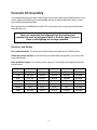
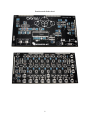
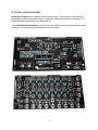
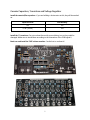
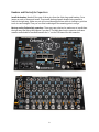
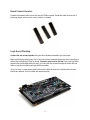
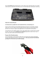
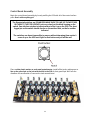
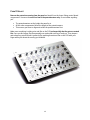
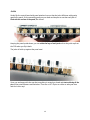
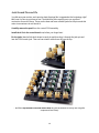
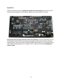
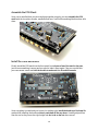
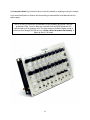
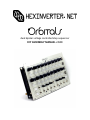
dual bipolar voltage controlled step sequencer DIY ASSEMBLY MANUAL v1.03 Contents Contents.......................................................................................................................................... 2 Introduction .................................................................................................................................... 3 Part Sourcing Notes for Non Kit Builders ...................................................................................... 3 Eurorack Kit Assembly.................................................................................................................... 4 Resistors and Diodes .................................................................................................................. 4 IC Sockets and Ferrite Beads...................................................................................................... 5 Ceramic Capacitors, Transistors and Voltage Regulator........................................................... 7 Headers and Electrolytic Capacitors .......................................................................................... 8 Board Connect Headers .............................................................................................................. 9 Logic Board Stacking .................................................................................................................. 9 Onto the Control Board! ............................................................................................................ 10 Prepare the Potentiometers...................................................................................................... 10 Control Board Assembly ........................................................................................................... 11 Panel Fitment ............................................................................................................................ 12 Jacks ......................................................................................................................................... 13 Jack Ground Pins and ICs......................................................................................................... 14 Install ICs................................................................................................................................... 15 ................................................................................................................................................... 15 Assemble the PCB Stack .......................................................................................................... 16 Install the Panel and Knobs ...................................................................................................... 16 2 Introduction Thank you for your interest in/purchase of a hexinverter.net Orbitals step sequencer! It is my hope that you find this module design a fun addition to your modular synthesizer. This assembly manual will show you how to build your Orbitals module in the eurorack modular format. This project is designed as a eurorack module and thus there are no provisions made for other formats. While possible to adapt it to your own format if you know what you are doing, it will be a lot of work! Assembling this module in eurorack form requires basic electronics knowledge and soldering ability. If you do not yet have these skills, go practice on some easier projects first! I link to some excellent soldering tutorials in the DIY learning resources section of my project site. A huge thank you to Hannes Pasqualini of papernoise.net for his excellent graphics design and artwork used for this project! (http://papernoise.net). As always, please email me with any tech support or questions you may need answered. I can be reached directly via email at hex[at]hexinverter.net Please read on! --Stacy Gaudreau hexinverter.net Electronics Part Sourcing Notes for Non Kit Builders IF YOU BOUGHT A KIT FROM HEXINVERTER.NET, SKIP READING THIS! Orbitals is designed primarily as a kit product to make things easy for people to get parts. While I do provide a Mouser project cart and a Bill of Materials, it is more challenging to do things that way as some of the parts have to be found at very specific places and not all parts can be purchased from one supplier. Of course if you stock electronic parts and are a seasoned builder, you should have no problem finding what you need! Right now, I know of no carrier of the momentary reset button (there is one needed to build the module). The Mouser project contains all latching push buttons. So, the reset button will therefore be latching. Still functional – but perfect? Probably not, depending how you like a master reset button to work. So, with this in mind, make sure you go through the entire Google spreadsheet Bill of Materials (linked to off the project site) and make sure you read the notes about each part before you dive into ordering things! 3 Eurorack Kit Assembly I recommend following the steps outlined here if you haven’t built many modules before. If you are an experienced builder, you could probably just give a read through these steps to catch any possible traps ahead of time. We’re going to be assembling both of the PCBs at the same time, so get your tools and parts ready and let’s go! Save your component lead clippings from the resistors and capacitors to reuse as jack ground wires in the later steps! Try to cut them so the clippings are as long as possible. Resistors and Diodes First, install the diodes. The band on the diode matches the band on the PCB silkscreen. Diodes are polarity sensitive. It is critical that you install them the right way or the circuit will not work properly! Next, install the resistors. The resistor colour codes for 1% metal film (as supplied in the kits) are as follows: 330R ORANGE ORANGE BLACK BLACK BROWN 1k BROWN BLACK BLACK BROWN BROWN 1.5k BROWN GREEN BLACK BROWN BROWN 4.7k YELLOW PURPLE BLACK BROWN BROWN 10k BROWN BLACK BLACK RED BROWN 43k YELLOW ORANGE BLACK RED BROWN 86.6k GREY BLUE BLUE RED BROWN 100k BROWN BLACK BLACK ORANGE BROWN 4 Resistors and diodes done! 5 IC Sockets and Ferrite Beads Install the IC sockets, being careful to orient them correctly. I find it easiest to put a book or something else flat on them once they’re installed, then flip the board over for soldering. This keeps them nice and flat while you solder them in. Then, install the two ferrite beads. They look like grey cylinders and are located near the power connector. The direction they are installed in does not matter. 6 Ceramic Capacitors, Transistors and Voltage Regulator Install the ceramic/film capacitors. If you are building a hexinverter.net kit, they will be marked as: Capacitor Value Case Marking 1nF 102 0.1uF (100nF) 104 Install the 11 transistors. Do not overheat them with your soldering iron or they could be damaged. Make sure to install them according to the orientation of the PCB legend! \ Bend over and install the 7805 voltage regulator. Careful not to overheat it! 7 Headers and Electrolytic Capacitors Install the headers. Break off four sets of three pins from the 40pin long male headers. Put a jumper on each of these and install. Then install the keyed power header, being careful to orient it the right way. Solder one pin at first and then adjust them while re-heating to get them to sit nice and straight! Then you can finish soldering all the remaining pins in one go. Next up are the 5 electrolytic capacitors. These guys are polarized so make sure to install them the right way! Bad things will happen if you don’t. The black band on the capacitor indicates negative and should be installed opposite the “+” on the PCB legend for that capacitor. 8 Board Connect Headers Prepare the headers that connect the stack of PCBs together. Break the male sections off of the longer 40pin sections with a pair of pliers or clippers. Logic Board Stacking Connect the two boards together using the three header assemblies you just made. Begin soldering by tacking only one or two pins in place and spending some time inspecting to ensure that everything is lined up nicely. You don’t want to screw this up! If you can’t get them aligned nice and straight with your eyes, you can stick the screws through the holes and use them to help line everything up right while you solder. Once you have a couple points held in place with solder and you are confident that the two boards are aligned, you can solder the remaining pins! 9 Now, very carefully take the boards apart. Do just a bit at a time, alternating sides. You do NOT want to just try to yank them apart all at once, or you might bend pins and damage something! Onto the Control Board! It is almost time to assemble the control surface! But first, I recommend you to: Look over the two PCBs you just populated and make sure there are no missing or shorted solder joints. You don’t want to put it all together and then find out you missed a few spots with the iron! It becomes a pain to take apart after the control board is all assembled. If you have been up for awhile working on this or feel rushed, take a nice break and come back to it later. This is for sure the hardest part of assembly and you don’t want to mess it up. So have a fresh, well-rested mind for this final section. Prepare the Potentiometers The 18 metal shaft pots all need their locking clip cut off. Grab a pair of sharp cutting pliers and clip off the little tab of metal on each pot, as shown. Wear eye protection! These little bits go flying off in all directions very fast when clipping. 10 Control Board Assembly Begin the control board assembly by loosely stuffing the PCB with all of the control surface parts. Don’t solder anything yet! The illuminated switches are POLARIZED! MAKE SURE TO LINE UP THE NOTCHES ON THEM TO THE PCB LEGEND! Look very closely at the black housing on the switch. One side has notches to indicate where to line it up on the PCB. The short legged pin on the switch should also be on the notched side, so that’s another indicator! The switches are almost impossible to remove without damaging them so don’t screw it up or the LED won’t light for that button and you will be sad! Place a white plastic washer on each metal potentiometer. Install all the jacks, making sure to line up the ground pin on the jack with the hole in the PCB for that ground pin. We’ll use the clippings you saved earlier to connect the jack grounds later! 11 Panel Fitment Remove the protective covering from the panel and install it on the loose-fitting control board components. Screw on the nuts for a few of the potentiometers only. Do not solder anything yet! The potentiometers set the height the panel is at. All the other components follow the height of the potentiometers. This means you have to align and solder the potentiometers first. Make sure everything is sitting nice and flat on the PCB and especially that the pots are seated flat. Once you are happy, flip the assembly over and solder one leg of each pot. Then inspect and reheat any pots that aren’t perfectly flat, pushing them down flat on the PCB with your finger while you reheat the one leg you soldered. 12 Jacks Gently flip the control board with panel attached over so that the jacks fall down with gravity against the panel. Sit the assembly gently on your desk and inspect to see that each jack is flush with the surface of the panel, like shown: Keeping the panel upside down, you can solder the legs of each jack so that they stick up from the PCB when you flip it back. The jacks all stick up against the panel now! Once you are happy with the way that everything is seated, go ahead and start soldering all the pins of the potentiometers and switches. There are a LOT of pins to solder so take your time and don’t miss any! 13 Jack Ground Pins and ICs You did save your resistor and capacitor lead clippings like I suggested at the beginning, right? Well, now it’s time to put them to use! The Kobiconn jacks require you to run a ground connection for each of them. These are the best and most suitable jacks for the price and this minor inconvenience is well worth it! Carefully remove the panel from the control PCB assembly. Install the 4 ICs in the control board now, before you forget later! For the jacks I bend a little hook shape in each pin and then drop it through the jack pin and into the PCB for each jack. Then you can simply solder them all from the top: …and then flip the board over and solder them all from the bottom as if they are a regular component lead. Easy! 14 Install ICs Almost there! Now it’s time to install the rest of the ICs in their sockets. Bend each row of IC legs in by bending lightly on a flat tabletop. Make sure to orient them all correctly! Now you are done the actual electronics part of the assembly! I highly recommend going over all of the backs of the PCBs one more time and making sure there are no shorts or missed soldering points. Once you put the PCB stack together and the panel on, it’s pretty daunting to have to take it all apart again to fix a mistake. So, do it right the first time by checking your work over now! 15 Assemble the PCB Stack Once you’re satisfied that you put everything together properly, you can assemble the PCB stack with the 4 machine screws, standoffs and nuts. It will look something like this when all is done: Install the Panel and Knobs Finally, install the PCB stack into the front panel, but only use a few of the nuts for the pots, just in case something is wrong and you need to take it apart again. Plug your module into your case power supply and test the module to make sure it’s all working properly. Once everything is tested and you’re sure it’s working right, install the knobs as a final step! Be gentle while installing the knobs and don’t push them all the way down. Carefully adjust them near the end so they are at the right height and don’t rub on the nut when turned. 16 And now you’re done! Yay! You don’t have to tune this module or anything so plug it in and go! If you need clarification on how to use the module, go download the User Manual from the project page. NOTE: On the DIY build here, unfortunately a little hardware bug made it into the production PCBs. I have no idea how I missed it but the BIPOLAR switch LED doesn’t light up if the jumpers are in 5V range mode on the back. Bipolar mode is still active even though the LED isn’t, so it doesn’t affect the module functionality. It lights up fine in 10V mode. 17