1
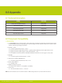
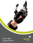
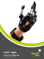
i-limb digits
Clinician Manual
TM
Part number: MA01064: Issue No. 1, December 2012
This document provides instruction for prosthetists in the fitting and servicing of i-limb digits and
should be read in full prior to fitting. It is highly recommended that the use of this manual is made in
conjunction with instruction from a clinician experienced in the use of i-limb digits.
This symbol signifies important information and is used throughout the manual.
Refer to www.touchbionics.com to ensure the latest copy of this document.
Part number: MA01064: Issue No. 1, December 2012
2
Table of Contents
i-limb digits
1.1
1.2
Patient Selection
1.3
Fitting Process
1.4
Control Site Options
Wristband and Battery
2.1
Wristband
2.2
Battery
2.3
Battery Charging 2.4
Storage and Maintenance
biosim 3.1 biosim Overview
3.2 biosim Connecting
3.3
Navigating biosim
3.3.1 Myo-testing
3.3.2 Control Strategy
3.3.3 Features
3.3.4 Training
3.3.5 Hand Health Check
3.3.6 Usage
3.3.7
1
Product Description
2
3
Exit
4
Covers
4.1
5
Adjustments
5.1 6
Support Information
6.1
6.2
Troubleshooting
6.3
Warnings and Precautions
7
User Information
7.1
User Details
8
Appendix
8.1
Technical Information
8.2
Component Compatibility
8.3
Warranty
Part number: MA01064: Issue No. 1, December 2012
Cover Options
Adjustments
i-limb digits with Full Forearm Socket
3 of 40
1.0 i-limb digits
1.1 Product Description
i-limb digits is a highly individualized, externally powered, multiarticulating prosthetic device offering functional enhancement of
the partial hand.
Individually motorized digits work in conjunction with available
anatomy to improve functionality. i-limb digits is externally
powered and offers compliant grip through individually powered
digits with stall out ability. A manually rotating thumb, when
required, in conjunction with vari-grip, auto-grasp and the wide
range of automated grip patterns lead to broad functionality.
Users can choose from a wide selection of automated grips
and gestures to help complete daily tasks, depending on i-limb
digits configuration. Grips and gestures can be customized
further for precise control.
The Wristband design enables the range of movement at the
wrist to be retained, while providing an open forearm to reduce
the build-up of heat and associated sweating. Hand control sites
provide a reliable electrode position facilitating the Wristband
option.
1.2 Patient Selection
i-limb digits is appropriate for patients with partial hand loss or
deficiency; where the level of loss or deficiency is:
• Distal to the wrist
• Proximal of the metacarpo-phalangeal joint
Devices are suited to patients with any 3, 4 or 5 digit loss, while
patients with 1 or 2 digit loss are also indicated when the digits
of loss are either the thumb or the main digits of opposition,
namely the index and middle fingers. (i-limb digits devices
have been used successfully outside of the above guidance).
i-limb digits is not indicated for patients with:
• insufficient hand loss or deficiency, as outlined above
• cognitive impairment, such that the device is unable to be
controlled
• where skin integrity is insufficient to support a prosthetic
device
Part number: MA01064: Issue No. 1, December 2012
4 of 40
1.3 Fitting Process
During the patient assessment stage consideration should be given to socket design. Standard prosthetic fitting factors including
skin/socket interface, suspension of the prosthesis and donning/doffing, must be considered. Additional factors specific to i-limb
digits include control site location and digit positioning.
After possible control sites have been identified and the most appropriate sites selected, an impression of the patients’ residual
limb can be taken. Initial control site training can commence prior to fitting of the check socket. The check socket should be fitted
and assessed for fit, comfort, suspension and donning/doffing. Appropriate location and electrode or FSR contacts should be
determined. Any necessary alterations should be made prior to progressing.
Digit positioning takes place on the check socket to create a prototype prosthesis. During digit positioning a range of sizes and
shapes of objects can be used to assess the optimal position with particular attention to opposition of digits, span of opening and
coordination with any other remaining fingers.
Basic Functional Therapy Training is carried out. During this stage the prosthetist should determine that the prototype prosthesis
is optimized throughout a range of patient activities and ADLs. Any necessary changes should be made. biosim can be used
throughout the fitting process to individualize the device. The definitive prosthesis fabrication can commence when the optimal
prototype device has been achieved.
Intermediate Functional Therapy Training continues, again using the prototype device. At this stage biosim can be used to
individualize the device. Once fabricated, the definitive socket can be tested for fit and function. Advanced Functional Therapy
Training continues with the patient now using the i-limb digits prosthesis in real life situations.
Assessment:
establish patient
requirements, set
expectations, input
site selection,
impression taking*
Input site training
Clear silicone check
socket fitting
Basic functional
therapy training
Digit positioning
Input site confirmation
on check socket
Intermediate functional
therapy training with
prototype prosthesis
Definitive prosthesis
fitting
Advanced functional
therapy training with
definitive prosthesis
* Refer to livingskin training manual MA01031 and livingskin Impression Field Guide MA01042
consult i-limb digits training slides and training materials for more detail
Part number: MA01064: Issue No. 1, December 2012
5 of 40
1.4 Control Site Options
i-limb digits devices are controlled by using either Remote
Electrodes, FSR’s (Force Sensing Resistors) as illustrated, or
Standard Electrodes (see Section 6) for upper limb prostheses.
Electrodes and FSR’s are positioned within the hand socket.
Review i-limb digits Component Assembly Guide (MA01073)
for more information on assembly and fabrication.
For information regarding the fitting of Standard Electrodes,
review Manual MA091091, provided with the Standard
Electrode or via the Touch Bionics website.
Do not rely on previous myo-electrical testing.
Use anatomical sites where the electrode will
maintain constant, even contact with the skin. Avoid
placing electrodes near socket interface trimlines,
bony areas, skin grafts or fatty tissue.
Electrode Site Selection
The three regions within within the hand are:
1. Hypothenar compartment
2. Thenar compartment
3. Dorsum of the hand
Consult section 5 for information on myo-testing within biosim.
Consult i-limb digits training slides for more information.
Part number: MA01064: Issue No. 1, December 2012
6 of 40
Each region should be tested for viability. Special note should be made with regard to the thenar compartment, this is not a usable
control sites when the thumb is present and functional. Once all three control sites have been assessed follow the flow chart below
to aid prosthesis design.
Start
No sites
Q1 and Q2
Yes
Silicon forearm
socket
No
3 sites
1 site
2 sites
Determine number of input sites present within the hand
Q1 and Q2
Yes
Wristband
Single Site
No
Q2
Yes*
No**
Wristband
Dual Site
Q1: Is the input site the thenar eminence?
Q2: Is the thumb present and functioning against prosthetic fingers?
* Choose dorsal interossei and hypothenar compartment
** Select any two muscle groups
A check socket should now be created as a final check of appropriate control site placement. If there are inadequate control
sites for the creation of an i-limb digits device with Wristband, it is possible to create a device using a full forearm socket (more
information is provided in section 6).
Part number: MA01064: Issue No. 1, December 2012
7 of 40
2.0 Wristband and Batteries
2.1 Wristband
The i-limb digits Wristband has a circumference range of
155mm (6”) to 270mm (10.5”) and is positioned approximately
50mm (2”) proximal of the wrist joint, depending on anatomy.
If a larger Wristband is required, an extension piece can be
added (contact Touch Bionics to discuss your needs).
The i-limb digits Wristband contains the PCB and two
removable 3.7V batteries. It is connected to the socket and
frame by a flexible sheath containing the wiring.
2.2 Battery
i-limb digits is powered by 800mAh, 3.7 Volt batteries which
have been specifically designed to meet the power requirements
of i-limb digits devices. Four batteries are provided, two for the
Wristband and two spares.
Two 3.7v batteries will be needed with the Wristband (the
Wristand will not work with only one battery).
Part number: MA01064: Issue No. 1, December 2012
8 of 40
76mm
(3”)
45mm
(1.75”)
95mm (3.75”)
58mm (2.3”)
Maximum
Minimum
The Wristband is switched on and off via the grey button on the
central panel. The light sequence is as follows:
On : Red light appears for 8 seconds
Off : Red light brief flashes
Low power: Green light flashes continually when the charge level
falls below 5%
Batteries are fitted into the Wristband battery housing and
secured by the holding catch at the wrist side of the Wristband.
Release the holding catch to remove the battery.
The batteries provided are designed to work specifically
with the Touch Bionics i-limb digits Wristband and are
not to be used with any other device.
Only Touch Bionics batteries are approved for use
with i-limb digits, use of alternative batteries will
invalidate the warranty.
Part number: MA01064: Issue No. 1, December 2012
9 of 40
2.3 Battery Charging
Batteries for i-limb digits should only be charged using the
Touch Bionics powerpack and battery charger supplied (UK,
European and US style plugs are available). Place the batteries
in the charger as illustrated. Insert the charger lead from the
battery powerpack into the charge port. Insert the charger into
the power outlet.
Charging time from full discharge is approximately 2 hours.
A continual blue light indicates that the battery is charging.
When the battery is fully charged the light will go out.
If a continual red light appears for more than 10 minutes then
the battery should be replaced.
Only use the plug to disconnect the charger, never
pull the cable to remove the lead.
Part number: MA01064: Issue No. 1, December 2012
10 of 40
As an alternative to charging directly from domestic power, a car
charger (PL069380A) is also available.
2.4 Storage and Maintenance
Always turn off the hand when not in use.
Aim to charge the battery each day after use.
Replace the battery every 12 months.
Part number: MA01064: Issue No. 1, December 2012
11 of 40
3.0 biosim
3.1 biosim Overview
The i-limb digits device is fitted with a Bluetooth® receiver
enabling it to work with software package known as biosim.
biosim-pro is the clinician’s version of biosim and biosim-i
is the version designed for patient users. Using biosim-pro it
is possible to make radical changes to the functionality of the
i-limb digits device. biosim-i is the patient user version of
biosim and contains a simplified version with access to training
and games, features along with some basic changes to settings.
The biosim software, working through the Bluetooth® wireless
connection, provides access to a range of control options,
training features, real time display of input signals, battery status
and health check.
understand and be comfortable working with the technology,
being able to make appropriate adjustments.
To use the biosim software with the i-limb digits prosthesis
you will need either an iPod touch supplied by Touch bionics
and preloaded with the biosim App, or a PC loaded with
the biosim software and used with the biosim Bluetooth®
dongle (the system requires either Window XP, Windows Vista
or Windows 7; Microsoft.NET framework v3.5; USB port for
Bluetooth® connector and administrative rights to install the
software and connector). Users of biosim via an iPod touch
are directed to iPod Touch with biosim App: Quick Start Guide,
provided with your iPod touch (also downloadable from www.
touchbionics.com).
While working with the patient user, an assessment should be
made of their suitability to work with biosim. Patient users must
3.2 biosim Connecting
biosim can be downloaded and access rights set up via http://
www.touchbionics.com/Biosimdownload. Once downloaded
open biosim by clicking on the biosim icon which should be
clearly visible on the screen. The biosim Handshake dongle
must also be inserted into a USB port to allow the Bluetooth®
signal to be received by the i-limb digits device. The Handshake
Bluetooth® receiver will connect within a 3 meter range and will
remain connected up to approximately 10 meters.
The opening welcome screen will load and the first numerical
icon “insert handshake” request will flash. On insertion of the
Bluetooth receiver (biosim dongle) the icon will be constantly
lit, the “handshake installed and ready” box will then self-tick
and the second icon “Turn device off, then back on” will begin
to flash. At this point the i-limb digits device should be turned
off and then on. The second icon will now be constantly lit and
the third icon “Connecting to device” will flash. The tab market
“connect” must now be clicked for the connection to be made,
this may take up to 24 seconds.
Part number: MA01064: Issue No. 1, December 2012
12 of 40
If there is more than one device (either i-limb digits, i-limb
ultra or virtu limb) within range of the Bluetooth® receiver
then a box will appear listing all devices by serial number. In the
illustration only one device is listed. The correct i-limb digits
device can then be selected from the list. For devices using the
Wristband, the serial number is located in the battery housing
on the main body of the Wristband, as illustrated. For devices
using the full forearm socket, the serial number is located on
the PCB which may be accessed using a zipped opening in
the socket. Additionally, a label will have been provided with the
initial component kit and should be added in an easily visible
location on the device. The serial number should also be added
to the patient notes and highlighted to the patient.
Part number: MA01064: Issue No. 1, December 2012
13 of 40
On opening biosim and linking to the i-limb digits device for
the first time a response box will appear on the opening page
requesting to run the configuration wizard (1). The configuration
wizard allows the software to learn the wiring order for the digits
and will follow the sequence outlined below.
Once the information has been input the software will guide the
user to the Digit Mapping screen (4). On starting the routine
the user is prompted to enter which digit moves in turn as the
software works through each of the digits (5).
An option for input selection is also provided (6).
Follow the prompts (2) and then input the digit size for each digit
in turn (3). The drop down box will also allow a “not present”
selection, indicating where the patient has an intact finger rather
than mechanical digit. The size can be found on the base of the
digit.
On completion the wizard will request input types for each
channel.
The Digit Configuration Wizard can be revisited at any time from
the Control Strategy screen, via the i-limb digits tab on the right
hand side of the screen (8).
1
2
3
4
5
7
Part number: MA01064: Issue No. 1, December 2012
6
8
14 of 40
3.3 Navigating biosim
The You’re now connected home screen will now be displayed,
with seven options as illustrated. This is the homepage and can
be accessed at any time from subsequent pages.
Myo-testing icon provides a quick and easy control site test
along with a more detailed analysis screen.
Control strategy details the choice and information around the
range of control options as well the logging of user information.
Features allows the set-up of the i-limb digits and is where
triggers are linked with with grip patterns and gestures.
Training provides access to the training suite and a selection of
games to improve overall control.
Hand health check icon provides a quick and easy diagnostic
check of the hand.
Usage icon provides access to a tally of individual movements
with additional analysis.
Exit icon draws the session to a close, exiting the program.
Part number: MA01064: Issue No. 1, December 2012
15 of 40
3.3.1 Myo-testing
The Analog gauges opening myo-testing
screen provides a very quick and easy
method of testing control site activation. The
strength of open and closed signals will be
illustrated on the gauges – the maximum
reading will be left as a shadow on the gauge
and the actual figure is provided below each
scale.
The Real-time graph screen plots a graph of the signal in
real-time, with open signals in red and closed signals in blue.
The choice of either open or closed input channels is offered,
providing the option to make the signal curve invisible by
unticking the Visible box at the top left of the screen.
Gain and Threshold levels are indicated, pre-set values being
70% for gain and a threshold level of 0.2V. Either can be
modified depending on the needs of the user. On changing
the threshold levels and the top of the screen the level is
automatically changed on the graph.
The graph can be paused, restarted, saved or enlarged using
the control and the bottom of the screen.
The graph automatically moves at a pace of 10 seconds per
page, however can be altered to a speed of between 2 and
60 seconds per page.
Training mode option enables training with specific triggers.
i-limb digits is optimized for use with electrodes where the
signal is set between the 1.5 and 2.5 area of the graph with
good differentiation between signals. If the gains are set to their
maximum or minimum, then the user may find it very difficult to
control the i-limb digits device.
Start/stop
graph
• If the gain in electrodes is set too high, the electrode may
pick up extraneous noise signals and transmit them to the
hand, causing unintentional operations of the hand. Also,
the window to achieve proportional control is narrowed
significantly and makes it very difficult to achieve slower
precise movements.
• If the gain is set too low, then the user may complain that it is
too difficult to operate proportional control.
The optimal electrode sites are where the user is able to
generate the greatest difference between the two electrodes.
The user must be able to separate the signals.
Part number: MA01064: Issue No. 1, December 2012
16 of 40
Save graph
Rewind
View Saved
Graph
Zoom in
Clear graph
Zoom Out
3.3.2 Control Strategy
The control page provides access to control
strategy settings. Control strategy is the
method by which the i-limb digits device
responds to the input signals. While superior
control of i-limb digits is possible with a dual
site strategy, it is possible to control i-limb
digits with a single electrode or FSR when a
second site is not possible. Control strategy
can only be changed through biosim; further control strategies
for both dual and single site control are possible:
• Dual site Differential – the stronger of the two signals determines whether the hand opens or closes. As one signal becomes
stronger than the other the hand direction changes. This strategy allows for rapid switching between hand operations, there is
no requirement to fully relax the signals to change direction.
• Dual site First Over – the presence of a signal above the threshold level before its opposing signal will result in the hand moving
in the direction of the that signal. While the first over signal remains above the threshold it will have dominance over the opposing
signal – regardless of which is strongest. Signal dominance only changes once both signals drop below the threshold level. This
is a useful training strategy to develop signal separation.
• Single site Voluntary Close – the presence of a signal above the pre-set threshold level results in the hand closing. Any signal
below the threshold or removal of the signal will result in the hand opening.
• Single site Voluntary Open – the presence of a signal above the pre-set threshold level results in the hand opening. Any signal
below the threshold or removal of the signal will result in the hand closing.
• Single site Alternating – the presence of a signal above the pre-set threshold level results in the hand opening. The next signal
above the threshold level will result in the hand closing.
Re-grip time-out is used to allow for a margin of error when the individual is moving in one direction and relaxes but does not yet
want the hand to move in the opposite direction.
Auto-revert is the time after which the hand will automatically revert to a close signal regardless of whether or not the next
alternating signal would have been open. This prevents the user from dropping an item when they do not recall which signal
was the most recent.
1
The graph shows good separation of inputs with opposing
channel remaining below the threshold level.
Part number: MA01064: Issue No. 1, December 2012
17 of 40
2
Graph showing good separation between input signals,
however the blue, closing signal is flat lining at the top of
the graph – proportional control of the hand is diminished.
Reduce the gain setting on closing input.
3
Graph showing low signal strength.
Encourage patient to increase signal strength, increase electrode
gain if the patient is unable.
4
Poor signal separation with both signals being activated
together.
Select first over control strategy to encourage the patient to
activate one muscle group at a time. Ensure commands are
clear and the patient understands what is required and return
to basic control site training.
5
Excessive signal activity with both signals together.
Consider looking for alternative control sites, if the current
control sites are the best option then select a first over control
strategy, encourage the patient to relax signals and make
definite open and closed actions with relaxation of the opposing
muscles.
Part number: MA01064: Issue No. 1, December 2012
18 of 40
In the General tab of the control screen the Device information
box will indicate the i-limb digits serial number. An option
exists to swap input channels if the prosthesis has been wired
incorrectly; and to enter battery type.
The administrative tab allows for the addition of personal
information, the Patient Summary highlights user name and
identifier code. The session management allows for the saving
of the last training session and review previous sessions.
Session management provides an option to save the last
settings of the device. Setting can then be reloaded and
reviewed using the relevant icons. There is also an option to
return the device to factory defaults.
The Edit tab will lead to the Patient Wizard, allowing for
more detailed personal information.
Part number: MA01064: Issue No. 1, December 2012
19 of 40
3.3.3 Features
Click on the features icon to enter the features
suite. The feature page provides access to all
available features and associated changes.
Features are the actual movements of the
hand and triggers are the muscle action used
to create the movements.
The grip patterns illustrated are:
First row – 4 precision pinch options
Second row – 4 tripod grip options
Third row – 2 thumb park options, lateral grip and index
point options
Fourth row – custom gesture and custom grip options
Features Catalogue
Precision Pinch Grip Options
Standard Precision Pinch Opened
middle, ring and little finger remain fully
opened and switch off. Index finger and
thumb provide grip.
Standard Precision Pinch Closed
middle, ring and little finger automatically
close and switch off. Index finger and
thumb provide grip.
Thumb Precision Pinch Opened
middle, ring and little finger remain
fully opened and switch off. Thumb
automatically moves to a partially closed
position. Index finger will move to provide
grip against a fixed thumb.
Thumb Precision Pinch Closed
middle, ring and little finger automatically
close and switch off. Thumb automatically
moves to a partially closed position. Index
finger will move to provide grip against a
fixed thumb.
Tripod Grip Options
Standard 3 Jaw Chuck (Tripod) Opened
ring and little finger remain fully opened and
switch off. Thumb, index and middle fingers
move to provide grip.
Standard 3 Jaw Chuck (Tripod) Closed
ring and little finger move to terminal
close. Thumb, index and middle fingers
move to provide grip.
Thumb 3 Jaw Chuck (Tripod) Opened
ring and little finger remain fully opened and
switch off. Thumb automatically moves to a
partially closed position. Index and middle
fingers move to provide grip against a fixed
thumb.
Thumb 3 Jaw Chuck (Tripod) Closed
ring and little finger move to terminal
close. Thumb automatically moves to a
partially closed position. Index and middle
fingers move to provide grip against a
fixed thumb.
Part number: MA01064: Issue No. 1, December 2012
20 of 40
Additional Grip and Gesture Options
Thumb Park Continuous – all four fingers
remain open and switch off, only the thumb
will move.
Thumb Park Quick – all four fingers
remain open and switch off, for 1.5
seconds the thumb will close and then
automatically return to an open position.
Lateral Grip – all four fingers fully close
and switch off. Only thumb will move.
Index Point – thumb, little, ring and
middle fingers close and switch off. Only
the index finger will move.
Customer Gesture – all fingers
automatically move to a user defined fully
opened and fully closed position.
Custom Grip – all fingers automatically
move to a user defined position.
Additional Functioning
Toward the bottom right of the screen the additional Global
Options box can be used to give access to Vari-grip / pulsating,
Natural Hand and Auto-grap modes.
1
Vari-grip / pulsating: this mode provides additional grip
force with subsequent activation of the closed signal.
The default setting for activation is 500ms (0.5 seconds)
which can be customized between 250 (0.25 seconds) to
3,000ms (3 seconds).
Part number: MA01064: Issue No. 1, December 2012
21 of 40
2
Auto-grasp: this feature enables the user to counter a
false open signal during grasping. If a false open signal is
identified the grip of the hand is automatically closed around
the object. The option of High level activation ensure that
the device has detected a full stop grasp before activating
auto-grasp. Low level activation creates auto-grasp upon
any closed signal to the device.
Both of these modes can be completely turned off.
Triggers
A trigger is the stimulus sensed by the electrodes or FSR. Four potential triggers are available, Hold open, Co-contraction, Double
impulse and Triple impulse.
1
Hold open (a prolonged open signal), this is preset to
2,000ms (2 seconds) and can be customized from 2,000
to 5,000ms.
The graphs shows a good hold open trigger, the signal strength
is well above 1.0V and the signal duration is around 3 seconds.
Threshold level
Part number: MA01064: Issue No. 1, December 2012
22 of 40
2
Co-contraction is the creation of simultaneous open
and closed signals. Co-contraction may be customized
if a patient has difficulty with activation with the default
time. This is done by going to myo-testing and entering
co-contraction in the training mode drop down box. The
“Begin Calibrating” icon will then appear, on starting
calibration 4 successful attempts must be made at a cocontraction for biosim to create the parameter settings.
Part number: MA01064: Issue No. 1, December 2012
23 of 40
3
Double impulse (two open signals separated by relaxation
beneath the threshold) the impulse duration is the period
of time that the impulse is above the threshold. It is preset
at 300ms and can be customized from 30 to 3,000ms. The
impulse period, or period within which both impulses must
be completed to be recognized, is preset at 1,000ms and
can be customized from 500 to 3,000ms.
N.B. The hand must be fully open for the Double Impulse trigger
to be recognized.
The graph shows an optimal double impulse. Both impulses
are of sufficient strength to break the threshold, the first impulse
drops below the threshold to allow recognition of the second
impluse. Both impulses are activated within the preset impulse
period.
(i) The graph shows a failed double impulse attempt. The
impulse signals are sufficiently strong, however the impulses are
too far apart to be identified. Both impulses are recognized as
individual open signals.
Encourage the patient to perform the impulses close together.
Consider lengthening the impulse period.
(ii) The graph shows a failed double impulse attempt. The
double open signals are strong and within the preset impulse
period, however the presence of the blue, closed signal disrupts
the impulses.
Encourage the patient to relax the closed signal during double
impulse activation. Consider changes to gain and threshold
of the closed channel, depending on activation during other
activities. Consider a first over strategy – the signal would be
accepted using this strategy.
Part number: MA01064: Issue No. 1, December 2012
24 of 40
Impulse period
Impulse duration
(iii) The graph shows a failed double impulse attempt, using
dual site differential. The two open signals are sufficiently strong,
however there is no relaxation between impulses. The signal is
recognized as one open signal.
Encourage the patient to relax inbetween impulses.
4
Triple impulse (three open signals separated by relaxation
beneath the threshold) settings are the same as with the
Double impulse trigger. The impulse duration is preset at
300ms and can be customized from 30 to 3,000ms. The
impulse period is preset at 1,000ms (1 second) and can be
customized from 500 to 3,000ms.
The graph shows an optimal triple impulse. In a similar manner
to the double impulse, the three impulses are of sufficient
strength to break the threshold. The first and second impulses
drop below the threshold to allow recognition to subsequent
impulses. All three impulses are activated within the preset
impulse period (impulse period is not indicated on the graph).
N.B. The hand must be fully opened for the Triple Impulse
trigger to be recognized.
Once the trigger is linked to a feature the settings tab appears, providing the option to make changes to timings. In addition the
feature is now labeled with the relevent trigger. Any of the above four potential triggers can be linked with any of the above features.
Some users are able to perform activities of daily life (ADL’s) without the use of any triggers. In many cases users initially set one or
two triggers while familiarity and control is gained.
Part number: MA01064: Issue No. 1, December 2012
25 of 40
Linking Triggers with Features
In order to link a trigger with a feature simply click on to the
desired feature, the feature will now be highlighted. Select and
click the desired trigger which has been selected to link with
the highlighted feature. Both feature and trigger should now be
highlighted and the descriptive label will now appear under the
feature icon. The illustration indicates the Index Point Feature
linked to the Hold Open Trigger.
By left clicking any of the features on the features page the
available triggers and example sections will also appear. In order
to preview a feature simply highlight the feature and click on
example to the right of the screen. The section will then enlarge
and provide a demonstration of the feature. The hand Image can
be rotated to improve visualization by holding the left mouse key
and moving the curser in the direction of the intended rotation.
3.3.4 Training
The training suite contains a variety of short
training exercises aimed at developing control
of the i-limb digits device. The opening
screen highlights the series of exercises
which can be selected individually and in any
order. Both open and closed signals can be
practiced by selecting the appropriate box to
the right. Click on “Start” to start the exercise
and “Done” when the exercise is complete. An indication of
difficulty is provided by the 5 point scale on each module.
Part number: MA01064: Issue No. 1, December 2012
26 of 40
Strength Only focuses on generating a smooth strong muscle
signal without concern for the opposing muscle signal. This
exercise helps to strengthen the muscles.
Speed Only focuses on generating quick, strong muscle
signals. Do not be concerned about the opposing muscle in
this exercise.
Strength and Separation focuses on generating a smooth,
strong muscle signal while isolating the opposing muscle. This
exercise helps with separation of signals.
Co-contraction focuses on generating quick, strong
simultaneous contractions with both muscles. Do not be
concerned with relaxing after the contraction.
Part number: MA01064: Issue No. 1, December 2012
27 of 40
Hold Open focuses on generating a strong open muscle signal
and maintaining it at a high level for several seconds. Mastering
this exercise will enable use of the hold open trigger.
Speed and Separation focuses on generating quick, strong
muscle signals while isolating the opposing muscle. This
exercise lays the foundation for impulse control.
3.3.5 Hand Health Check
Hand Health Check screen provides a quick
and easy check of the hand. Click on the
“Run Hand Health Check” icon and the health
check will begin. There must be an internet
connection to run the Hand Health Check.
The i-limb digits device will then go through a series of
movements as each digit is checked, the process will run for
approximately 8 seconds and provide basic feedback on each
step.
Part number: MA01064: Issue No. 1, December 2012
28 of 40
3.3.6 Usage
The Usage suite provides usage information
on various measures of usage, including
power cycles (the number of times the hand
has been switched on), open / close cycle
and actual feature used.
Feature count gives the number of times the open
and closed command has been used with in a specific
grip pattern.
Excessive Signal Activity Count gives the number of
times the user maintained a signal above the threshold
level for more than 3 seconds.
Options to refresh and reset, along with saving and
illustrating the data are also provided.
This analysis is very useful when reviewing usage and
reliance on the various features of the i-limb digits
device.
3.3.7 Exit
Use the Exit icon to fully exit biosim.
Part number: MA01064: Issue No. 1, December 2012
29 of 40
4.0 i-limb digits Coverings
4.1 Cover Options
Silicone digit covers will be provided for the i-limb digits device.
Digit covers will be ready to fit and designed to cover each digit.
Touch Bionics’ approved digit covers must be used with each
digit of the device. The warranty will become void if the device is
used without an approved cover.
General Precautions
• The i-limb digits device must be used with approved Touch
Bionics’ digits covers.
• Never put more than one cover on each digit of the i-limb
digits device.
• Always use the digits cover designed for the i-limb digits
device.
• Ensure covers are fitted properly.
i-limb digits covers do not provide full protection from moisture,
oil, dust and dirt ingress. Caution should be observed.
Part number: MA01064: Issue No. 1, December 2012
30 of 40
5.0 Adjustments
5.1 Adjustments
For all information surrounding assembly or replacement of
digits, thumb or associated components refer to i-limb digits
Component Assembly Guide (MA01073).
Part number: MA01064: Issue No. 1, December 2012
31 of 40
6.0 Support Information
6.1 i-limb digits with Full Forearm Socket
In certain circumstances it will not be possible to create an
i-limb digits device with Wristband for a patient who fits the
initial selection, refer to Section 1.2. These reasons may be
because of:
1
A lack of availability, or inadequate control sites within the
hand.
2
The suspension cannot be achieved from a hand only
socket
In such circumstances an i-limb digits device with full forearm
socket can be fitted.
A device utilizing a full forearm socket will be compatible with
many of the i-limb digits components. However, a number of
differences will need to be appreciated:
1
Batteries will be fabricated into the forearm socket and will
be different from batteries which are used with the Wristand
outlined within this manual. Available batteries are 800mAh
or 1,300mAh. An alternative battery charger will also be
provided, along with an alternative battery charger.
2
PCB’s will be separate and will require fabrication within the
forearm socket.
3
Touch Bionics’ Standard Electrodes, PL091050B 50Hz
Electrode or PL091060B 60Hz Electrode should be used.
4
Wiring harnesses will also match the alternative battery and
PCB components.
A forearm socket would typically extend to approximately mid
forearm. A pouch within the silicone socket can be created to
locate the componentry (batteries, PCB, etc). This pouch can
be positioned according to the requirements of the patient,
often on the medial aspect of the forearm. Consideration should
be given in the design of the socket to suspension, fastenings
(zippers, straps, etc) and donning/doffing.
When using a forearm socket some of the benefits of the i-limb
digits device with Wristband will be lost. In particular, the
enhanced range of motion at the wrist; open forearm design
and easily accessible batteries for ease of charging.
Part number: MA01064: Issue No. 1, December 2012
32 of 40
6.2 Troubleshooting
Problem
Action
Prosthesis does not
operate
Ensure the prosthesis is switched on
Ensure the battery is connected
Ensure the battery is charged
Check that electrodes or FSR’s have good contact
Check that the Standard Electrode cable is installed correctly (grey side out)
One digit does not
operate
Exchange with an alternative working digit and re-check. Then contact Touch
Bionics
Check if the digit operates correctly using the Hand Health check in biosim
Prosthesis stops halfway
through an action
Check the battery cable is not damaged
Check that the i-limb digits screws are not loose
Check the electrode cable is not damaged
Electrode gain settings may be too high or too low
User complains that the
prosthesis is hard to
operate
Ensure the battery has good charge
Ensure that electrodes or FSR’s have good contact
Ensure the electrodes are well grounded
Ensure good electrode or FSR placement and wiring
Check electrode settings
Battery charge does not last
a full day
Fully charge the battery, this may take up to 2 hours
Check the battery connection
Ensure electrodes are not set above 5.5
Check user is not holding a sustained signal to the hand and check biosim user statistics
Replace with a spare i-limb digits battery
Prosthesis opens when a
close signal is provided
Switch the open and closed channels via biosim
Battery is not working
Check the battery is connected
Check the battery is charged
Check the device using one of the spare i-limb digits batteries
Part number: MA01064: Issue No. 1, December 2012
33 of 40
6.3 Warnings and Precautions
i-limb digits device
Batteries
Do not use without an approved cover
Do not bend or exert excessive pressure on the battery
Do not use under water
Do not pierce the battery
Do not use to operate heavy / industrial machinery
Do not disassemble
Do not use with machinery with moving parts that may
cause personal injury or damage
Do not expose to high temperatures
Users must comply with local regulations on the operation
of automobiles, aircraft, sailing vessels of any kind and any
other motorized vehicle or device
Do not use for extreme activities that may cause injury to a
natural hand
Do not expose to excessive moisture, liquid, dust, vibration
or shock
Do not incinerate batteries
Do not alter battery terminal wires
Do not short circuit the battery
Do not store batteries inside a vehicle
Dispose of batteries in accordance with US, European or
local regulations
Do not expose to high temperatures
Only use the appropriate Touch Bionics charger to charge
Touch Bionics batteries
Do not expose to naked flames
If the battery has visibly ballooned or swelled:
Do not use or expose to explosive atmospheres
• discontinue the charging process immediately
Do not disassemble componentry or modify in any way
• disconnect the battery
Maintenance, repairs and upgrades may only be performed
by qualified Touch Bionics technicians and technical
partners
• remove to a safe area
• leave and observe for 15 minutes
• replace the battery
Do not use with a damaged cover
• do not re-use
Damaged covers must be replaced or repaired by a qualified
Touch Bionics technician or technical partner
Only approved Touch Bionics accessories and tooling may
be used with the i-limb digits device
• dispose of any leaking batteries in an appropriate
manner
Failure to comply with the above guidelines will invalidate the
warranty.
A list of frequently asked questions will be provided to clinicians on request.
If you experience technical
problems with the i-limb digits
device call Touch Bionics as
follows:
Part number: MA01064: Issue No. 1, December 2012
34 of 40
North American Customers
(Canada, Mexico & US)
Tel:+1 855 MYiLIMB (694 5462)
UK & Non-North American Customers
Tel: +44 1506 438 556
Driving of Motor Vehicles
The i-limb device has the functional capability to assist a patient with driving a motor vehicle however due to factors including the
differences in world-wide driving regulations and the variations in the level of ability between patients Touch Bionics is unable to
provide definitive advice in respect of a patient with an i-limb device driving a motor vehicle.
Touch Bionics is aware that patients have used the i-limb to drive a motor vehicle and our recommendations prior to a patient doing
so would include the following:• contacting the driving authority in your home location to obtain and understand the local regulations;
• working with the appropriate authorities to have your car modified to meet the local regulations for your respective disabilities as
required;
• re-taking any mandatory driving test using your i-limb device to demonstrate your ability to operate a motor vehicle safely if
required by local regulations;
• contacting your insurance provider and advise them that you will be using the i-limb device to drive a motor vehicle;
• ensuring that the device has a fully charged battery. Please note that the i-limb device will emit a low battery signal which will
alert you if the battery requires to be charged;
• switching off the i-limb device. This is due to the possibility of involuntary muscle signals being generated; and
• moving the thumb into the lateral position to allow the i-limb to be removed from the steering wheel without opening the hand.
It is entirely the patient’s responsibility to seek confirmation that they are physically and legally able to drive using the device and
to the fullest extent permitted by law Touch Bionics shall under no circumstances whatsoever be liable to the patient or any other
party as a result of or in connection with a patient with an i-limb device driving a motor vehicle.
Part number: MA01064: Issue No. 1, December 2012
35 of 40
7.0 User Information
7.1 User Details
Provision of the following basic information will enable easy identification if the prosthesis is returned to customer service. Please
forward details to Touch Bionics as per the contact information on the back page of the manual.
User Name:
Fitting Date:
Hand Purchase Date:
Hand Serial Number:
It is recommended that the above information is also included in the patient notes.
Part number: MA01064: Issue No. 1, December 2012
36 of 40
8.0 Appendix
8.1 Technical Information
Activity
i-limb digits
Push up from wheelchair: full hand
80Kg/176lbs
Push up with one digit
20Kg/44lbs
Carry heavy bag full hand
100Kg/220lbs
Carry heavy bag one digit
25Kg/55lbs
Carry heavy bag on thumb
25Kg/55lbs
8.2 Component Compatibility
1. General Safety
1.1 The i-limb digits device is an electrical device, which under certain circumstances could present an electrical shock hazard
to the user. Please read the accompanying user manual thoroughly and follow directions stated in the manual to assure
maximum safety during charging and operation.
1.2 EN 60601-1:2006
1.2.1 Protection against electrical shock – Class II
1.2.2 Degree of protection against electrical shock – Type BF provides additional protection against electric shock
1.2.3 Degree of protection against ingress of water (IEC 60529:2001) – IP40
1.2.4 Not suitable for use in the presence of flammable anesthetic mixture with air or with oxygen or nitrous oxide
1.3 EMI/EMC
1.3.1 Compliance against standard EN 60601-1-2:2007
1.4 Radio Spectrum Matters (ERM)/Bluetooth
1.4.1 Compliance against standard EN 301 489-1 V1.8.1
1.5 EN 301 489-3 Clause 7.1
1.5.1 EN55022: 2006
1.6 Radiation emissions, Enclosure
1.6.1 EN 301-489-1 Clause 8.2 - Pass (30MHz to 6,000MHz)
1.7 Zones of Use
1.7.1 Not recommended in zones 0, 1, 20 and 21
N.B. See www.touchbionics.com for further information on EMC testing carried out on products within this manual.
Part number: MA01064: Issue No. 1, December 2012
37 of 40
Refer to operating instructions
Class II equipment – provides double Isolation to protect
against electric shock
Degree of protection – IP40
IP40
Protection against penetration by solid particles with diameters
larger than 1 mm. No special protection against penetration by
water
Batch/Lot/ID Number
For i-limb digits devices:
Each device has a guaranteed unique id number example:
0001:2012
The unique serial number for i-limb digits devices is a D with a
4 digit alpha / numeric number. The year of manufacture of the
device is then added.
WEEE Compliance
Catalogue number
Manufacturer
Keep Dry
1. Customer Service/Contact Information:
Touch Bionics, Unit 3 Ashwood Court,
Oakbank Park Way, Livingston EH53 0TH, UK
Touch Bionics, 35 Hampden Road
Mansfield MA 02048, USA
Tel: Customer Service: +44 (0) 1506 445 415
Tel: General Enquiries: +44 (0) 1506 438 556
Tel: +1 855 MY iLIMB (694 5462)
www.touchbionics.com
Part number: MA01064: Issue No. 1, December 2012
www.touchbionics.com
38 of 40
8.3 Warranty
Limited Warranty for i-limb digits
Touch Bionics warrants that the i-limb digits components will conform to its specifications and be free of defects in material and/
or workmanship for a period of thirty-six (36) months from the date of Touch Bionics invoice for i-limb digits components. This
Limited Warranty applies only to i-limb digits components provided by Touch Bionics or an accredited Touch Bionics provider.
This Limited Warranty applies to all components including but not limited to fixtures, motors, bearings, and electronics for the same
thirty-six (36) month period. This Limited Warranty is governed by UK law and is not transferrable.
Warranty:
Touch Bionics reserves the right to credit, repair or replace “in-warranty” i-limb digits components as its option. If required,
replacements will be new products. The wearer shall report any defect claim to Touch Bionics directly or to the facility that provided
i-limb digits components immediately upon discovering the defect, and, in any event, within the warranty period. The defective
i-limb digits component must be returned to Touch Bionics or any other Touch Bionics provider. To find the nearest location,
please search online at www.touchbionics.com or call +1-855-MY-iLIMB (US & Canada) or +44 (0) 1506 438 556 (International).
Wristband, digits, electrodes and wiring loom components must be returned as originally shipped.
The warranty is void if the i-limb digits component is subjected to abuse, neglect, alteration, modification, improper repair and/
or maintenance performed by anyone other than Touch Bionics or an accredited Touch Bionics provider. Damage as the result of
normal wear and tear including the result of fatigue is not covered during the warranty period. Damage resulting from installation of
parts and accessories not compatible with i-limb digits by anyone other than Touch Bionics or an accredited Touch Bionics facility
is not covered, including use of non-Touch Bionics batteries.
This is the exclusive remedy under this warranty, any and all other remedies that may otherwise be applicable are excluded,
including, but not limited to, incidental or consequential damages or punitive damages to the maximum extent permitted by law.
This is the only warranty made by Touch Bionics on i-limb digits components, and there are no warranties which extend beyond
the description herein. Any warranties that may otherwise be implied by law including, but not limited to, any implied warranty of
merchantability or fitness for a particular purpose are excluded.
This Limited Warranty gives the consumer specific legal rights. The consumer may also have other legal rights which vary from
country to country, from state to state in the U.S., from province to province in Canada and from state to state in Mexico. Some
countries and states may not allow the exclusion or limitation of incidental or consequential damages or warranties, so the above
limitations or exclusions may not apply to you. If it is determined by a court of competent jurisdiction that a certain provision of
this limited warranty does not apply, such determination shall not affect any other provision of this limited warranty and all other
provisions shall remain in effect.
Part number: MA01064: Issue No. 1, December 2012
39 of 40
North American Customers
(Canada, Mexico and US)
Touch Bionics
35 Hampden Road
Mansfield MA 02048
USA
Tel: +1 855 MY iLIMB (694 5462)
International Customers
Touch Bionics
Unit 3, Ashwood Court
Oakbank Park Way
Livingston EH53 0TH
Scotland
Tel: +44 1506 438 556
Email: [email protected]
For address details and further information
please visit www.touchbionics.com
Third party products and brand names
may be trademarks or registered
trademarks of their respective owners
© Copyright 2012 Touch Bionics Inc. and Touch EMAS Ltd. All rights reserved.
Issue No. 1, December 2012
Part number: MA01064