1
SW-2000M-CXP-80
User's Manual
SW-2000M-CXP-80
CMOS High Speed Monochrome
CoaXPress® Line Scan Camera
CXP 1.1 and 1.0
Document Version: 1.3
Date: March 13th, 2015
File: Manual_SW-2000M-CXP-80_First_Release_1.3.docx
1
SW-2000M-CXP-80
Notice
The material contained in this manual consists of information that is proprietary to JAI Oy,
Finland and may only be used by the purchasers of the product. JAI Oy, Finland makes no
warranty for the use of its product and assumes no responsibility for any errors which may
appear or for damages resulting from the use of the information contained herein. JAI Oy,
Finland reserves the right to make changes without notice.
Company and product names mentioned in this manual are trademarks or registered
trademarks of their respective owners.
Warranty
12 months from date of delivery, 4 months for repairs covering the work and parts at the
factory.
Certifications
CE compliance
As defined by the Electromagnetic compatibility requirements of Directive 2004/108/EC of the
European Parliament and of the Council, JAI Oy, Finland, declares that SW-2000M-CXP-80
complies with the following provisions:
EN 61000-6-2 (2005), EMC immunity
EN 61000-6-4 (2007), EMC emissions
FCC
This equipment has been tested and found to comply with the limits for a Class B digital device,
pursuant to Part 15 of the FCC Rules. These limits are designed to provide reasonable
protection against harmful interference in a residential installation. This equipment
generates, uses and can radiate radio frequency energy and, if not installed and used in
accordance with the instructions, may cause harmful interference to radio communications.
However, there is no guarantee that interference will not occur in a particular installation. If
this equipment does cause harmful interference to radio or television reception, which can be
determined by turning the equipment off and on, the user is encouraged to try to correct the
interference by one or more of the following measures:
- Reorient or relocate the receiving antenna.
- Increase the separation between the equipment and receiver.
- Connect the equipment into an outlet on a circuit different from that to which the receiver
is connected.
- Consult the dealer or an experienced radio/TV technician for help.
Warning
Changes or modifications to this unit not expressly approved by the party
responsible for FCC compliance could void the user’s authority to operate the
equipment.
2
SW-2000M-CXP-80
1
2
3
4
5
6
7
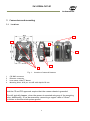
- Contents –
General .......................................................................................................5
1.1
Camera nomenclature ...............................................................................5
Main features ................................................................................................5
Connectors and mounting ..................................................................................6
3.1
Locations ...............................................................................................6
3.2
Connector panel and indicators ....................................................................7
Input and output ............................................................................................9
4.1
CXP BNC connector ...................................................................................9
4.2
CoaXPress® output modes ...........................................................................9
4.3
CXP revision ...........................................................................................9
Operation and functions .................................................................................. 10
5.1
Introduction .......................................................................................... 10
5.1.1 Image sensor ...................................................................................... 10
5.1.2 Line image processing ........................................................................... 11
5.2
Operating Modes ..................................................................................... 11
5.3
DSNU Corrector ...................................................................................... 11
5.4
Digital offset and gain stages ...................................................................... 11
5.5
Test Pattern Generator ............................................................................. 12
5.6
Flat Field Corrector, FFC ........................................................................... 13
5.7
Regions of interest, ROI ............................................................................ 13
5.8
Binning ................................................................................................ 13
5.9
Reversed readout direction ........................................................................ 13
5.10 CoaXPress® interface................................................................................ 14
5.10.1
Selection of the revision (CXP 1.0 or 1.1)................................................. 14
5.10.2
Link modes ..................................................................................... 14
5.10.3
ECT test modes ................................................................................ 14
5.11 Ethernet interface................................................................................... 15
5.12 Firmware updates ................................................................................... 16
5.12.1
MCU firmware update ........................................................................ 16
5.12.2
FPGA firmware update ....................................................................... 17
Command line interface .................................................................................. 18
6.1
Connecting via Telnet .............................................................................. 18
6.2
Entering the commands ............................................................................ 18
6.3
Command Format.................................................................................... 19
Description of commands ................................................................................. 20
7.1
Group A: General settings .......................................................................... 22
7.1.1 MODE – select camera operating mode ....................................................... 22
7.1.2 NET - network settings .......................................................................... 22
7.1.3 Saving and restoring the capture settings ................................................... 24
7.2
Group B: Commands affecting exposure ......................................................... 27
7.2.1 SENSOR – selects the sensor mode and analog gain ...................................... 27
7.2.2 LINE PERIOD and LINE RATE .................................................................... 28
7.2.3 LINE CTRL - Exposure Control .................................................................. 29
7.2.4 LINE IT - integration time....................................................................... 31
7.2.5 GAIN – digital signal gain........................................................................ 32
7.2.6 OFFSET - output offset .......................................................................... 32
7.2.7 FFC – flat field correction ...................................................................... 33
7.3
Group C: Commands affecting image output format .......................................... 34
7.3.1 CXP FORMAT ...................................................................................... 34
7.3.2 READOUT – pixel readout direction ........................................................... 34
7.3.3 ROI – regions of interest ........................................................................ 35
7.3.4 BINNING – paring of pixels ...................................................................... 36
7.3.5 ACQ – start and stop of acquisition............................................................ 36
3
SW-2000M-CXP-80
7.4
Group D: Utilities .................................................................................... 37
7.4.1 HELP or ‘?’ – list of commands ................................................................. 37
7.4.2 VER - camera information ...................................................................... 37
7.4.3 STATUS - camera information and settings .................................................. 37
7.4.4 TEST - test patterns ............................................................................. 37
7.4.5 REBOOT – restart the camera .................................................................. 39
7.4.6 FIRMWARE UPDATE – initiate the MCU update............................................... 39
8 Summary of commands .................................................................................... 40
9 Software tools for camera communications ........................................................... 44
9.1
JAI Sweep Ethernet Tool ........................................................................... 45
9.2
Internal web server ................................................................................. 47
10 External dimensions ....................................................................................... 48
11 Specifications ............................................................................................... 49
11.1 Operating range...................................................................................... 49
11.2 Common properties ................................................................................. 50
11.3 Performance per selected sensor mode ......................................................... 50
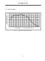
11.4 Spectral response .................................................................................... 51
12 Change History.............................................................................................. 52
4
SW-2000M-CXP-80
1 General
The JAI Sweep Series SW-2000M-CXP-80 is a CMOS line scan camera based on a custom-made
2048 pixel imager with large square pixels of 20 µm for high responsivity. It operates at a rate
of up to 80,000 scans per second.
The camera outputs digital data in 8-, 10-, or 12-bit formats, via one CoaXPress® (CXP) Link up
to 3.125 Gbps. The camera is configured via CXP interface using GenICamTM (a generic
programming interface for machine vision cameras) or via a 10/100 Mbps Ethernet port using an
industry standard RJ-45 connector.
The default lens mount is F-mount. Additional options will be added.
1.1 Camera nomenclature
The standard camera composition consists of:
SW-2000M-CXP-80 camera body with F-mount
Lens mount/sensor protection cap
x1
x1
In the model number of the camera, SW stands for “Sweep” Series, 2000 represents the
resolution “2000 pixels”, M stands for “monochrome”, CXP stands for “CoaXPress®” interface,
and 80 stands for “80 kHz” maximum scan rate.
2 Main features
•
•
•
•
•
•
•
•
•
•
•
•
•
•
•
CMOS line scan camera
Resolution: 2048 x 1
Pixel size: 20 µm, square
Selectable Quantum Well size: 60k or 360k electrons
Selectable clock rate for sensor
Maximum scan rate: 80,000 lines per second
CXP one link data interface
o One connector
o 8, 10, or 12 bits per pixel
o Supported CXP operating frequencies: 1.25G, 2.5G and 3.125G
DSNU correction as factory default
Flat field correction (FFC)
Test pattern generator for set-up and troubleshooting
Default lens mount: F-mount
DC input voltage via CXP cable
Ethernet port for
o Control and monitoring
o Firmware updates
o Download of files from camera (internal web server)
Short ASCII commands for set-up via Ethernet using the Telnet protocol
o Windows® user interface
TM
GenICam compatible
5
SW-2000M-CXP-80
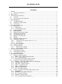
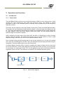
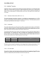
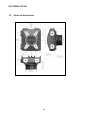
3 Connectors and mounting
3.1 Locations
64
3
2
1
6
4
6
4
Fig. 1. Location of external features
1
2
3
4
CXP BNC connector
Ethernet connector
Lens mount: Nikon® F-Mount
Mounting holes: all 8 pcs. are M5 with depth of 8 mm
Note:
Both the CE and FCC approvals require that the camera chassis is grounded.
This will typically happen, when the camera is mounted using any of the mounting
holes. Additionally, it can be secured by connecting a copper cable of 10 mm2
or thicker to the electrical system ground.
6
SW-2000M-CXP-80
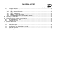
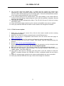
3.2 Connector panel and indicators
4
3
1
2
Fig.2.
Rear panel with the Ethernet connector cap on.
1. CXP LED
A multi-color LED with the following functions:
Orange (steady)
CXP is booting up.
Red (flashing slowly)
Power ON. Not yet connected.
/ Green/Orange (Flashing rapidly)
Connection detection in progress, PoCXP active.
Orange (Flashing rapidly)
Connection detection in progress, PoCXP not in use.
Green (steady)
Device connected, but no data is transferred.
Green (flashing rapidly)
Device connected. Data is being transferred.
Green/Orange (flashing slowly)
Connection test packets being sent.
Green/red/orange (flashing slowly)
Test mode for compliance.
Red (red pulse)
Error during data transfer.
7
SW-2000M-CXP-80
2. Status LED
A multi-color LED with the following functions:
Green (steady)
Normal operation.
Green (flashing slowly)
Busy.
Green (flashing rapidly)
Performing firmware update or waiting for a firmware update to start.
Orange (steady)
Initializing.
Orange (flashing rapidly)
MCU firmware update in progress.
Do not disconnect the Ethernet cable.
Do not switch off the power.
Red
Internal error
3. Ethernet Link LED
Green (steady)
Connected to an active network device. This indicates the existence of a physical
link only. It does not indicate a valid TCP/IP network configuration.
4. Ethernet Status LED
Yellow (flashing)
Activity indicator. Blinks shortly during data transfer.
8
SW-2000M-CXP-80
4 Input and output
4.1 CXP BNC connector
The CXP BNC connector connects to one, single, point-to-point, coaxial cable (75 Ω) to output
image data, communicate with the camera and to input power. Please refer to official standard
(www.coaxpress.com) for more information on the cabling solutions. Each cable connects all
the related grounds together: electrical zero of the internal electronics to the chassis of the
camera and then via the shielding of the cable to the electrical zero of the other end, which is
then often connected to system ground via its chassis.
4.2 CoaXPress® output modes
Bit depths of 8, 10, and 12 are supported. Camera operates internally with more than 12 bits.
All blanks are electrically zeroes.
4.3 CXP revision
The camera supports either revision 1.0 or 1.1. Default setting is for rev. 1.1. The revision can
be selected by writing to the CXP bootstrap register 0x4. The value 0x00010001 corresponds
with CXP1.1, while value 0x00010000 is written to use CXP1.0 after next boot-up.
The CXP revision value can be changed via CXP bootstrap registers or via virtual register (set 4
0x0001000x). This is a non-volatile parameter.
9
SW-2000M-CXP-80
5 Operation and functions
5.1 Introduction
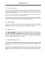
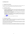
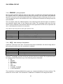
5.1.1 Image sensor
The SW-2000M-CXP-80 is built around a high performance CMOS line scan image sensor, which
converts the light collected by each pixel into electrical charge. The amount of charge
generated in each of the individual pixels is basically directly proportional to the amount of
light they receive.
The sensor has two options to store the charge at each pixel. These are called Quantum Wells.
The smaller well can hold about 60,000 electrons (60 ke-), while the larger has capacity for 360
ke-. The larger well should be used whenever feasible as it provides the best image quality due
to higher dynamic range and better signal-to-noise ratio (SNR), but also requires about six
times the light for the same response.
SNR is limited by the shot noise of the light itself and thus it is beneficial to collect as many
photons (light) as possible. The smaller well can be used to provide about six times as high
response to light, but with the cost of lower SNR and dynamic range.
Due to internal timings and processing there is one inactive period of 1 to 3 µs per each imaged
line, when the received light is not used. Thus, the maximum time the light generated charge is
integrated, is always slightly shorter than the line period.
Correlated Double Sampling (CDS) is used for sampling the charge voltage and the reset level
to find the difference, which is then digitized into more than 12 bits and sent out of the sensor
for processing. An analog gain factor of 2 can be applied to the above mentioned difference
regardless of the well size. The selection is included in the SENSOR command syntax.
-
e
SMALL
VOLTAGE
VOLTAGE
CDS
LARGE
PIXEL
QUANTUM WELL
COMMAND: SENSOR
Fig. 3.
Sensor block diagram
10
A/D
12½ BITS
SW-2000M-CXP-80
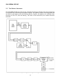
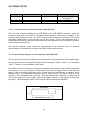
5.1.2 Line image processing
The output data from the imager is buffered for further processing to be then finally sent out of
the camera via the CoaXPress® interface. The processing chain is controlled by user accessible
commands. The DSNU corrector is calibrated individually for each camera at the factory and
always in use with fixed settings.
The scan rate and the integration of light within each line period can be controlled either by
the CXP trigger, internal timers, or a combination of these.
Serial communication channels are used to control and monitor the camera. Both the standard
CXP communication link as well as the Ethernet connection can be used for the same purpose
and even at the same time. Some functions are only supported via Ethernet.
5.2 Operating Modes
The camera can be configured to offer several operating modes that are fundamentally
different from each other. The operating mode is configured upon start-up and can only be
changed by issuing a new mode selection command and rebooting the camera.
5.3 DSNU Corrector
DSNU (Dark Signal Non-uniformity) describes the pixel-specific differences of response in dark,
while PRNU (Photo Response Non-uniformity) respectively describes the pixel-specific
differences of response to equal amounts of light falling onto all the pixels. Both are basic
sensor- and pixel-specific imperfections, which can be characterized and minimized. DSNU is
corrected already during production. Users may use the FFC function to further adapt the
camera into existing lighting conditions, if necessary.
5.4 Digital offset and gain stages
This block first shifts the digital pixel value up or down and then applies a digital gain. The
result is limited to stay between zero and the maximum digital value. Gain values lower than
the default 1x may cause the maximum output value to be lower than the maximum of the
range in use.
The offset block is a direct subtraction or addition. It does not define the target value for dark
response and has no feedback loop. That is why the gain block, which is simply a digital
multiplier, will also change the offset level, thus possibly causing a need to readjust the offset
value.
11
SW-2000M-CXP-80
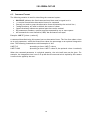
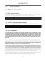
5.5 Test Pattern Generator
The SW-2000M-CXP-80 can send out five, defined test patterns instead of the real imaged lines
for purposes like interfacing and problem analysis. The patterns replace the image data and
can thus be used also to test the following blocks. Original, full patterns are available after
switching off the FFC, ROI and binning. Test data is also affected by the readout direction
selection.
Fig. 4. Image processing block diagram
12
SW-2000M-CXP-80
5.6 Flat Field Corrector, FFC
Factory calibrated DSNU corrector minimizes pixel-specific differences in darkness. There is no
use correcting the PRNU as a factory setting as it is less than the noise. Real applications only
rarely can provide equal amounts of light for all pixels. This is caused mainly by effects like
uneven distribution of light (light profile) or properties of lenses like vignetting. Pixels at the
center region tend to get more light, while the intensity decreases towards both ends of the
line image sensor.
The compensation method called Shading Correction results in a flat, equal response to light
under the same conditions in which the calibration routine was run. It is generally thought of as
a coarse correction to regionally scale or gain the pixel responses without paying attention to
any pixel-specific differences. Also, generally, a method called Flat Field Correction (FFC) is
used for operations where a similar correction is done more precisely and for each pixel
individually. The correction typically uses a 2-point linear method, where both the dark and
bright level pixel responses are equalized making it possible to have uniform response on all
light levels within the operating range of the camera. This would in fact be a complete, single
routine to perform DSNU, PRNU and Shading Corrections all at the same time, but the
corrections are separated in this implementation. DSNU correction is preset at the factory.
Shading correction is replaced by FFC, which operates assuming a fixed dark reference level
and includes the PRNU correction.
The FFC unit of SW-2000M-CXP-80 scales the pixel values by factors that are calculated by
imaging a calibration target in order to produce a uniform (flat) response under the same
conditions as where the calibration routine was run. A constant value (same as DSNU target
value) is used as the dark reference. Bright references are taken by averaging the lines that
were imaged from the calibration target.
5.7 Regions of interest, ROI
This block can be used to select up to four sections of pixels to be used as one combined line of
pixels. The purpose is to reduce the amount of data and to remove unnecessary regions.
5.8 Binning
Neighboring pixels can be digitally added or averaged as pairs. The resulting larger pixels are
then sent out as one. The resolution as well as the number of pixels will be half. The goal is to
have larger pixel area either to increase the response or to reduce noise.
5.9 Reversed readout direction
This function enables reading of the pixel values in correct order in cases where it is not
practical to install the camera to follow the intended imaging direction.
13
SW-2000M-CXP-80
5.10 CoaXPress® interface
CoaXPress® (CXP) is a communication standard for imaging applications. It provides high speed
image data, communications and control, triggering and power input all over a single coaxial
cable as one CXP link. The transmission is point to point and up to distances exceeding 100
meters. The so called Uplink for communications and control runs always at the constant rate
of 20 Mbps.
5.10.1
Selection of the revision (CXP 1.0 or 1.1)
The camera operates according to revision 1.1 as default, but supports also rev. 1.0. The
revision is selected by writing to the bootstrap register defined in the standard itself. The new
selection is automatically saved and taken into use at next boot up. The host should check the
setting during initialization and change it, if necessary.
5.10.2
Link modes
The camera always boots up at link speed of 3.125G to negotiate with the host on transmission
properties. The host is typically a frame grabber board and acts as the master here. It can try
any of the standard speeds or read the preferred link mode that the camera has been set to
show. The host then sets the camera to the mode it wants to use.
The preferred link mode of the camera can be preset to be one of the three options listed in
the table below. The command ‘cxp config’ is available only via the Ethernet connection as a
telnet command - not via GenICamTM. The given values are immediately saved, but will not
become effective until the next boot up. If the new mode is slower, please make sure that the
line rate value saved by the CS SAVE command is not too high.
Command
cxp config 1 1
cxp config 2 1
cxp config 3 1
Link mode
one link, 1.25G
one link, 2.5G
one link, 3.125G
Max. line rate. Use of ROI and BINNING may raise the limits.
The selected Operating Mode (see 7.1.1) is the absolute limit.
55/44/36 kHz for 8/10/12 bits
80/80/73 kHz
80/80/80 kHz
The host can then change the frequency of the image data link during the operation, if the
camera supports the new mode. The camera must follow the selections made by the host.
5.10.3
ECT test modes
The camera includes a special operating mode for the Electrical Compliance Tests (ECT) of the
standard. The camera will then output test mode data with the selected link speed. The new
values are automatically saved and taken into use at next boot up.
14
SW-2000M-CXP-80
5.11 Ethernet interface
The 10/100 Mbps Ethernet port interface is provided as an alternative way to communicate
with the camera. Connection to Ethernet offers usual networking possibilities like remote
access and connecting multiple cameras together for control and monitoring. The standard
GenICamTM programming interface via the CoaXPress® connection is allowed to be in use at the
same time. This of course requires caution, if both channels are used for changing camera
settings.
Firmware updates are loaded only via this interface. Standard web browsers can be used to
establish connections to the internal web server, which includes a few basic functions like
downloading of some documents and supporting updates.
This port can not be used for any actual image acquisition. Single lines (average of 32) can be
slowly read out and displayed as graphs by using the JAI Ethernet Tool software.
15
SW-2000M-CXP-80
5.12 Firmware updates
It is possible to update or change the camera firmware without opening the housing. New code
is loaded in via the Ethernet port and with help of web browser user interface. There are two
kinds of firmware updates: MCU and FPGA. The MCU (microcontroller unit) updates affect the
user interface and high level features of the camera, while the FPGA (field-programmable gate
array) updates provide enhancements for low level or hardware related functions.
The MCU update is first initiated by the command FIRMWARE UPDATE and then completed with
help of the user interface that opens up by accessing the main page of the camera web server.
The FPGA update is done by directly accessing the respective update page.
Caution: Ensure that the camera receives proper power during the complete firmware
update process. A power break can potentially leave the camera in a state, where it can
not start again.
5.12.1 MCU firmware update
1. Make sure you have the correct file (.hex) for the camera model and the existing
configuration available.
2. Make sure you have a working communication via the Ethernet port.
3. Make sure you have a compatible web browser and can access the main page at
http://10.10.10.10.
4. Check and make a note of the existing configuration (telnet command: VER).
5. Save any settings that you want to keep. The camera will reboot during the process.
6. Initiate the camera by telnet command FIRMWARE UPDATE. You may still cancel the
operation after this. Send command CONFIRM when asked, if you want to go ahead.
7. The CXP LED will turn orange and the status LED will start flashing rapidly. This
indicates that the camera is waiting for the new code.
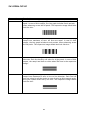
8. Access http://10.10.10.10 or refresh the page, if you already were there. The user
interface will let you browse for the new file (.hex) and upload it to the camera.
Fig. 5. User interface for MCU update.
16
SW-2000M-CXP-80
9. You can still cancel the update here, in which case the camera will reboot once
automatically. After a few short flashes, both LEDs turn into steady orange color. Wait
until the status LED becomes green and steady again. Close all communication sessions
to the camera and establish new ones as needed.
10. If you instead clicked on the upload button, the rapid flashing of the status LED will
continue with alternating orange and green colors until the upload is complete. Do not
interrupt the upload.
11. The camera will then automatically reboot. The LED will first go off, then turn orange
and finally green.
12. Close old communication sessions to the camera and establish new ones as needed.
13. Verify by command VER that the MCU version number has changed as intended.
5.12.2 FPGA firmware update
1. Make sure you have the correct file (.rbf) for the camera model and the existing
configuration available.
2. Make sure you have a working communication via the Ethernet port.
3. Make sure you have a compatible web browser and can access the main page at
http://10.10.10.10 .
4. Check and make a note of the existing configuration (telnet command: VER).
5. Save any settings that you want to keep. The camera must be rebooted during the
process.
6. Access http://10.10.10.10/FPGAupdate.html.
7. Browse and open the file (.rbf). You may cancel the operation now by closing the web
page. Click on Upload to proceed. Do not interrupt the upload.
8. Both LEDs will now turn off. The Ethernet status LED will blink during the upload.
9. Wait for the user interface page to change. This may take minutes. Then click on the
‘HOME’ button. The LEDs remain off.
10. The camera must next be rebooted. You may power cycle the camera or send the
REBOOT command followed by CONFIRM. No other commands should be sent before
this.
11. Close all communication sessions to the camera and establish new ones as needed.
12. Verify by command VER that the Logic version has changed as intended.
17
SW-2000M-CXP-80
6 Command line interface
The command line interface provides an easy, interactive way to control the camera. All
commands can be given through the Ethernet interface using the Telnet protocol.
6.1 Connecting via Telnet
To connect the camera using Telnet:
• Consult your IT department to check if you can plug the camera to your local area
network with the default IP address 10.10.10.10. You may change the address by using
the NET IP command. Alternatively, you may configure your network card to build a
direct connection to the camera.
• Connect the camera to a local area network using a twisted-pair cable. A shielded cable
of category 5 or higher is recommended.
• Open a Telnet client on the computer. Two options are available from JAI. Please refer
to chapter 9 of this document. Also free or commercial Telnet clients can be
downloaded from various internet sites. The following Telnet clients are examples of
clients tested with the Sweep cameras:
o Foxterm
o PuTTY
• Open a Telnet connection to the IP address of the camera.
6.2 Entering the commands
The commands are typed in the client console window like in any command line interface. A
carriage return (ENTER) terminates the command line and transmits it to the command
interpreter in the camera for parsing and execution.
If the communication is coded into a software application then each line must have a carriage
return character (ASCII: 0x0D) at the end. Also, a line feed character (0x0A) may be sent after
the carriage return, but it is not needed.
Please note that the response time of some commands is considerably longer. Commands like
VER, STATUS, CS LOAD, CS LOAD2 and CS FACTORY RESET take almost 10 seconds to complete.
18
SW-2000M-CXP-80
6.3 Command Format
The following notation is used for describing the command syntax:
•
•
•
•
•
•
•
BOLDFACE indicates the fixed command word that must be typed as it is
| A vertical line delimits alternative forms of a command
{braces} are used to group the alternative forms delimited by the vertical line |
<wedge brackets> are used to delimit the names of values
[square brackets] indicate an optional part that can be omitted
All parameters (numbers, options) must be separated by one or more spaces.
All commands are case insensitive; VER, Ver and ver are all equal
Example: LINE IT {<time>|<value>%}
A command described using this syntax has two alternative forms. The first form takes a time
as its only parameter, while the second form takes the percentage as an optional integration
time. The following commands are valid examples of this:
LINE IT 12
LINE IT 100%
(according to form: LINE IT <time>)
(according to form: LINE IT <value>%; the optional <time> is omitted)
When the command parameter is a physical quantity, the unit itself must not be given. For
example, the integration time is set to 12 µs but the microsecond unit is implied by the camera.
It must not be typed by the user.
19
SW-2000M-CXP-80
7 Description of commands
The commands can be divided into four groups:
Group A: General settings
MODE for selecting operating mode after boot-up.
NET for network settings for the Ethernet communication. The NET settings are saved
automatically.
CS SAVE, CS LOAD, CS SAVE2, CS LOAD2 and CS FACTORY RESET for saving, loading or
restoring the settings of group B and C.
Group B: Commands affecting exposure
SENSOR for setting sensor responsivity.
LINE RATE and LINE PERIOD for setting the scan rate.
LINE IT for selecting the actual light integration time.
LINE CTRL for selecting the trigger source.
GAIN for setting the camera gain.
OFFSET for setting the line offset value.
FFC for Flat Field Correction.
Group C: Commands affecting image output format
CXP FORMAT for setting the pixel depth.
READOUT for selecting normal or reverse readout direction.
ROI for selecting Regions Of Interest.
BINNING for combining adjacent pixels.
ACQ for start and stop of acquisition.
Group D: Utilities
HELP or ‘?’ for list of all commands.
VER for displaying firmware versions and camera identifiers.
STATUS to display camera information and settings.
TEST for selecting test patterns.
REBOOT for restarting the camera.
FIRMWARE UPDATE to change the MCU code.
20
SW-2000M-CXP-80
The four groups will be described in detail in the following sections. Most commands display
help on how to use it if a space and a question mark is added after the command, and current
status of the function if the command is entered as such with no parameters.
The general principle with all the group B and C commands is that users may experiment with
the settings without losing the latest, saved and working setup (exception: CS FACTORY RESET).
New settings are in use, but not permanently saved, until the user decides to save them. It is
always possible to return to the latest saved settings either by sending the CS LOAD, CS LOAD2
or REBOOT command or power cycling the camera.
NOTE:
The CS FACTORY RESET command also saves the new values to the first memory
location like the command CS SAVE.
21
SW-2000M-CXP-80
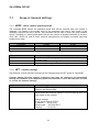
7.1
Group A: General settings
7.1.1
MODE – select camera operating mode
The command MODE selects the operating mode that will be entered when the camera is
rebooted. The names of the modes refer to the maximum line rate of each mode. If the
maximum required line rate is known, this command can be used to select the most suitable
option. Changing to a lower speed option may set the camera to operate internally at a slower
clock rate, which will lead to lower internal temperatures and slightly increased operating
temperature range.
MODE
SPEED40kL
SPEED70kL
SPEED80kL
Command
MODE ?
MODE
MODE <file name>
7.1.2
internal clock
60 MHz
100 MHz
100 MHz
max. line rate
40 kHz
70 kHz, factory default
80 kHz
Description
Returns the MODE setting syntax and a list of available modes
to select from.
Returns the present setting of MODE.
Sets a new operating mode. Reboot required.
NET - network settings
The Ethernet control interface settings can be changed using the NET group of commands.
Caution: Setting incorrect network properties can cause the camera to be unreachable
through the network. If this happens, please use GenICamTM via an SDK interface to reset
or correct the network settings.
Command
NET ?
NET
Description
Returns the NET settings syntax for manual/DHCP, IP address,
Gateway and Subnet Mask.
Returns the present setting of manual/DHCP, IP Address,
Subnet Mask and Gateway together with the settings after the
next reboot of the camera.
Default settings:
The IP setup mode is STATIC.
IP Address .... 10.10.10.10
Subnet mask ... 255.255.255.0
Gateway ....... 10.10.10.1
22
SW-2000M-CXP-80
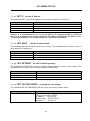
7.1.2.1
NET IP - set the IP address
The command NET IP sets the IP address of the camera. Default is 10.10.10.10.
Command
NET IP ?
NET IP
NET IP <xxx.xxx.xxx.xxx>
NET IP AUTO
Description
Returns the NET IP setting syntax.
Please use command NET for settings information.
Sets the camera to use a static IP address xxx.xxx.xxx.xxx.
Sets the camera to obtain a dynamic IP address using DHCP.
Caution: It is recommended to use a static IP address. If a dynamic address is selected,
there is no straightforward way to determine the address assigned by the DHCP server.
You may use GenICamTM via an SDK interface to search for the address.
7.1.2.2
NET MASK
– set the IP subnet mask
This command sets the IP subnet mask of the camera. The command has no effect in case of
using dynamic IP addressing.
Command
NET MASK ?
NET MASK
NET MASK <xxx.xxx.xxx.xxx>
7.1.2.3
Description
Returns the syntax for setting NET MASK.
Please use command NET for settings information.
Sets the camera to use an IP subnet mask.
NET GATEWAY – set the IP default gateway
The command NET GATEWAY sets the IP default gateway (default router) of the camera. The
command has no effect in case of using dynamic IP addressing.
Command
NET GATEWAY ?
NET GATEWAY
NET GATEWAY <xxx.xxx.xxx.xxx>
7.1.2.4
Description
Returns the NET GATEWAY syntax.
Please use command NET for settings information.
Sets the address of the default gateway.
NET FACTORY RESET – resetting the net settings
The command NET FACTORY RESET sets the net to the factory default values.
Command
NET FACTORY RESET
Description
Resets the network settings to factory default values:
The IP setup mode is STATIC.
IP Address .... 10.10.10.10
Subnet mask ... 255.255.255.0
Gateway ....... 10.10.10.1
23
SW-2000M-CXP-80
7.1.2.5
NET NAME – set a name for the camera
This command gives a name for the camera. The name is listed with the VER command, if a
name was given. The name is not visible to the network.
Command
NET NAME ?
NET NAME
NET NAME <name>
NET NAME DELETE
7.1.2.6
NET CLOSE
Description
Returns the NET NAME syntax.
Returns the camera name.
Sets the name for the camera.
Removes the name.
– close the current session
This command closes the current session immediately.
Command
NET CLOSE
7.1.3
Description
Ends the current Telnet session.
Alternative commands are NET QUIT and BYE.
Saving and restoring the capture settings
This group of commands is used for saving and reloading image capture related settings as one
set. Two storage locations are available for writing and reading. The third storage location is
for the factory settings, which can only be loaded.
Note:
The ON/OFF status of FFC is included in both sets.
The correction data itself is the same with both sets.
There is only one, common storage place for this data.
Command
CS ?
CS
CS SAVE
CS LOAD
CS SAVE2
CS LOAD2
CS FACTORY RESET
Description
List of available Capture Settings group commands.
Returns the present Capture Settings.
Saves the present Capture Settings to the first memory
location. Loaded during reboot and power-up.
Loads the stored Capture Settings from the first memory
location.
Saves the present Capture Settings to the second memory
location.
Loads the stored Capture Settings from the second memory
location.
Restores the Capture Settings to the factory values and
saves them to the first memory location.
24
SW-2000M-CXP-80
7.1.3.1
CS – show image capture settings
The command CS shows existing settings for this group of commands:
•
•
•
•
•
•
•
•
•
•
•
SENSOR
LINE RATE, LINE PERIOD
LINE CTRL
LINE IT
GAIN
OFFSET
CXP FORMAT
READOUT
ROI
BINNING
FFC
7.1.3.2
CS SAVE – save settings (1st set)
This command stores all the above-mentioned settings to the first location in non-volatile
memory. The settings are loaded at power-up and during reboot of the camera.
7.1.3.3
CS LOAD – load settings (1st set)
This command restores all the above-mentioned settings from the first memory location of the
non-volatile memory.
7.1.3.4
CS SAVE2 – save settings (2nd set)
This command stores all the above-mentioned settings to the second location in non-volatile
memory.
7.1.3.5
CS LOAD2 – load settings (2nd set)
This command restores all the above-mentioned settings from the second memory location of
the non-volatile memory.
25
SW-2000M-CXP-80
7.1.3.6
CS FACTORY RESET – restore settings to factory default
This command restores the factory values for all the above-mentioned settings from the
camera non-volatile memory and saves them like the command ‘CS SAVE’.
Factory defaults:
Command
SENSOR
LINE RATE
LINE PERIOD
LINE CTRL
LINE IT
GAIN
OFFSET
CXP FORMAT
READOUT
ROI
BINNING
FFC
Factory default
RESPONSIVE 1
10 kHz
100.0 µs
internal
100 %, (98.50 µs)
1.000
0
MONO 8
NORMAL
OFF
OFF
OFF
26
SW-2000M-CXP-80
7.2
7.2.1
Group B: Commands affecting exposure
SENSOR – selects the sensor mode and analog gain
The sensor has two possibilities to collect the light generated charge. The default setting uses
the smaller well size for higher responsivity. The larger well size is used for a wider dynamic
range and a better signal to noise ratio, which results in more valid bits. The difference of the
responsivity between the two well sizes is approximately a factor of 6. Additionally, an analog
gain factor of 2 can be selected with both modes.
Command
SENSOR ?
SENSOR
DYNAMIC 1
SENSOR DYNAMIC 2
SENSOR RESPONSIVE 1
SENSOR RESPONSIVE 2
Description
Returns the SENSOR setting syntax.
Returns the present setting of SENSOR.
Sets the sensor into the high dynamic range operating mode.
Larger Quantum Well is in use.
Analog gain of 2x added.
Sets the sensor into the high responsivity operating mode.
Smaller Quantum Well is in use. Default setting.
Analog gain of 2x added.
27
SW-2000M-CXP-80
7.2.2
LINE PERIOD and LINE RATE
These commands are used to set the scan rate for the internal timing generator, which is
selected by the LINE CTRL INT command. A new setting will be effective even though the
camera is in external timing mode. The LINE RATE is the inverse of the LINE PERIOD and if one
of them is changed then the other will be changed as well.
The LINE PERIOD command specifies the line interval in microseconds. The valid range is from
12.5 to 100000.0. The line period can be changed with the resolution of 0.1 µs. However,
internal rounding can take place. In this case, the resulting rounded line period length is
returned as the response to the command. The response has a resolution of 0.01 µs.
The LINE RATE command is used for specifying the scan rate as lines per second. The valid
range is from 10 to 80,000. The line rate can be specified in steps of 0.1 Hz. However, internal
rounding can take place. In this case, the resulting rounded line rate is returned as the
response to the command.
Command
LINE PERIOD ?
LINE PERIOD
LINE PERIOD <line period>
LINE RATE ?
LINE RATE
LINE RATE <line_rate>
Description
Returns the command syntax and the available range.
Returns the present line period .
Sets the line period as microseconds (µs) in steps of 0.1.
Default: 100.0.
Returns the command syntax and the available range.
Returns the present line rate. A value 8888.0 Hz indicates that
the CXP Link speed was changed and is too slow to support the
line rate in use or the rate loaded from memory.
Sets the line rate as lines per second in steps of 0.1 Hz.
Default: 10000.0.
Please note:
The settings made by commands MODE, CXP CONFIG, CXP FORMAT, BINNING and ROI may affect
the available range of values.
If the status inquiry ‘LINE RATE’ returns the value 8888.0 Hz, the camera has automatically
dropped the line rate to a safe value due to a too slow CXP Link speed that has been set after
the faster line rate was already once accepted. This can happen also when loading the factory
settings or the user settings from the first (CS LOAD) or the second location (CS LOAD2).
28
SW-2000M-CXP-80
7.2.3
LINE CTRL - Exposure Control
The camera has three exposure control modes: internal, mixed, and Pulse Width Control (PWC),
which uses only one input signal to control both the line rate as well as the effective time to
integrate light.
The time when the exposure of one line ends and the exposure of the next line starts (change
of line) initiates a procedure that is common to all the modes. That includes stopping the
integration of light – or actually the collecting of the light generated electrons to the selected
Quantum Wells (one per pixel), sampling the respective charge voltages, and starting the
conversions into digital values to represent the amount of light that each pixel collected.
At the same time, the new line period starts and the camera starts to process the data that in
fact originates from the line period that occurred two periods earlier. There is a constant delay
from the end of each scan to the time where the first pixel value comes out of the camera. The
user always gets exactly one line of data for each request of a new line, but due to the internal
delay, it cannot always be the next line after the request. No lines though are lost in the
process.
It is possible to limit the amount of time that light is effectively collected (integration time)
within each scan period by using an electronic shutter function. The integration time always
ends at the same time as the line. The start of the integration time should thus be selected to
match the intended duration.
Only two signals or events are needed for these operations. First one is the new line request
and the second one is the signal or event to start the integration. The source for these events
can either come from the CXP trigger, or from internal timers, or as a combination of these
two.
The CXP trigger is generated by the host internally or based on its input signals. It is forwarded
to the camera as a transmission packet. In order to provide the camera a real time trigger, the
trigger packet transmission over the coaxial cable has the highest priority. The time delay
value between the trigger event and the trigger packet being sent is coded into the packet
itself. The camera uses these values to recreate the trigger event with low jitter and a fixed
latency.
Command
LINE CTRL ?
LINE CTRL
LINE CTRL INT
LINE CTRL MIX
LINE CTRL PWC
Description
Returns the command syntax.
Returns the present line control setting.
Line rate and integration time are controlled by the camera.
Default setting.
Line rate is controlled externally by the CXP trigger.
Integration time is controlled internally by the camera.
Line rate and integration time are controlled externally by the
CXP trigger.
29
SW-2000M-CXP-80
Command
LINE CTRL INT
Line period control
internal
Integration time
internal
LINE CTRL MIX
LINE CTRL PWC
external
external
internal
external
Related commands
LINE RATE or LINE PERIOD,
and LINE IT
LINE IT
none
7.2.3.1 Internal exposure control (command: LINE CTRL INT)
The scan rate is defined either by the LINE RATE or the LINE PERIOD command, which are
inverse of each other. The LINE IT command (LINE Integration Time) sets the length of the
exposure time during each scan. The Line IT must be shorter than the Line Period. The actual
integration takes place in the first part of the line period. If the Line Integration time is
commanded to be longer than the Line Period then the integration time will stop at the same
time as the line period ends.
The Internal exposure mode cannot be synchronized to an external event. If external
synchronization is needed then the MIX or the PWC mode should be used.
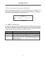
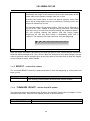
7.2.3.2 Mixed mode exposure control (command: LINE CTRL MIX)
The line period is now the time between two consecutive rising edges of the CXP-trigger signal.
The integration time is controlled internally by the command ‘LINE IT <time>’. The command
‘LINE IT <value>%’ is not available in this mode.
This mode is useful in situations, where the integration time needs to stay constant regardless
of variations in the line frequency. Each scan would then be triggered from some external
source, while the actual integration time of light would be programmed in advance as an
absolute value. The maximum integration time is always about 2 µs shorter than the line
interval. If the integration time is too long, it will be limited to the maximum, in which case it
will vary according to the line trigger input (CXP trigger) frequency. The camera monitors this
frequency. The approximate value can be read out by the command LINE RATE.
Fig. 6. Line timings in mixed control mode.
30
SW-2000M-CXP-80
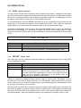
7.2.3.3 PWC mode exposure control (command: LINE CTRL PWC)
Both the line period and the integration time are controlled externally by the CXP trigger. The
time between two falling edges defines the line period. Integration starts at the rising edge and
stops at the end of the line period. Thus, effectively the exposure time is equal to the HIGH
period, while the length of one period equals the line rate.
Fig. 7. Line timings in PWC control mode.
7.2.4
LINE IT - integration time
This command is used to control the integration time (effective exposure time) for each line.
The timing can be specified either as an absolute time in microseconds, or as percentage of the
line period. The integration time given as percentage of the line interval is recalculated
automatically when the line rate changes. The integration time set in absolute units remains
constant, unless the line rate setting forces the camera to shorten it.
Command
LINE IT ?
LINE IT
LINE IT <time>
LINE IT <value>%
Description
Returns the command syntax and the available range.
Returns the present Line Integration setting.
Sets the integration time to <time> in microseconds, where <time> is a
numerical value between 2.00 – 99998.50 with 0, 1 or 2 decimal places.
Sets the integration time to <value> per cent of the maximum
integration time, where <value> is a numerical value between 0.10 % to
100.00 % (default) with 0, 1 or 2 decimal places. Not available in the
LINE CTRL MIX mode.
31
SW-2000M-CXP-80
7.2.5
GAIN – digital signal gain
The gain control can be used to scale the camera response up or down. In addition to the digital
gain control the sensor responsivity can be selected to be either Dynamic or Responsive giving a
factor of 6 in responsivity due to the difference in quantum well size. An analog gain of 2 can
be added to both options. Please refer to the SENSOR command.
It is recommended to use the SENSOR command first as far as possible and only then use the
digital gain to fine tune the response. Use of values lower than 1 may cause the maximum
output value to stay lower than the maximum value of the selected output range.
All changes in GAIN apply directly both to the signal and the dark level as well. If the dark level
needs to be maintained, it is necessary to modify the OFFSET value respectively. A coarse
estimate for the new OFFSET value can be calculated as follows and regardless of the bit depth
in use:
OFFSET ≈ 50 / GAIN – 50
Command
GAIN ?
GAIN
GAIN <value>
7.2.6
Description
Returns the command syntax.
Returns the present Gain setting.
Sets the Gain to <value>, where <value> is any number between 0.1
and 32 with up to three decimals. The default setting is 1.000
OFFSET - output offset
The value given by this command is directly added to or subtracted from all the pixel values
prior to applying the GAIN.
Command
OFFSET ?
OFFSET
OFFSET <offset>
Description
Returns the command syntax and the available range.
Returns the present Offset setting.
Changes the signal level prior to the GAIN stage.
Offset is always given as a 12-bit number. Offset changes in any 10
bit scale need to be multiplied by a factor of 4 to get the correct
value for this command. Respectively, 8 bit offsets must be
multiplied by 16. Default value is zero.
<offset> is a positive or negative integer within a range of -1023 to 1023. This equals ± 25 % of
the full scale. The offset is always entered as a 12-bit number, which means that if you have
set the camera for one of the 8-bit output modes, you should multiply the intended offset shift
by 16 to get the offset for this command.
Please keep in mind that this command changes the digital output signal level just before the
gain factor is applied. A positive number raises the output levels, while negative numbers drop
the levels. The lower limit of the adjusted level is zero. Lower output values can be used for a
Contrast Expansion, where the darkest response of an application is brought closer to zero.
32
SW-2000M-CXP-80
7.2.7
FFC – flat field correction
The function of the Flat Field Correction (FFC) is to compensate for differences in the optical
input. This can be shading due to lower transmission at the lens sides or similar optical
corrections. The Flat Field Correction should be done when the input light distribution is as
uniform as possible in order to avoid the possibility of the FFC correction adding errors to the
compensation when activated.
The procedure is then to establish a scene illumination as uniform as possible and to use the
intended optics and adjustments for the application. A uniform test target is needed. It is
recommended to calibrate the correction slightly off focal. This can be achieved either by
changing the viewing distance (recommended option) or by turning the lens a little off the best
focus.
The calibration routine first switches the correction off. The correction itself is a 2-point linear
calculation to compensate for all the pixel-specific differences both at the lowest response
levels (darkness) as well as at the bright levels, which exist when the routine is run. Two
reference lines are used. Both are an average of 32 lines. The dark reference was calibrated
already at the factory (DSNU). The bright reference is taken during the calibration. The peak
value of the bright reference is used as the target value for all the pixels.
The correction unit is loaded with the new factors and the correction is turned on. The
correction factors are saved and loaded along with the commands CS SAVE, CS SAVE2, CS LOAD
and CS LOAD2, but because there is only one common memory location available, they actually
all operate with the same data.
Command
FFC ?
FFC
FFC RUN
FFC ON
FFC OFF
Description
Returns the command syntax
Shows whether the correction is ON or OFF.
Calibrates the correction to reach the same response at all the
pixels and turns the correction on.
Activates the function.
If FFC was never run, no correction data is available and no changes
will be made to the line image.
Switches the function OFF. Default setting.
33
SW-2000M-CXP-80
7.3
Group C: Commands affecting image output format
7.3.1 CXP FORMAT
Command
CXP FORMAT ?
CXP FORMAT
CXP FORMAT MONO 8
CXP FORMAT MONO 10
CXP FORMAT MONO 12
7.3.2
Description
Returns the CXP FORMAT command syntax.
Returns the present CXP FORMAT setting.
8 bits per pixel. Default setting
10 bits per pixel.
12 bits per pixel.
READOUT – pixel readout direction
Sets the pixel readout to normal or reverse direction.
Command
READOUT ?
READOUT
READOUT NORMAL
READOUT REVERSE
Description
Returns the READOUT command syntax.
Returns the present READOUT setting.
Sets the READOUT direction to normal starting with first pixel.
Default.
Sets the READOUT direction to reverse starting with last pixel.
34
SW-2000M-CXP-80
7.3.3
ROI – regions of interest
This command can be used to select only specific sections of each line to be sent out. Up to
four regions can be defined. The selected parts of the line will be combined together to make
one, shorter line. This increases the limit of the maximum line rate, the absolute maximum still
being set by the selected MODE. There are no empty pixels or spaces in between the regions in
the output data.
Furthermore, both binning and reversed readout order can be applied after this. Please note
that all pixel number indices still and always refer to the real, physical pixel numbers of the
sensor itself. First pixel is labelled as ‘1’ and thus the last pixel is number 2048.
For simplicity and first trials it is recommended to divide the full range of pixels into 8 sections
of 256 pixels each and then select individual or groups of sections by using the respective start
and end pixel indices.
Alternatively, the selections can be optimised by following these detailed rules. The start pixel
index must always be odd and smaller than the respective end pixel index at each region and
the regions must not overlap. All indices must be within range of 1 to 2048. Minimum width of
each ROI is 128 pixels or 256 pixels, if binning is in use. Each region may have individual
widths, but they all must be divisible by 64. Additionally, GenICamTM use requires that the
index of each end pixel must be divisible by 16. Changes to selections are made by defining
the complete set again.
Examples:
Region #1
□□□□□…□□□□□□
↑
↑
X0
X1
97
352
Command
ROI ?
ROI
ROI X0-X1
ROI X0-X1, X2-X3
ROI X0-X1, X2-X3,
X4-X5
ROI X0-X1, X2-X3,
X4-X5, X6-X7
ROI ON
ROI OFF
Region #2
□□□□□□□…□□□□□□□□
↑
↑
X2
X3
401
656
Region #3
□□□…□□□
↑
↑
X4
X5
993
1248
Region #4
□□□…□□□
↑
↑
X6
X7
1409
2048
Description
Returns the syntax.
Returns the present settings.
Sets the ROI to start at pixel X0 and end at pixel X1.
Sets region #1 to start at pixel X0 and end at pixel X1
and region #2 to start at pixel X2 and end at pixel X3.
Sets region #1 to start at pixel X0 and end at pixel X1
and region #2 to start at pixel X2 and end at pixel X3
and region #3 to start at pixel X4 and end at pixel X5.
Sets region #1 to start at pixel X0 and end at pixel X1
and region #2 to start at pixel X2 and end at pixel X3
and region #3 to start at pixel X4 and end at pixel X5
and region #4 to start at pixel X6 and end at pixel X7.
Activates ROI.
If no regions are specified then all 2048 pixels will be sent out.
Returns the same regions into use, unless new regions have been
defined.
Deactivates ROI. Default setting.
35
SW-2000M-CXP-80
7.3.4
BINNING – paring of pixels
Binning mode combines adjacent pixels as pairs either to double the response by summing the
two original values or to decrease noise by taking the average of the two values. ROI operation
may be in use prior to this. Binning decreases the number of output values by a factor of two.
This increases the limit of the maximum line rate, the absolute maximum still being set by the
selected MODE.
The two output values are added together in the summing mode and the output is limited to
the maximum digital value of the original pixel values. The averaging mode sums the two
values with no maximum limit and then takes the most significant bits into use to represent the
new, combined pixel (lowest bit is removed).
The index of the first pixel of each pair must be odd.
Command
BINNING ?
BINNING
BINNING AVG
BINNING SUM
BINNING OFF
7.3.5
Description
Returns the BINNING command syntax.
Returns the present BINNING setting.
Activates BINNING in the averaging mode.
Activates BINNING in the summing mode.
Deactivates BINNING mode. Default setting.
ACQ – start and stop of acquisition
CoaXPress® links stay active after connections have been established, but actual image data is
being transferred only when the acquisition is enabled.
Command
ACQ ?
ACQ
ACQ START
ACQ STOP
Description
Returns the command syntax.
Shows the status.
Enable image transfer.
Disable image transfer.
GenICamTM compatible software uses these functions directly as needed. The acquisition should
be stopped (ACQ STOP) before any of the following telnet commands:
• ROI
• BINNING
• READOUT
• CXP FORMAT
• TEST
• LINE CTRL
• CS LOAD1, CS LOAD2
• CS FACTORY RESET
The acquisition is always disabled after power-up, restart and loading of factory settings. The
status can not be saved. The commands CS LOAD and CS LOAD2 do not change the status.
36
SW-2000M-CXP-80
7.4
7.4.1
Group D: Utilities
HELP
or
‘?’ – list of commands
7.4.2 VER - camera information
This command displays version information of various components of the camera. The
command also returns camera model number, MAC address and serial number.
Command
VER
Description
Display version information and identifiers of the camera.
7.4.3 STATUS - camera information and settings
This command includes the VER command and additionally shows all camera settings.
Command
STATUS
7.4.4
Description
Display all identifiers and user settings.
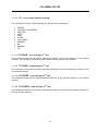
TEST - test patterns
The image data can be replaced by artificially generated, known test patterns to help
interfacing the camera, trouble shooting, and locating faults. Five patterns are available. They
all depend on the selected bit depth. Horizontal patterns ramp either up or up-down within
each line with steps that equal the selected camera output bit depth. All lines are then equal.
Vertical patterns perform the same, but in line to line direction. All values within each line are
then equal.
The last pattern, P5, is a combination of these two directions to enable tracking in both
domains with a single test pattern. It starts exactly like the horizontal pattern P1, but when
advancing to next lines it leaves the darkest pixel values out one by each line. This effectively
also shortens the length of the horizontal sequences causing the position of the horizontal
ramps to move from line to line. The last line of one sequence then finally only contains the
maximum values making it to look like one completely white line.
The lowest value is actually always the same as what the vertically changing pattern P3 would
have, if it had been started at the same time as P5. Thinking of the visual look of the pattern P3,
the correct look of this pattern (P5) can be better understood: the base level or the darkest
part of the pattern varies just like the vertically ramping P3 would vary. And while the base
level gets brighter the horizontal pattern also gets tighter as the lengths of those horizontal
ramps decrease making the respective image look like a pattern of higher frequencies.
Please note that the selection is not saved nor loaded along with the other settings. Power
cycling, rebooting and loading of factory settings will switch the test mode off.
37
SW-2000M-CXP-80
Command
TEST OFF
TEST P1
Description
No test pattern. Image data originates from the sensor (default).
Sawtooth: horizontal rising ramps from 0 to maximum. All lines are
equal. In case of 8-bit output, the line graph includes 8 such periods,
when advancing across the 2K pixels. The respective image should thus
look like this:
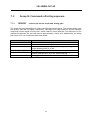
TEST P2
Triangles: horizontal ramps from 0 to maximum followed by falling
ramps from maximum to zero. All lines are equal. In case of 8-bit
output, the line graph includes 4 such periods, when advancing across
the 2K pixels. The respective image should thus look like this:
TEST P3
Vertical sawtooth: rising ramps from 0 to maximum in line to line
direction. Each line has only one value for all the pixels. In case of 8-bit
output, the ramp from black to white takes 256 lines in the respective
image:
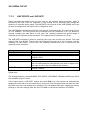
TEST P4
Vertical triangles: rising ramps from 0 to maximum followed by falling
ramps from maximum to zero in line to line direction. Each line has
only one value for all the pixels. In case of using an 8-bit output mode,
the cycle repeats itself every 512 lines. The respective image should
look like this:
38
SW-2000M-CXP-80
TEST P5
A combination of rising ramps in both directions.
Horizontally the length of the sequence varies at the same phase as the
lowest value of the pattern changes from line to line.
Vertically the lowest value of each line-specific pattern varies from
line to line as rising ramps from zero to maximum, similarly to how the
pattern P3 behaves on its own.
The resulting image is shown below (8-bit). The first line is identical to
any line of P1. Then, instead of always starting from zero, the lowest
value will rise by one per line thus also making the sequence shorter.
This will continue making the pattern look like having higher
frequencies all the way until finally a completely white line is
produced. The sequence will then start over from the beginning.
TEST
Returns information on the current status of test modes
Note: all ramps increase or decrease by one level per pixel or line, where the step follows the
selected output bit depth of 8, 10 or 12 bits. When the direction of any ramp changes, the last
value of previous ramp is repeated once as the first value of the next ramp to keep the lengths
of the sequences equal, when feasible.
7.4.5
REBOOT – restart the camera
The command REBOOT resets the camera and starts it from the beginning as if the power had
been cycled.
Command
REBOOT
7.4.6
Description
Restart the camera. Same initializations as during power-up.
Close existing Telnet sessions and start new ones as needed.
FIRMWARE UPDATE – initiate the MCU update
This command starts the loading of new firmware for the MCU. Please refer to chapter 5.12 for
detailed instructions. Also the FPGA update process is described there.
Command
FIRMWARE UPDATE
Description
Initiates the microcontroller firmware update after confirmation.
39
SW-2000M-CXP-80
8 Summary of commands
A – General settings.
Command Function Command Format
Parameter
Remarks
MODE
<file name>
fundamental settings,
reboot required
NET
NET IP <address>
NET IP AUTO
xxx.xxx.xxx.xxx
2
Camera operating
mode
Network settings
3
set IP address
4
set subnet mask
NET MASK <mask>
xxx.xxx.xxx.xxx
5
set default router
NET GATEWAY
<address>
xxx.xxx.xxx.xxx
6
reset net settings
NET FACTORY RESET
1
7
camera name
NET NAME <name>
remove the camera
8
NET NAME DELETE
name for network
NET CLOSE,
9 close session
NET QUIT or
BYE
Save capture
CS SAVE
10
settings
CS SAVE2
Load capture
CS LOAD
11
settings
CS LOAD2
Restore factory
12 settings for image
capture and save
static, DHCP off
dynamic, DHCP on
only with static
address
only with static
address
new name
affected commands:
SENSOR
LINE RATE
LINE PERIOD
LINE CTRL
LINE IT
GAIN
OFFSET
CXP FORMAT
READOUT
ROI
BINNING
FFC
CS FACTORY RESET
40
SW-2000M-CXP-80
B – Commands affecting exposure.
Command Function Command Format
Parameter
Remarks
Larger capacity,
DYNAMIC 1
lower noise.
Sensor operating
DYNAMIC 2
Smaller capacity,
1 mode and
SENSOR
RESPONSIVE 1
higher responsivity.
analog gain
RESPONSIVE 2
Followed by analog
gain of 1x or 2x.
Minimum depends
on MODE, ROI,
Line interval in µs, from
2 Line interval
LINE PERIOD <time>
binning, bit depth,
12.5 to 100 000
and link speed.
Maximum depends
Line rate
Lines per second, from 10 on MODE, ROI,
3
LINE RATE <rate>
binning, bit depth,
(note 1)
to 80,000
and link speed.
INT = internal
Recommended
MIX = external line timing, minimum line rate
4 Timing source
LINE CTRL <mode>
under external
internal integration time
PWC = Pulse Width Control control: 10 Hz.
Integration time as
Maximum depends
5
LINE IT <time>
2.00 to 99,998.60 µs
on line rate.
microseconds
Integration time as
6
LINE IT <time>%
0.10 % to 100.00 %
percentage
7 Gain
GAIN <gain>
0.100 to 32.000
no analog gain
8 Offset
OFFSET<offset>
-1023 to 1023
entered as 12 bits
Calibrate the Flat
9
FFC RUN
define and apply
Field Correction
10 activate correction FFC ON
11 deactivate
FFC OFF
Note 1.
If the status inquiry ‘LINE RATE’ returns the value 8888.0 Hz, the camera has automatically
dropped the line rate to a safe value due to a too slow CXP Link speed that has been set
after the faster line rate was already once accepted (in use or saved).
41
SW-2000M-CXP-80
C – Commands affecting image output format.
Command Function Command Format
1 CXP pixel format
2 Readout direction
Set the regions of
3
interest
4 Activate ROI
5 Deactivate ROI
6 Pixel binning
7 Start acquisition
8 Stop acquisition
CXP FORMAT
<mode>
READOUT
ROI <regions>
ROI ON
ROI OFF
BINNING <mode>
ACQ START
Parameter
MONO 8
MONO 10
MONO 12
Normal or Reverse
Pixel numbers, 1 to 4
regions.
Remarks
8 bits per pixel
10 bits per pixel
12 bits per pixel
Check the list of
requirements below.
AVG, SUM or OFF
Use before any of the
other commands of
this table.
ACQ STOP
Requirements for ROI.
For simplicity and first trials it is recommended to divide the full range of pixels into 8 sections
of 256 pixels each and then select individual or groups of sections. The following list shows the
detailed rules to optimise the regions depending on operating mode.
1.
2.
3.
4.
5.
6.
7.
8.
Pixel indices are from 1 to 2048 (also with binning).
Start index of each region must be odd.
Width of each ROI must be divisible by 64.
Width of each ROI must be at least 128 pixels.
Width of each ROI must be at least 256 pixels, if binning is in use.
Regions must not overlap.
All regions must be set at once and in ascending order of pixel indices.
GenICamTM use additionally requires that each end pixel index is divisible by 16.
42
SW-2000M-CXP-80
D – Utilities.
Command Function Command Format
1 Help
HELP or ‘?’
2
Help on any specific
command
add a ‘ ?’
3
Query of existing
setting
<command> with no
parameters
4
Camera identifiers
VER
and version numbers
Camera information
and settings
Selection of test
6
patterns
Re-booting the
7
camera
8 Firmware update
5
Parameter
Remarks
list of commands
examples:
GAIN ?
LINE RATE ?
examples:
GAIN
LINE RATE
Model, SN, MAC.
Versions: MCU, HW,
sensor, logic.
STATUS
TEST <pattern>
TEST OFF
From P1 to P5
not saved
REBOOT
close Telnet sessions
FIRMWARE UPDATE
http://10.10.10.10
43
SW-2000M-CXP-80
9 Software tools for camera communications
The camera can communicate either via GenICamTM SDK or the Ethernet (10/100) port. Both
communications can be used at the same time. The reply is sent to only the channel from
where the command was received.
CoaXPress® interface supports GenICamTM for use with compatible user software like the JAI
SDK, which can be downloaded from the JAI web site.
Ethernet port supports multiple Telnet sessions at the same time. Standard terminal programs
can be used for control at command level. Default IP address is 10.10.10.10. Telnet Port is
number 23.
JAI provides a control tool as Windows® software and a web browser access.
44
SW-2000M-CXP-80
9.1
JAI Sweep Ethernet Tool
The Sweep Ethernet Tool is a telnet terminal program with possibility to run scripts and to
display single line graphs (average of 32 lines).
Fig. 8.
Front page after initialization and the help command.
45
SW-2000M-CXP-80
Fig. 9. Line graph display with no frame grabber. Test pattern 2.
46
SW-2000M-CXP-80
9.2
Internal web server
The internal Web server can be accessed by standard web browsers at http://10.10.10.10/.
It offers some documents for download and is used while updating camera firmware.
Fig. 10.
Home page.
47
SW-2000M-CXP-80
10
External dimensions
Fig. 11.
External dimensions in mm.
48
SW-2000M-CXP-80
11
Specifications
11.1 Operating range
Parameter
Min
Typical
Max
Unit
Notes
Number of pixels
2048
-
2048
-
CMOS (custom), line scan
Pixel size
20.0
-
20.0
µm
square
Fill factor
100
-
100
%
Length of the imager
40.96
-
40.96
mm
Line scan period in the
internal mode
12.5
-
100k
µs
2
-
99,998
µs
12.5
-
100k
µs
Electronic shutter in the
internal mode
Line scan period in the
INT and PWC modes
Internal A/D conversions
12½
1x
-
12x
-
Digital gain
0.1x
-
32x
-
Lens protrusion
46.5
-
integration time
line rate: 10 Hz to 80 kHz
bit
Analog gain
Flange back distance
line rate: 10 Hz to 80 kHz
mm
only discrete values of
1x, 2x, 6x or 12x
(SENSOR command)
Nikon® F-mount
mm from flange of Nikon® F-mount
-
27
±0.1
±0.2
mm
4
-
5
W
+5
-10
-
+50
+60
°C
5
-
80
%
relative, non-condensing
Vibration
3
G
IEC 60068-2-6
Shock
25
G
IEC 60068-2-27
mm
width
height
depth
Position of optical axis
Power consumption
Temperature, operating
storage
Humidity,
operating and storage
Dimensions
(with no lens mount)
Weight
119.3
99.3
45.3
550
620
g
49
w/o lens mount
with F-mount
SW-2000M-CXP-80
Common properties
11.2
Notes
Property
Operation modes
Internal (internal line rate, internal shutter)
Mixed (external line rate, internal shutter)
Pulse Width Control, PWC (one CXP trigger for line rate and shutter)
Data interface
CoaXPress®, revision 1.0 or 1.1 (default)
Output modes
8, 10 or 12 bits
Protective glass
1.0 mm BK7 with AR coating
Communication
interface
CoaXPress® (incl. GenICamTM).
10/100 Mbps Ethernet.
Regulation
11.3
EN 61000-6-2 (2005), EMC immunity
EN 61000-6-4 (2007), EMC emissions
FCC Part 15, Subpart B
Performance per selected sensor mode
Parameter
Symbol
Responsive Dynamic
1
1
60
60
%
Quantum well size
60
360
ke-
Conversion factor
6.4
1.1
DN/ke-
240 : 1
48
580 : 1
55
dB
63
66
dB
Temporal dark noise
2.9
1.9
DN
Responsivity
480
80
DN/nJ/cm2
Linearity error
0.5
0.7
%
Quantum efficiency
Signal-to-noise ratio
Dynamic range
Notes:
•
•
•
•
•
•
QE
Unit
SNR
DR
all specifications are subject to change without notice
wavelength of light: 625 nm
DN as 12 bit
Gain: 1.0
DR = 20 lg(4095/dark noise) dB
SNR ≈ �(𝑄𝑄𝑄𝑄𝑄𝑄𝑄 𝑤𝑤𝑤𝑤 𝑠𝑠𝑠𝑠) ∶ 1
= 20 lg(SNR) dB
50
Notes
EMVA-1288
5 % to 95 % of saturation
SW-2000M-CXP-80
11.4 Spectral response
Quantum Efficiency (%)
70
60
50
40
30
20
10
0
300 350 400 450 500 550 600 650 700 750 800 850 900 950 1000 1050 1100
Wavelength (nm)
(visible light is 390 to 750 nm)
Fig. 12.
Total spectral response without lens.
51
SW-2000M-CXP-80
12 Change History
Date
March 13, 2015
Revision
1.3
Changes
First Release.
52
SW-2000M-CXP-80
User's Record
Camera type:
Sweep SW-2000M-CXP-80
Revision:
Release A, rev.1.3
Serial No.
……………
Firmware version.
MCU: 1.071
Logic: 20.017
(9 Mar 2015)
(20 Feb 2015)
Please contact your local JAI distributor for camera revision history.
User's mode settings.
User's modifications.
Company and product names mentioned in this manual are trademarks or registered trademarks of their respective owners.
JAI A-S cannot be held responsible for any technical or typographical errors and reserves the right to make changes to products and
documentation without prior notification.
Europe, Middle East & Africa
Asia Pacific
Americas
Phone +45 4457 8888
Phone +81 45 440 0154
Phone (toll-free)
+1 800 445 5444
Fax +45 4491 3252
Fax +81 45 440 0166
Visit our web site at www.jai.com
53
Phone +1 408 383 0300