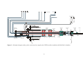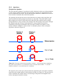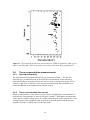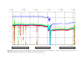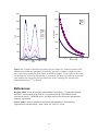
1
International
Progress Report
IPR-06-05
Äspö Hard Rock Laboratory
LTDE Long-Term Diffusion Experiment
Functionality tests with short-lived
radionuclides 2005
Henrik Widestrand
Johan Byegård
Susanne Börjesson
Anette Bergelin
Eva Wass
Geosigma AB
Svensk Kärnbränslehantering AB
January 2006
Swedish Nuclear Fuel
and Waste Management Co
Box 5864
SE-102 40 Stockholm Sweden
Tel 08-459 84 00
+46 8 459 84 00
Fax 08-661 57 19
+46 8 661 57 19
Report no.
No.
IPR-06-05
F79K
Author
Date
Henrik Widestrand
Johan Byegård
Susanne Börjesson
Anette Bergelin
Eva Wass
January 2006
Checked by
Date
Erik Gustafsson
2007-08-15
Approved
Date
Anders Sjöland
2007-09-27
Äspö Hard Rock Laboratory
LTDE Long-Term Diffusion Experiment
Functionality tests with short-lived
radionuclides 2005
Henrik Widestrand
Johan Byegård
Susanne Börjesson
Anette Bergelin
Eva Wass
Geosigma AB
January 2006
Keywords: Crystalline rock, Fractured rock, Transport properties, Diffusion, Sorption,
Diffusivity, In-situ measurements, Radionuclides, Tracers
This report concerns a study which was conducted for SKB. The conclusions
and viewpoints presented in the report are those of the author(s) and do not
necessarily coincide with those of the client.
Abstract
Within the frame of the LTDE project (in situ studying of diffusion and sorption
processes over longer time-scales) a functionality test with short-lived radionuclides has
been performed. This report describes the performance and procedures of the
functionality test together with the obtained results.
The main objectives of the test were to test injection and sampling procedures as well as
to check the functionality of individual systems such as, for example, circulation
equipment, pressure regulator, sensors, on-line measurements and alarms. It could be
concluded from the functionality test that all systems worked overall as expected. Some
minor adjustments and modifications are proposed to increase the functionality prior to
a future long term test. Also, the injection and sampling procedures concerning the
tracers functioned as planned.
Another objective of the test was to investigate if sorption, in terms of decreasing tracer
concentration in the test section, could be monitored. Both non-sorbing and sorbing
tracers were used. The following trend could be observed: Ca(II) ≤ I(-I) < Np(V) <
Cd(II) < Cs(I) < Lu(III) < Hf(IV), where no sorption of Ca(II) is observed and I(-I)
shows a weak sorption. The sorption results are discussed in relation to speciation
calculations for the different species. Surface sorption coefficients and matrix sorption
coefficients are evaluated for a batch sorption and a sorption-diffusion model
respectively. However, the sorption data presented in this report should be regarded as
indicative rather than absolute. Further, the results from the tracer experiment indicate
that sufficient mixing of the tracer solution(s) in the test section will be obtained for a
long term diffusion experiment as planned. Short-time experiments with duration of
hours to days are however unsuitable with the present borehole configuration.
The duration of the functionality test was four weeks. pH and redox potentials were
continuously monitored with an electrochemical flow cell developed for measurements
at high pressures. Furthermore, continuous pressure monitoring and additional sampling
and analysis for tracers in the first guard section, particles, microbes, radon, sorption of
tracers on tubing and groundwater chemical composition was done. The results are
shown and discussed in the report.
3
4
Sammanfattning
Inom ramen för LTDE projektet (in situ studier av diffusions- och sorptionsprocesser)
har funktionalitetsprovning med kortlivade radionuklider genomförts. Rapporten
beskriver utförande och resultat för funktionalitetstesterna.
De huvudsakliga syftena med provningen var att prova injicerings- och
provtagningsprocedurer samt att undersöka funktionaliteten för enskilda system såsom
cirkulationsutrustning, tryckregulator, olika givare, on-line mätningar och
larmfunktioner. Generellt sett fungerade alla system som förväntat. Några mindre
justeringar och förändringar föreslås för att förbättra vissa funktioner före ett framtida
långtidsförsök. Även injicering och provtagningsprocedurer fungerade som planerat.
Ett annat syfte med provningen var att undersöka om sorption, i form av minskande
spårämneskoncentration i testsektionen, kunde mätas med utrustningen. Både ickesorberande och sorberande spårämnen användes. Följande trend i sorptionsstyrka
observerades: Ca(II) ≤ I(-I) < Np(V) < Cd(II) < Cs(I) < Lu(III) < Hf(IV), där ingen
sorption av Ca(II) observerades och jod sorberade svagt. Sorptionsresultaten diskuteras
i relation till specieringsberäkningar för respektive grundämne. Ytsorptions- och
matrissorptionskoefficienter utvärderades för en enkel ytsorptionsmodell samt en
endimensionell sorptions- diffusionsmodell. Sorptionsresultaten skall dock ses som
indikativa och inte absoluta värden. Resultaten indikerar att tillräcklig omblandning av
injicerade spårämneslösningar i testsektionen fås för ett kommande långtidsförsök.
Snabba experiment med en varaktighet av timmar till dagar är dock olämpliga att
genomföra vid LTDE med nuvarande borrhålskonfigurering pga. tiden att nå fullständig
omblandning.
Funktionalitetstesten varade i 4 veckor. pH och redox-potentialer mättes kontinuerligt
med en elektrokemisk flödescell som utvecklats för mätningar vid höga tryck. Vidare så
utfördes kontinuerlig tryckmonitering och provtagning och analys av spårämnen i
guardvattnet, partiklar, mikrober, radon, sorption av spårämnen på slangar samt kemisk
analys av grundvattnet. Resultaten visas och diskuteras i rapporten.
5
6
Contents
1
Introduction
1.1 Background
1.2 Objectives
9
9
13
2
Performance
2.1 Equipment
2.1.1 Borehole KA3065A03
2.1.2 Circulation equipment in KA3065A03:1
2.1.3 On-line monitoring equipment in KA3065A03:1
2.1.4 Other equipment
2.2 Tracers
2.3 Performance of functionality test with radioactive tracers
2.3.1 Preparation of stock solutions
2.3.2 Injections
2.3.3 Sampling
2.3.4 Measurements at Baslab
2.3.5 Calibration of detectors
2.3.6 Environmental monitoring
2.4 Interpretation of tracer test
2.4.1 Simple batch surface sorption model (Ka)
2.4.2 One-dimensional sorption-diffusion model (Ka and Kd)
2.5 Other equipment tests
2.5.1 In touch surveillance functionality tests
2.5.2 Power Supply
2.5.3 Alarm system
15
15
15
17
20
22
22
24
24
25
26
26
26
27
27
27
27
28
28
28
28
3
Results and interpretation
3.1 Overview of activities
3.2 Procedures
3.2.1 Tracer injections
3.2.2 Samplings
3.2.3 Valve operations in the circulation systems
3.3 Chemical speciation of tracers
3.3.1 Groundwater chemistry measurements
3.3.2 Speciation of tracers by ion exchange resins
3.3.3 Geochemical speciation calculations
3.3.4 Radon sampling and analysis
3.3.5 20 nm filtered sampling
3.3.6 Microbe analysis
3.4 Tracer concentration measurements
3.4.1 Injected radioactivity
3.4.2 Tracer concentration-time curves
3.4.3 Sorption on tubing
3.4.4 Evaluation of surface sorption (Ka) with simple batch sorption model
3.4.5 Evaluation of surface sorption (Ka) and matrix sorption (Kd) with onedimensional diffusion model
29
29
31
31
33
34
34
34
35
36
38
39
39
40
40
40
42
42
7
43
3.5
3.6
3.7
3.8
3.9
Test section volume estimations
On-line measurements of Eh and pH
Pressure monitoring and control
Environmental monitoring
Other equipment tests
3.9.1 PLC/InTouch control and monitoring unit
3.9.2 Power Supply
3.9.3 Alarm system
3.9.4 Circulation equipment tightness test
3.10 Other observations
43
44
46
51
52
52
52
53
53
53
4
Conclusions
55
5
Future perspectives for a long term diffusion experiment
57
References
59
Appendix A: Separation and measurement of the 131Cs tracer
61
Appendix B: Detailed description of injection and sampling
67
Appendix C: One-dimensional diffusion model
(slightly modified version of SKB PIR-04-16)
71
Appendix D: Chemical analysis of KA3065A03:1 sample 2005-09-15
75
Appendix E: Chemical analysis of KA3065A03:2 sample 2005-09-15
77
8
1
Introduction
1.1
Background
Transport of radionuclides in rock fractures is presently studied within the TRUE
experimental programme. To be able to study diffusion and sorption processes over
longer time-scales a long term diffusion experiment, LTDE, has been set up at Äspö
Hard Rock Laboratory in Sweden. The original experimental plan was laid out by
Byegård et al., 1999. Since then the experimental concept has been modified to some
extent, and is currently being revised again. A recent review by Peter Vilks, AECL
Canada, gives a good overview of the developments and the present status of the project
(Vilks, 2004). The main objectives of LTDE are:
•
To investigate the magnitude and extent of diffusion in matrix rock from a
natural fracture and in fresh, un-altered rock in situ under natural rock stress
conditions and hydraulic pressure and groundwater chemical conditions.
•
To obtain data on sorption properties and processes of individual radionuclides
on natural fracture surfaces and internal surfaces in the matrix.
•
To compare laboratory derived diffusion constants and sorption coefficients for
the investigated rock fracture system with the sorption behavior observed in situ
at natural conditions, and to determine if laboratory scale sorption results are
representative also for larger scales.
The LTDE site is located in the niche at tunnel section 3065 m at a depth of
approximately -410 masl. KA3065A03 is the experimental borehole and KA3065A02
has served as exploration pilot borehole to find a suitable target structure on which to
perform the experiment, see Figure 1 for borehole locations.
9
Figure 1. Location of the LTDE experimental hole KA3065A03, and the pilot hole
KA3065A02 used to help characterize the rock in the vicinity of KA3065A03.
10
In the earlier versions of test design only the stub itself was planned to be used for the
matrix diffusion study. However, to be able to study also the diffusion in nondecompressed rock, without open fractures, a small diameter (36 mm) borehole,
approximately one metre long, has been drilled in the centre of the stub.
At the end of the experiment, the rock volume subject to diffusion is planned to be overcored, sectioned and analysed for tracer activity/concentration. The in situ
experimentation is supported by various types of mineralogical, geochemical and
petrophysical analyses.
Winberg et al. (2003) have described the geologic and geotechnical features of the rock
matrix in the vicinity of the test area in detail. Borehole imaging by BIPS (Borehole
Image Processing System) and core logging in the two boreholes were used to correlate
fractures in the two holes. The correlation was substantiated by mineralogy and
geochemical studies including stable isotopes.
Within the framework of collaboration between SKB and Ontario Power Generation’s
(OPG) Nuclear Waste Management Division supporting laboratory experiments on core
samples from the LTDE borehole KA3065A03 are in progress at Atomic Energy of
Canada Limited, AECL (Vilks et al., 2005). The experimental programme consists of
porosity measurements, diffusion cell experiments, radial diffusion experiments and
permeability measurements.
During 2004 pre-tests including hydraulic testing (flow logging, interference and
pressure build-up tests) and non radioactive tracer tests (dilution test and leakage
testing) have been performed (Wass, 2005)
Installation and installation tests of the experimental set up at LTDE have been finalised
during 2005 (according to the SKB internal document AP TD F79-01-49 v.3). A
schematic diagram of the experimental system for monitoring and sampling solutions
from the test section and the inner guard section is given in Figure 2.
This report describes a functionality test with short lived radionuclides that was
performed during September to October 2005 according to AP TD F79-05-003 (SKB
internal document). This test is a final preparation for forthcoming tests with more longlived radionuclides at the LTDE site.
11
Figure 2. Schematic diagram of experimental system for monitoring and sampling solutions from the test section and the inner guard section.
The total lengths given are measured from the borehole casing. An on-line measurement of gamma-radiation is installed in the guard section
circulation but not shown in the figure.
12
1.2
Objectives
Before the start of the long term experiment a functionality test with short lived
radionuclides was performed during September to October 2005. The results are
presented in this report. The objectives of the tests were mainly to:
•
Test the complete experimental set up with respect to functionality and safety,
including:
-
Individual functions of circulation equipment, pressure regulator, sensors,
monitoring systems, alarms, remote access to computers, backup of data etc.
-
Functions and equipment at Baslab, (the radiochemistry lab).
-
The transport of samples between Baslab and the LTDE site.
-
Radiation protection services and needs.
•
Develop and test the sampling and injection procedures in the test section and to
check that appropriate mixing of the injected tracer solutions can be obtained.
•
Investigate if sorption processes on the stub surface can be monitored with the
present experimental set-up, i.e. measurement of the decrease of tracer
concentration in the test section volume.
13
14
2
Performance
2.1
Equipment
2.1.1
Borehole KA3065A03
The experimental set-up consists of a telescoped large-diameter borehole (KA3065A03)
that intercepts a previously identified fracture. The intersected part of the fracture is
packed off using a special "packer" which seals around the developed core stub. A
solution with conservative and sorbing radioactive tracers can be injected and circulated
in the isolated section. A small diameter (36 mm) borehole, approximately one metre
long, has been drilled in the centre of the stub. 300 mm section of the small diameter
borehole is packed off for tracer circulation purposes. Further, the borehole outside the
stub is packed off with mechanical and inflatable packers to avoid effects of the acting
hydraulic gradient. A schematic diagram of the packer system used to complete the
LTDE test hole is shown in Figure 3.
15
P
Inner guardsection
P
Section
Packer regulation
Hydraulic
packers
Piston pipe
locking device
Outer pipe
Mecanical
packer
Mecanical
packer
Inner guard
section
Dummy
Core stub
Sealing
Packer
expansiongear
Guard sections
Outer seal and
packer
anchor device
Middle pipe
Centre pipe
Figure 3. Schematic diagram of the packer system used to complete the LTDE borehole installation (KA3065A03+slimhole).
16
Expander
2.1.2
Circulation equipment in KA3065A03:1
All circulation equipment such as pump, flow meter and on-line measurement of
radioactivity and electrochemical flow cell are placed in inert gas boxes. The boxes are
flushed with nitrogen in order to reduce the oxygen content in the test section
groundwater. A schematic diagram of the circulation set-up is shown in Figure 4.
Pictures of the inert gas boxes are shown in Figures 5 and 6.
All equipment is attached to 6-port valves in PEEK (Upchurch Scientific, Injection
Valve V-540) as shown in Figure 4. The flow can be directed through the external unit
attached to ports 1 and 4, or it can be bypassed to the next valve according to Figure 4.
When the valve is in the bypass position, the external units can be flushed using water
from the first guard section. The flushing is done through ports 2 and 3 in order to fill
up and pressurise the unit with groundwater prior to connecting it to the circulation.
17
Stub
“upper”
P
Stub
“lower”
36 mm
hole
A: Pump
B: Filter
C: Flow meter
Pressure
meter
G: Dose rate meter
H: Spectrometry
I: Pressure
regulator
J: Base stock
injection
K: Acidic stock
injection
D: Electrochemical cell
2
5
6
Blue-marked units in
continuous operation
during
3
2
4
5
3
6
2
1st
guard
2
4
1
5
3
10
6
G
2
4
1
5
H
3
11
6
2
4
6
1
5
3
9
1
F: Circuit to 1st guard
F
8
1
E: Sampling
4
5
D
7
1
3
4
6
4
2
4
3
3
6
5
5
C
6
1
3
4
2
4
6
3
5
3
1
2
6
4
5
B
5
6
2
3
1
6
2
1
1
2
1
A
2
1
1
5
3
12
6
2
4
I
2
4
5
1
6
6
4
5
LTDE Functionality
tests 2005
E
K
External unit
2
External unit
3
1
2
4
6
3
1
5
4
6
5
Inject
Load
Figure 4. Schematic diagram of the circulation set-up during the tests (top) and
connection diagram of the 6-port valves used for connections of equipment to the
circulation line (bottom).
18
3
13
3
15
J
2
4
5
1
3
14
6
4
5
Figure 5. Inert gas glove box for all circulation equipment excluding the pressure
regulator which is contained within a separate inert gas box.
Figure 6. Inert gas box for the pressure
regulator piston. The pressure regulators
consists of a step motor (lower picture)
which operates a piston in a PEEK
mantled cylinder (upper picture). The
motor is controlled by a separate
electronic unit. The desired difference
pressure between the test section
(KA3065A03:1) and the reference
section (first guard section
KA3065A03:2) is set in the control unit.
19
2.1.3
On-line monitoring equipment in KA3065A03:1
γ-spectrometry
The radioactivity concentration in the test section groundwater is measured on-line by
an HPGe-detector (ORTEC, relative efficiency 12%). The detector is electrically cooled
(XCooler, ORTEC). A digital multi channel analyser (DigiDart, ORTEC) is connected
to the LTDE1 computer through an USB interface. In order to avoid ground loop
disturbances, a fibre optic converter (OPTICIS optical USB extension cable M2-100) is
placed between the DigiDart and the computer to create a galvanic isolation of the two
units. The spectra were collected and analysed using the software GammaVision 5.31
(ORTEC).
The circulation tubing passes in front of the detector through a loop. The loop is
arranged so that the volume of the tubes exposed to the detector is about 5 ml. The
distance between the detector window and the tube was approximately 1, 5 cm. A
picture of the lead shield and parts of the detector is shown in Figure 7.
Figure 7. Lead shield and parts of the
HPGe-detector used for on-line radioactivity
concentration measurements.
Test section effective dose rate
The effective dose rate in a separate loop of the test section (~35 ml volume) was
monitored using a GM-probe connected to a RNI-instrument (RNI AB) in a separate
lead shield. The RNI-instrument has a data connection to the LTDE1-computer through
a RS-232 interface. The software RNICom is used to collect and display data from the
instrument. This monitoring is used to give alarm if a sudden decrease in the dose rate
of the test section loop should occur as a result of a leakage in the test section. A picture
of the lead shield and the back part of the probe is shown in Figure 8.
20
Figure 8. Lead shield and back part of the
GM-probe used for on-line dose rate monitoring.
Electrochemical flow cell
A flow-cell and a measurement system have been developed for continuous
measurements of pH and Eh at high pressures (SKB internal document, AP TD F63-0345). Figure 9 shows the flow-cell, which is made entirely in PEEK. The electrodes
situated in the flow-cell are two glass electrodes, a platinum electrode (Pt), a gold
electrode (Au) and a reference electrode (Ag, AgCl). The pH and reference electrodes
are specially designed for measurements under high pressure (Pehkonen, 2005a and b).
Calibrations are performed by circulation of calibration solutions (pH 4+quinhydrone,
pH 7+quinhydrone and pH 10). Calculation of calibration constants and recalculation of
measurement data given in mV is done manually.
Figure 9. Electrochemical flow cell used for on-line
measurements of pH and Eh.
21
2.1.4
Other equipment
Effective dose rate at fence and in container 1
The effective dose rate (in units of μSv/h) at the fence towards the tunnel and in
container 1 was monitored using RNI 10/SR-instruments (RNI AB). The data were
collected through a computer interface in the same way as described for the test section
dose rate monitoring above.
Monitoring of radioactivity in the first guard section (KA3065A03:2)
The first guard section KA3065A03:2 have a circulation equipment placed in a cabinet
outside of container 1. The radioactivity in the groundwater of the first guard section
was monitored by a 1 inch plastic scintillator probe connected to a RNI-instrument. The
probe was placed within a loop of the guard tubing in a separate lead shield. The
volume of the loop is approximately 85 ml.
Other equipment
Leak indicators are placed inside the inert gas boxes, on the floors of the containers and
in the cabinet for the guard and pilot hole circulations equipment. Difference pressure
transmitters are monitoring the pressure in the inert gas boxes. Three network cameras
are used for remote observations of container 1 and the borehole. Temperature sensors
are monitoring the temperature at a number of different positions on the site. Pressure
monitors from all borehole sections and surrounding boreholes are located in a separate
cabinet. All monitoring equipment is connected to the InTouch monitoring and control
software in the computer LTDE2 through a PLC interface in Container 2. Groups of
transmitters in InTouch are connected to the alarm system Alpha at Äspö HRL, which
in turn is connected to Clab (Central interim storage facility for spent nuclear fuel,
located near the Oskarshamn Nuclear Power Plant OKG) control room for 24h
monitoring.
2.2
Tracers
Both sorbing and non-sorbing tracers were used in the experiment. The radionuclides
that were used are summarised in Table 1. The use of the different radionuclides aims at
studying different retardation processes, e.g. sorption and diffusion. The radionuclides
have been categorised in two groups after their primary usage:
A. Non-sorbing tracers, i.e. tracers that are assumed to diffuse without retardation
due to sorption onto mineral surfaces. The inorganic anions Br- and Cl- belong to
this group.
B. Sorbing tracers, i.e. tracers that are retarded by adsorption onto mineral surfaces.
These tracers are aimed to estimate the impact of sorption on the penetration into
the rock. The proposed tracers can be divided into three different subcategories
within this group:
1.
Tracers for which the sorption is dominated by a cation exchange
mechanism
2.
Tracers for which the sorption is dominated by a surface complexation
mechanism
22
3.
Tracers that are dependent of an electrochemical reduction in order to reach
the tetravalent state (oxidation state IV) which is considered to be very
strongly sorbing. The corresponding higher oxidation state for the respective
tracer is thus considered to be weaker sorbing
Consequently, the sorbing tracers are divided into the subcategories B1, B2 and B3.
Table 1. Summary of radionuclides used in the experiment. Radionuclides given in italic
style are by-products or daughters in the production of the radionuclides aimed for
primary use in the experiment (i.e. the radionuclides in non-italic style). By-products in
radiotoxicity class B and C with a total radioactivity below 1 kBq have been omitted.
Isotope
t½
Decay Oxidation state
mode
Group
RadioInjected activity
toxicity class (kBq)
24
14.96 h
β-, γ
47
Na
Ca
4.54 d
Na(I)
B1
C
10
-
Ca(II)
B1
C
97
-
β,γ
47
Sc
3.35 d
β,γ
Sc(III)
C
9.01)
45
Ca
163 d
β-, γ
Ca(II)
B
4.32)
64
Cu
12.7 h
β-, β+
Cu(II)
B2
C
6.0
2.22 d
β-, γ
Cd(II)
B2
C
193
C
71)
115
Cd
1)
115
Cd
44.8 d
β,γ
Cd(II)
131
I
8.02 d
β-, γ
I(-I)
A
B
95
131
Cs
9.69 d
ε, γ
Cs(I)
B1
C
3.6E43)
131
Ba
11.5 d
ε, γ
Ba(II)
C
1.5
-
-
177
Lu
6.71 d
β,γ
Lu(III)
B2
C
1.7E3
181
Hf
42.39 d
β-, γ
Hf(IV)
B2
C
14
175
Hf
70.0 d
ε, γ
Hf(IV)
C
1.9
C
890
239
Np
2.355 d
β,γ
Np(V), Np(IV)
239
Pu
2.4E4 y
α
Pu (?)
A
2.4E-4
12.75 d
-
Ba(II)
B
2.5
140
Ba
-
β,γ
B3
Sum
(Radiotoxicity classed)
23 060
A:2.4E-44)
B:102
C: 3.9E4
1) The non-injected part of the stock solution had an activity below the minimum detectable
concentration at the time of measurement. Instead the non-injected part is calculated based on
the average of the radionuclides that could be measured with enough accuracy.
2) Calculated value based on neutron absorption cross section and the isotope enrichment of 44Ca in
the Ca-target.
3) No calibration source available. Total amount estimated from irradiation calculations.
4) Calculated value based on neutron absorption cross sections for 238U.
23
2.3
Performance of functionality test with radioactive tracers
One of the objectives of the functionality test with short-lived radionuclides were to test
injection and sampling procedures and the functionality of the entire system i.e.
circulation equipment, on-line measurement with HPGe-detector and environmental
monitoring. The performance of the test with radioactive short-lived tracers is described
below. Standard procedures for preparation of stock solutions and calibration of
detectors are not discussed in detail.
2.3.1
Preparation of stock solutions
Stock solutions comprising the short-lived tracers were prepared at Baslab (Clab, SKB).
Two neutron-irradiated quartz glass ampoules had been prepared with adequate amounts
of targets (salts) and sent in advance to the Institute for Energy Technology (IFE)
Kjeller, Norway. The irradiated ampoules delivered from IFE were:
1. Irradiated salts for production of 24Na, 47Ca, 64Cu, 82Br, 115Cd, 131I, 135mBa
(BaCO3 isotope enriched in 134Ba was planned to be used), 177Lu, 181Hf and
239
Np (this solution was injected first)
2. Irradiated BaCO3 of natural isotope composition for production of 131Cs (second
solution injected)
Solution 1
The contents of the ampoule was dissolved in an acidic aqueous solution and
moderately heated while stirred. After cooling, the solution was checked for its
radioactivity content, filtered and transferred to a glass bottle. Next, the solution was
pH-adjusted. To avoid sorption phenomena on glass vessels and tube walls for sorbing
tracers, the solution was prepared in a weak acid solution of approximately pH 1.5. A
small amount of a separate stock solution comprising 131I was transferred to a cation
exchange resin and eluated with distilled water. After control measurement an
appropriate amount of the 131I solution was transferred to solution 1. The solution was
then sampled to determine the final radioactivity content.
Solution 2
The preparation of the 131Cs stock solution is described in Appendix A. The stock
solution was filtered (0.45 μm) and transferred to a glass vessel. As the amount of acid
injected in solution 1 may exceed the buffer capacity of the test section site it had to be
neutralized with a base, NaOH, which was added to solution 2 (~pH 12.5). The solution
was then sampled to determine the final radioactivity content.
The two ready mixed stock solutions were then checked for external contamination,
cleared and transported as a radioactive transport to the LTDE test site according to the
routines at OKG.
24
2.3.2
Injections
Principle for injection
The first injection (solution 1) was done in acidic solution in order to avoid precipitation
of some tracers (mainly Hf and Lu) and to minimise sorption on equipment before the
tracers reached the test section. The second injection (solution 2) contained an excess of
base in order to neutralise the acidic first injection.
The principle for the injection was to inject the tracers as pulses with a plug flow and
short but sufficient time spacing between the two injections. The acidic pulse would
thus reach the test section a short time before the basic pulse and the water would be
pH-equilibrated to a large extent by the mixing in the first passage of the pulses through
the slimhole and stub sections. If precipitation or strong sorption would occur
immediately following neutralisation, this procedure would at least make it occur
mainly within the slimhole or stub sections. A schematic picture of the serial pulse
injections is shown in Figure 10.
Solution 2
(alkaline)
Solution 1
(acidic)
Before injection
0 < t < 1 min
1 < t < 11 min
Figure 10. Principle of injection procedure. At time t = 0 the tubing loop containing
the acidic stock solution 1 is switched into the circulation and at time t = 1 min the
alkaline solution 2 is switched into the circulation.
The injection valves used were placed as the last equipment at the end of the circulation
loop before the exiting outflow to the borehole sections (see Figure 4). This was done in
order to minimise the volume and to avoid mixing of the pulses with stagnant water
before entering the borehole sections.
25
Performance of injection
At the LTDE test site the stock solutions were taken through the airlock into the glove
box together with the injection loops. The specific tube volumes had been determined in
advance at Baslab. The stock solutions were transferred to the injection loops with help
of syringes. A procedure was developed whereby the only residual of the stock solutions
were left in the vessels, and could easily be returned to Baslab for sampling and
determination of the non-injected amount of radioactivity. A detailed description of the
transfer and injection procedure is given in Appendix B.
The plan for injections was to first inject solution 1 and after one minute inject solution
2, in order to avoid mixing of the solutions in the tubing. After an additional time of 10
minutes loop 2 was disconnected from the circulation and four minutes later loop 1 was
disconnected from the circulation.
2.3.3
Sampling
In addition to the on-line HPGe measurements of the circulation loop, sampling of small
volumes of water (~12 ml) was done for subsequent analysis at Baslab. A detailed
description of the sampling procedure is given in Appendix B.
2.3.4
Measurements at Baslab
HPGe
The radioactivity concentrations of the γ-emitting radionuclides were measured using an
HPGe-detector (ORTEC, relative efficiency 35%). 1 to 10 ml of the samples was
transferred to scintillation vials that were filled up with deionised water to obtain a 10
ml geometry.
Liquid scintillation
The procedures used for the measurements of 131Cs are further described in Appendix A.
2.3.5
Calibration of detectors
Prior to the start of the on-line measurements the on-line detector was calibrated with a
mixed radionuclide standard solution, Amersham QCY44. The solution was sucked
into a loop using a syringe. The calibration measurements on the HPGe detectors were
evaluated with the program package Gamma Vision 5.31, (ORTEC), which also was
used to determine the efficiency of the detectors and for measurements and evaluation
of sample spectra.
The HPGe-detector at Baslab was calibrated with a QCY44 solution. 10 ml scintillation
vial geometry was used for calibration and sample measurements.
For the liquid scintillation measurements of 131Cs no standard solution was available.
Instead, radioactivity concentration relative to the injected concentration was calculated
(C/C0). The total injected radioactivity of 131Cs was estimated based on an irradiationdecay calculation.
26
2.3.6
Environmental monitoring
The effective dose rates at the fence and in container 1 were monitored using RNIinstruments according to the description in 2.1.4. The test section (KA3065A03:1) and
the first guard section (KA3065A03:2) were monitored as described in 2.1.3 and 2.1.4
in order to detect sudden decreases of radioactivity in the test section or slow increases
of radioactivity in the guard section, respectively. Furthermore, the first guard section,
which is in primary contact with the test section, was manually sampled to check for
leakage from the test section. The pilot bore hole (KA3065A02:3) was also sampled at
the end of the experiment.
2.4
Interpretation of tracer test
2.4.1
Simple batch surface sorption model (Ka)
A simple batch sorption model is applied in which sorption is presumed to occur only
on the easily available sorption sites on the borehole walls and the stub surface; i.e., no
diffusion into the pores of the crystalline rock is considered. Application of the surface
sorption concept, the loss of tracer in the water phase can be described as:
Caq
C0
=
1
1 + Ka A /V
(1)
where C0 is the initial tracer concentration, Caq is the tracer concentration after sorption
equilibrium has been obtained, Ka (m) is the surface sorption coefficient, A (m2) is the
geometric surface of the borehole section and the stub surface and V (m3) is the total
volume of water phase (i.e., both the water in borehole section and the water in the
circulation loop).
This model approach is experimentally best addressed by determining A/V from the
dilution of a non-sorbing tracer injected together with a sorbing tracer.
2.4.2
One-dimensional sorption-diffusion model (Ka and Kd)
For the case of loss of tracer from the aqueous phase caused by diffusion into the pores
of the rock matrix surrounding the borehole and the stub surface, a simplified model is
used where the diffusion has been approximated to occur in a one-dimensional mode
(Byegård et al., 2004). With this model, Ka (m) and Kd (m3/kg), the matrix sorption
coefficient can be evaluated if the diffusion coefficient of the rock is known or
estimated from e.g. independent measurements of the porosity. The model is further
described in Appendix C.
27
2.5
Other equipment tests
2.5.1
In touch surveillance functionality tests
The inputs and outputs to the PLC-InTouch system were tested by:
1. Test of reasonableness of input values (note that this is not a calibration).
2. Temporary adjustment of alarm levels in order to trigger alarms.
3. Control of that the desired reaction of an alarm occurs, e.g. stop of circulation
pumps in case of a signal from a leak indicator etc.
4. Control of that the alarms are displayed in the alarm list.
2.5.2
Power Supply
The functionality of the battery power supplies (UPS-units) was tested in a separate test.
The diesel driven backup generator is tested monthly by Äspö HRL staff.
2.5.3
Alarm system
The coupling of the alarms from the PLC-InTouch system to the Alpha system was
tested in combination with the test described in section 2.5.1.
28
3
Results and interpretation
3.1
Overview of activities
Selection and scooping calculations of possible radionuclides were finalised in early
July, 2005. A technical description (Widestrand and Byegård, 2005) of the experiment
was accepted by SKB in the beginning of August. Prior to the start of the experiment a
number of activities were completed:
•
purchase of radionuclides,
•
remaining installations at the test site,
•
experiment preparations,
•
functionality test of equipment,
•
development and test of sampling procedures,
•
completion of on-call duty lists and alarm instructions
•
radiation protection review by the OKG staff including marking of the test site
to controlled area.
Radionuclides were delivered to OKG and transported to Baslab by internal transport at
OKG. The irradiated ampoules were transported from Kjeller, Norway in a separate
road transport conducted by IFE-personnel.
Tracer stock solutions were prepared at Baslab and the injections were done on
September 15, 2005. Sampling and analysis was continued to October 12, after which
the functionality test was officially terminated in order to let other work in the tunnel
proceed (work that potentially could cause pressure disturbances at LTDE were on hold
during the functionality test). However, some additional tests and samplings were also
done during November. A list of the major events is presented in Table 2.
29
Table 2. Log of main events during the LTDE pre test.
Date
Time
Event
050905
The power was cut while connecting up the new power supply with
diesel aggregate backup. During the power cut the UPS:s were
checked. They kept on for 30 minutes.
The power system was restarted and some switching was made to
supply equipment from the right socket.
050908-09
The electronics of the RNI instruments checked. OK.
050913
Water sample for bacterial analyse from the test section is taken.
Calibration of HPGe on-line detector.
The part of the test section loop that goes via the on-line HPGe
detector is connected to the circulation system on KA3065A03:1.
050915
050916
21.00
Prior to injection of the tracer solutions a water sample is taken from
the guard section.
23.53
Prior to injection of the tracer solutions a water sample is taken from
the test section.
23.55
Injection of the acid tracer solution starts. Valve 15 in injection position.
23.56
Injection of the basic tracer solution starts. Valve 14 in injection
position.
00.06
Injection of basic tracer solution finished. Valve 15 in load position.
00.10
Injection of acidic tracer solution finished. Valve 14 in load position.
00.35
The first sample after injection is withdrawn from the test section
circulation loop.
01.15
The second sample after injection is withdrawn.
06.09
The third sample after injection is withdrawn
12.00
Water sample no. 1 is withdrawn from the guard section.
13.40
The fourth sample after injection is withdrawn
050920
Speciation of test section sample by ion exchange resins
050920-051006
Sampling of samples #5 to #10 in the test section
050920-051012
Sampling of samples #2 to #6 in the guard section
050922
Short power cut to LTDE due to diesel generator test. Alarms from RNI
and level indicators due to absence of UPS-supply for these channels.
Restart of control equipment, RNI instruments, circulation pump and
computer LTDE2.
050926
Sampling from the test section through a filter.
051012
Sampling from the test section for analysis of radon and final sample
during the undisturbed test period (#11).
051108
Plastic scintillation probe failure (probe gives no pulse output). Probe
disconnected for reparation 051124.
051124-25
Additional test section sample #12, guard section sample #7 and
sampling of pilot borehole.
Additional sample of test section water from pressure cylinder to be
compared with sample #12.
Calibration performed of pH and redox electrodes in the flow cell done
in the glove box.
Sampling of tubes for radioactivity measurement and microbe analysis.
30
Besides the events listed above a continuous logging of the RNI instruments were made
as well as logging of data from the flow cell. A daily control of the LTDE test site has
also been performed, either on site or reading of files via computer connected to the
SKB HRL-net login. In this last case, the video cameras at the test site were used to
read, for example, the position of the pressure regulator and the circulation flow in the
test section.
3.2
Procedures
3.2.1
Tracer injections
Some of the radionuclides that were planned to be included in the tests according to the
technical description (Widestrand and Byegård, 2005) were not actually used in the
experiment for different reasons. 99mTc was said to require a medical permit according
to the supplier and could thus not be delivered. 64Cu decayed to a large extent (t1/2 =
12.7 h) between the time from removal from the reactor to injection, i.e. 4 days. 82Br
was not obtained in solution 1 as was planned, the reason for this is not clear. A possible
explanation is that due to the nitrate media used the bromide was vaporised and driven
off as Br2 gas in the drying stage of the preparation of the target. 135mBa was produced
in much lower quantities than originally calculated due to delivery from the supplier of
the 134Ba isotope in a non-soluble chemical form of, probably, BaSO4 instead of BaCO3.
This made the dissolution of the salt difficult already in the first preparation of the
ampoule prior to the irradiation. Thus, the ampoule contained very little or no 134/135mBa.
A small amount of the fission product 140Ba was produced from fission of U which only
to a slight extent compensated the loss of 135mBa.
The preparations of the stock solutions at Baslab, the transport by car to Äspö HRL and
the transport through the airlock into the glove box were done according to the plan.
However, the work to transfer the stock solutions from the vessels to the tubing loops
was hindered by the central position of the flow cell in the glove box. The flow cell
placement made it necessary to work with one hand only which was extremely difficult.
Therefore the box door on the right side had to be opened.
The flow cell was placed centrally in order to facilitate calibration; however it needs to
be placed in the inner right corner as was originally planned. The recommendation is to
rebuild the stand so that the flow cell can be easily disconnected from the stand and
moved from the corner placement to the central placement on occasions of calibration.
The injections were done as described in section 2.3.2. The second injection loop
contained some nitrogen gas, which caused a pressure dip at the injection. The nitrogen
gas was probably sucked in during the transfer of the solutions from the vessels by
moving the tube end over the solution surface. With a changed placement of the flow
cell as described above, better control of such operations can be achieved by easier
handling and better visibility in the glove box.
31
Mixing in the test section (KA3065A03:1)
The circulation time was approximately 30 to 40 minutes as can be seen in Figure 11
where the injected pulse is shown passing the GM-probe several times after the
injection. The monitor showed a peak after less than 1 day elapsed time, see Figure 12,
but this was not the true time needed to obtain a good mixing of the section since the
GM-monitor measures the actual gamma-emissions without time-corrections for the
decay. It can be seen below in the concentration – time curves of the tracers (section
3.4) that approximately 2 weeks circulation time was needed to obtain peak values of all
tracers (the strongly sorbing tracers peak earlier than the inert tracers due to the
concentration decrease caused by the sorption).
The reason for the slow mixing is likely the existence of poorly mixed zones within the
system such as the volume in the pressure regulating cylinder, the slimhole ends and
large parts of the stub surface where only diffusion exchange of water and tracers can
take part with the flowing water (the water enters the stub section in the middle of the
stub and leaves in a tube placed in the periphery).
The slow mixing in the test section is of minor importance for a sorption-diffusion test
that will last for several months or more. However, the use of the KA3065A03 borehole
for short term tests (hours to days) such as those described in the In situ Kd-report
(Byegård et al., 2004) is not recommended since the slow mixing complicates the
evaluation in such a case.
Effective dose rate test section
2005-09-15 23:55 - 2005-09-16 02:15
2,5E-06
2,0E-06
Sv/h
1,5E-06
1,0E-06
5,0E-07
0,0E+00
2005-09-15
23:35
2005-09-15
23:55
2005-09-16
00:15
2005-09-16
00:35
2005-09-16
00:55
2005-09-16
01:15
2005-09-16
01:35
2005-09-16
01:55
2005-09-16
02:15
Date and time
Figure 11. Initial peaks from the circulating pulses in the test section as monitored by
the GM-probe.
32
Effective doserate in test section loop
2005-09-16 kl 00 - 2005-09-29 kl 12
2,5E-06
2,0E-06
Sv/h
1,5E-06
Discontinuity due to power failure
1,0E-06
5,0E-07
0,0E+00
20
0
5-0
9-1
20
0
60
5-0
9-1
0:0
0
20
20
20
20
20
20
20
20
20
20
20
05
05
05
05
05
05
05
05
05
05
05
5-0
-09
-09
-09
-09
-09
-09
-09
-09
-09
-09
-09
9-1
-29
2
2
2
2
1
2
2
2
2
2
10
80
00
70
90
60
50
80
40
70
30
20
00
0: 0
0:0
0:0
0: 0
0:0
0:0
0: 0
0:0
0: 0
0:0
0:0
0:0
:00
0
0
0
0
0
0
0
0
0
0
0
0
20
0
Date and time
Figure 12. Effective dose rate during the first two weeks after injection.
3.2.2
Samplings
A total of 12 samplings of the test section groundwater were done according to the
procedure described in Appendix B. In addition, a sample was taken directly before the
injections as a reference groundwater without tracers. A written instruction for sampling
has been used and the sampling method worked as planned, however, the operation of
the needle valve requires some practical training in order to keep the pressure
disturbances low.
Sampling of the first guard section was done 7 times and of the pilot borehole once at
the end of the experiment. This sampling was done by opening of a sampling valve for
each circulation system in the cabinet outside container 1.
At two sampling occasions the pressure decreased below the set alarm level (28 bars),
once in the test section and once in the guard section. The pressure needed to be reestablished by the pressure regulator but the power to the pressure regulator was
disconnected by an automatic function in the PLC-InTouch system as long as the
pressure was below the alarm level. Therefore the power to the pressure regulator could
not be turned on again before the pressure was raised above the alarm level (or possible
if the alarm level would be adjusted temporarily to a level below the actual pressure).
The situation was solved both times by pressurising the system with the shortcut
available to the guard section. However, this automatic function should be redesigned so
that this situation can be avoided, since the pressure regulator is much faster to increase
the pressure than manual valve operations with the shortcut to the guard section.
33
3.2.3
Valve operations in the circulation systems
The circulation systems consist of a number of valves and attached units, and the space
in the glove box is densely packed with equipment. It has been noted during the tests
that the use of pre-planned checklists and instructions is beneficial to minimise the risk
for practical mistakes in different operations. Check lists should be revised for the start
of the long term diffusion experiment.
3.3
Chemical speciation of tracers
3.3.1
Groundwater chemistry measurements
The groundwater samples taken in the test and guard sections directly before the
injection 2005-09-15 were analysed by the SKB contracted laboratory. The complete
analysis results are presented in Appendix D and E. A sample containing radionuclide
tracers (2005-11-24) was analysed at OKG Nuclear Power Plant (Chemistry Laboratory
O2). The results are shown in Table 3. The results show an increased salinity in the test
section groundwater after injection, which partly can be explained by the Na, Ca, Cl and
SO4 content of the stock solutions. However, the charge balance is about 8% negative
for the 2005-11 sample. This sample was measured using ion chromatography and the
sample was diluted by a factor of 105, which cause an additional uncertainty in the Cl
and SO4 values. A calculation of the Na, Ca, Cl and SO4 concentration increase in the
test section after injection was done based on the contents in the stock solutions. The
calculated concentration increases in the test section groundwater from the stock
solution injections are 1200 ppm for Cl, 800 ppm for Na, 90 ppm for Ca and 90 ppm for
SO4. Thus, the concentration increase caused by the injection can only partly explain the
high concentrations of the 2005-11-24 sample.
Table 3. Major components analysis of test section sample after injection sampled 200511-24 (OKG laboratory), test and guard section samples before injection 2005-09-15 and
comparison with sampling January 2004 (SKB contracted laboratories).
2005-11
(OKG)
2005-09
(SKB)
2005-09
(SKB)
2004-01
(SKB)
Test section
after injection
Test section
before
injection
Guard section
Test section
Cl
8 700
5920
6150
7 020
ppm
SO4
900
409
940
417
ppm
Mg
50
46
45
42
ppm
K
10
11
11
12
ppm
Ca
2 170
1870
1880
2 030
ppm
Na
2 660
1900
1900
2 070
ppm
pH
7,5
-
-
7,3
34
3.3.2
Speciation of tracers by ion exchange resins
As a part of the effort obtaining speciation information concerning the tracers in the
groundwater, ion exchange studies were performed. Two ion exchangers were prepared,
one containing 1 ml strongly basic anion exchanger, Amberlite (16-50 mesh) and the
other containing 1 ml strongly acidic cation exchanger Dowex 50W x4 (sodium form).
During the sampling, first ~5ml was slowly (1 droplet per 5 seconds) passed through the
anion exchanger, i.e., taking the groundwater directly from the sampling valve to the ion
exchanger. The eluated water was collected in a scintillation vial and was later
measured for its tracer content (γ-spectrometry and 131Cs analysis according to the
procedures described in section 2.3.4). After that, the mentioned procedure was repeated
for sampling through the cation exchanger. Directly before the sampling through the ion
exchangers, a regular sampling had been performed.
The results of the ion exchange speciation is presented in Table 4 and are given as
concentration decrease of the tracers in the eluates from the anion and cation
exchangers, given in relation to the concentration in the non-processed sample..
Regarding the results for the presumed cations, the Cs(I), Ca(II) and Lu(III) interact as
would be expected from a cationic form; more or less completely sorbed in the cation
exchanger and passing through the anion exchanger. There are, however, some
indications of losses of especially Lu(III) in the anionic exchanger which possibly could
be caused by the existence of e.g., a negatively charged carbonate complex species, cf.
section 3.3.3. Nevertheless, the very different behaviour and also expected behaviour of
the presumed cations in the cation exchanger and anion exchanger, respectively, should
be regarded as a proof of none or very little existence of colloidal forms for these tracers.
The obtained result for the speciation of iodine is difficult to explain. Not more than
56% of the I(-I) is found to sorb on the anion exchanger. However, one should be aware
of that the high concentrations of Cl- (together with the pre-saturation of the anion
exchanger with Cl-) might act as an effective competitor for the sorption of I- on the
anion exchanger. If there is not very much higher selectivity for I- versus Cl- this could
be a possible explanation for that the I(-I) is not completely adsorbed by the anion
exchanger.
What is even more difficult to explain is the indication of adsorptive loss of I(-I) in the
cation exchanger (29%). This observation together with the unexpected indications of
sorption of I(-I) in the total experiment, illustrates the difficulties of using I(-I) as a nonsorptive tracer, a problem reviewed by e.g., Behrens 1982.
The Cd(II) tracer is almost completely adsorbed in the cation exchanger. Although the
chemical speciation calculation below indicates an existence of chloride complexes, it is
obvious that the binding to the cation exchanger is strong enough to compete out the
complexation or that the chloride complexes are adsorbed in the cation exchanger. The
large amount of adsorption of Cd in the anion exchanger is more difficult to explain.
One could speculate of the possibility of Cd forming surface complexes in the anion
exchanger with the chloride loaded on the anion exchanger. No solid proof for this
theory can, however, be delivered.
35
Np(V) is not to any significant amount adsorbed in the anion exchanger, which is in line
with the expected species (NpO2+) of that compound. However, it is somewhat
unexpected that not more than 55% of the Np(V) is adsorbed in the cation exchanger. A
possible explanation to this is that the competition from naturally present high
concentrations of cations in the groundwater (e.g., Na+ and Ca2+) and that the selectivity
for monovalent NpO2+ binding to the cation exchanger is not high enough to allow a full
adsorption.
No result was obtained for Hf(IV). This was because the concentration had already
decreased to very low amount and that not sufficient measuring time was available for
the γ-spectrometry measurement of the ion exchange processed samples to obtain
enough counting statistics for 181Hf.
Table 4. Speciation of tracers using ion exchange resins.
Tracer
Concentration
(M)
Sorbed in
cation
exchanger
Sorbed in
anion
exchanger
I(-I)
Carrier free
29 %
56 %
Cs(I)
1E-8 (nat.)
99 %
13 %
Ca(II)
0.05
>98 %
<1 %
Cd(II)
1E-7
94 %
71 %
Lu(III)
2E-10
>91 %
25 %
Hf(IV)
2E-7
Not speciated
Np(V)
Carrier free
(U – 2E-7)
55 %
3.3.3
2%
Geochemical speciation calculations
Cd and Np
Preliminary geochemical speciation calculations regarding Np and Cd have been
performed. The program PHREEQC (Parkhurst and Appelo, 1999) was used in the
calculations together with the database files from Yoshida and Shibata, (1999) and
Allison et al., (1990), used for Np and Cd, respectively. In the calculations the
groundwater composition from KA3065A03, dated 2004-01-21 was used.
The speciation calculations for Np aimed to see the distribution of the species as a
function of the redox potential, Eh. The preliminary results can be seen in Fig. 13,
which indicate that Np(V) is the dominant oxidation state above ~100 mV. The Np(V)
species are known to sorb very weakly (Carbol and Engqvist, 1997) and this may
explain the high 239Np concentration observed in the present LTDE functionality test.
The concentration of Np in the calculations was 1μM. This is a quite high figure, a more
realistic one should probably have been 2-3 orders of magnitude lower. In the
calculations NpO2(am) was found to be oversaturated, which could be explained by the
high concentration of Np. One calculation at +100 mV and with an Np concentration of
1*10-8 M, NpO2(am) was found to be undersaturated.
36
Distribution of Np species as a function of Eh.
GW from KA3065A03, 040121
100
Np(OH)4
NpO2+
80
NpO2Cl
NpO2SO4NpO2(CO3)-
60
%
40
20
0
-600
-400
-200
0
200
400
600
Eh, mV
Figure 13. Geochemical speciation calculations for Np with the use of PHREEQC
(Parkhurst and Appelo, 1999).
The purpose of the speciation calculations for Cd was to investigate to what extent this
tracer formed complexes with chlorine. The Cd concentration in the calculations was set
to the same as the experimental concentration, i.e. 4*10-7 M.
The preliminary results indicate that CdCl+ (60%) is the dominating species followed by
CdCl2 (24%) and Cd2+ (12%). See also Fig. 14. According to the calculations, the high
chloride concentration make chloride complexes to effectively dominate over other
complexes.
37
Distribution of Cd in GW from KA3065A03, 040121
70
60
50
40
%
30
20
10
C
dH
C
O
3+
dC
O
3(
aq
)
C
dB
r+
C
)
C
dO
H
C
l(a
q
C
dS
O
4(
aq
)
C
dC
l3
-
d2
+
C
dC
l2
C
C
dC
l+
0
Name of species
Figure 14. Geochemical speciation calculations for Cd with the use of PHREEQC
(Parkhurst and Appelo, 1999).
Lu and Hf
In addition to the above mentioned speciation calculations, preliminary speciation
calculations for Lu and Hf were performed. In these calculations the LLNL database
(LLNL, 2005) was used together with PHREEQC (Parkhurst and Appelo, 1999). The
LLNL database is accompanying the PHREEQC - Version 2.12.1 November 16, 2005
(Charlton and Parkhurst, 2002) package, available from USGS. The tracer
concentrations used in the calculations for Hf and Lu was taken from Table 4.
The results for Lu indicate the following dominating species: LuCO3+ (68 %) and
Lu3+(20 %). Further, the result indicates presence of the species Lu(CO3)2- (5 %) that, to
some extent, might explain the loss of Lu in the anion exchanger, cf. Table 4.
According to the preliminary results obtained for Hf the dominating species was
Hf(OH)5- (100 %), which might be doubtful since only three species were listed in the
database: Hf(OH)5-, Hf4+ and Hf(OH)3+). The Hf(OH)5- complex would also be expected
to be non-sorbing. However, if the sorption or surface complexation of Hf(IV) is
stronger than the formation of the aqueous Hf(OH)5- complex, sorption can still occur
since the equilibria then would be shifted towards the surface reactions.
3.3.4
Radon sampling and analysis
In order to estimate the radon concentration in the groundwater a 5 ml water sample was
taken. The sample was directly transferred from the sampling valve to a vial with 15 ml
Ultima Gold AB liquid scintillation cocktail of special purpose for alpha/beta
discrimination counting. The sample was measured at Baslab using the Wallac
instrument. The sample radon concentration at the time of sampling was 35 Bq/L, which
38
is low compared to typical values of fracture samples at Äspö (typically 200 to 1000
Bq/L, see e.g. Byegård et al., 2002). However, the surface to volume ratio in
KA3065A03:1 is much lower than in fractures, i.e. that the radon is diluted more in the
test section than in other boreholes.
The radon emanation (outflow) from the surfaces in the test section have been
calculated based on the known surface areas, volume and radon concentration. It should
be noted that this is a simplified approach; a more correct approach should probably
include matrix diffusion estimations for the migration of the produced radon. The radon
emanation is presented in Table 5 together with a comparison of other materials.
The result in the test section is relatively high compared to the other materials that were
measured in the laboratory. Compared to the laboratory measurement of fracture
specific material, the production rate in the in situ experiment is >60 times higher. The
large discrepancies can be seen as an indication that laboratory experiments for
estimating radon emanation not fully mimic realistic conditions. Since radon emanation
is a process analogous to matrix diffusion, the results of radon emanation can be useful
when evaluating the final diffusion experiment.
Table 5. Radon emanation from different materials at Äspö HRL.
Sample
Radon emanation
222
-1
-2
(Atoms Rn *s *m )
LTDE stub and slimhole surfaces:
KA3065A03:1 2005-10-12
600
Laboratory experiments with crushed materials
(SKB IPR-02-68):
Fine-grained granite (Äspö HRL)
160
Äspö diorite (Äspö HRL)
10
Mylonite Feature A TRUE-1
<11
3.3.5
20 nm filtered sampling
The 20 nm filtered sample (Whatman Anotop 20 nm) showed no clear differences in
concentrations neither relative the previous and following samples nor to the on-line
measurements (see Figure 16). Consequently, sorption to colloidal particles or microbes
in the groundwater larger than 20 nm is not indicated to occur to any major extent.
3.3.6
Microbe analysis
The water sample analysed for microbes shows an average value of 3.3E5 cells per ml.
This is 6 times lower than was measured at LTDE in 2002, but much higher than the
value obtained after equipment cleaning and flushing of the borehole in 2003 (about
1E3 cells per ml). The value is relatively high for deep groundwaters, but not unusual,
for this depth (see Figure 15 for a comparison of measurements). One of the microbe
types was large, which indicates that it was growing and lived under “good conditions”
(Pedersen, 2005)
39
Figure 15. Placement of the bacteria measurement at LTDE in September 2005 (green
square) and December 2002 (red square) in a matrix from other deep groundwaters.
3.4
Tracer concentration measurements
3.4.1
Injected radioactivity
The total amounts of injected radioactivity are presented in Table 1. The injected
radioactivity is calculated based on the difference measurements of the amount of
radioactivity that was transferred from the stock vessels to the injection loops. 95% of
solution 1 and 99% of solution 2 were transferred and injected, the remainders were
returned to Baslab in the original stock solution vessels.
3.4.2
Tracer concentration-time curves
Relative concentration versus time curves for on-line and laboratory measurements of
radioactivity concentrations are shown in Figures 16 and 17. Maximum concentrations
of the inert or weakly sorbing tracers are reached after about 2 weeks elapsed time. Poor
mixing in parts of the equipment such as in front of the stub surface and the pressure
regulator cylinder is a likely cause for the late peaks.
40
Observation of the relative concentrations at 13 days show an increase in sorption
strength in the order Ca(II) ≤ I(-I) < Np(V) < Cd(II) < Cs(I) < Lu(III) < Hf(IV). The
trend generally follows the charge of the major species of the sorbing complexes. Ca is
non-sorbing in the relatively saline water and weak sorption of iodine is observed. Week
sorption of iodine has been observed earlier at Äspö in e.g. the STT1-b test within the
TRUE-1 experiments (Widestrand et al., 2001). On the other hand, inert behaviour of
iodine was observed in the TRUE BS continuation project (Andersson et al., 2005).
It was suspected that the different behaviour of iodine was caused by sorption on
equipment materials in the TRUE-1 experiment. The high redox potential gives
Np(V)O2+ as major Np-species which is known to sorb weakly compared to the Np(IV)
which undergoes hydrolysis and sorbs strongly. Cadmium chloride species dominate the
Cd speciation which corresponds well to the intermediate sorption of Cd. Lu and Hf are
expected to be strongly hydrolysed and also show a relatively strong sorption.
Cs sorption is relatively strong which is in accordance with earlier field test
observations. 140Ba(II) data was relatively uncertain due to the low activity amount of
the tracer. An uncertainty analysis indicated that Ba(II) was non- or weakly sorbing
(less sorbing than iodine).
1,4E-03
Filtrated sample (20 nm)
1,2E-03
ICa2+
Lu(III)
Np(V)O2+
Cs+
Cd2+
Hf(IV)
C /A tot (1/ml)
1,0E-03
8,0E-04
6,0E-04
4,0E-04
2,0E-04
0,0E+00
0,0E+00
5,0E+00
1,0E+01
1,5E+01
2,0E+01
2,5E+01
3,0E+01
Elapsed time (d)
Figure 16. Relative concentration versus elapsed time curves for samples (dots) and
on-line measurements (lines) in linear scale. The radioactivity concentration is divided
by the total activity injected.
41
1,0E-02
ICa2+
Lu(III)
Np(V)O2+
Cs+
Cd2+
Hf(IV)
C /A tot (1/ml)
1,0E-03
1,0E-04
1,0E-05
Filtrated sample (20 nm)
1,0E-06
1,0E-02
1,0E-01
1,0E+00
1,0E+01
1,0E+02
Elapsed time (d)
Figure 17. Relative concentration versus elapsed time curves for samples (dots) and
on-line measurements (lines) in logarithmic scale. The radioactivity concentration is
divided by the total activity injected.
3.4.3
Sorption on tubing
Sorption of the only remaining (non-decayed) tracer Hf on tubing was measured on a
~20 cm tubing sample. A slight sorption of about 5 to 10 Bq/m was observed after 2
months, which corresponds to about 0.5 to 1 kBq for an estimated total tubing length of
100 m. The total injected amount of Hf was 14 kBq and after 2 months >99% of Hf was
sorbed. Consequently, only a minor part of the Hf, which was the most strongly sorbing
tracer used, is estimated to be sorbed on the tubing (<7% of the sorbed amount). An
indication of the sorption on the tubing can also be seen in Figure 17 where the
concentration determined in samples and on-line differs for Hf and Lu at the end of the
experiment.
3.4.4
Evaluation of surface sorption (Ka) with simple batch sorption
model
Surface sorption coefficients were evaluated as described in section 2.4.1 assuming that
all sorption occurred on the geometrical surfaces of the stub surface and the borehole
wall in the slimhole. The data are presented in Table 6 below.
42
3.4.5
Evaluation of surface sorption (Ka) and matrix sorption (Kd) with
one-dimensional diffusion model
Surface sorption coefficients and matrix sorption coefficients were evaluated as
described in section 2.4.2 and Appendix C. The pore diffusivity was calculated using
Archie’s law based on an assumption of 0.5% rock matrix porosity and using water
diffusivities for the different species. Kd was the only fitting parameter and Ka was
calculated based on Kd/Ka ratios obtained from the TRUE BS-project. The fitting of the
model was done to the concentration decrease at 28 days, i.e. only one data point was
modelled. The results are therefore only indicative and should not be regarded as
absolute values. The data are presented in Table 6.
Table 6. Preliminary sorption data from very basic evaluations of the functionality tests.
These data should be regarded as indicative and should be used with precaution before
a deeper evaluation including modelling of the whole data sets is done. Evaluation was
done after 28 days. Note that the diffusion model was fitted to the 28 day data point only,
i.e. that the whole data set was not modelled.
Tracer
Batch model
Surface sorption / Matrix diffusion
model
Ka (m)
Ka (m)
I(-I)
8E-3
Not modelled
Cs(I)
3E-1
0.2
Kd (m3/kg)
TRUE BS Continuation (batch
sorption experiments on rim zone
material, Byegård and Tullborg
2006)
-
0,27
Ka=(1-10)E-3 m
Kd=(1-10)E-3 m3/kg
(<3E-4)B)
Ca(II)
Ka=(2-3)E-5 mA)
Not modelled
Kd=(2-100)E-6 m3/kg A)
(<6E-3) B)
Ba(II)
Not modelled
Ka=(6-8)E-4 m
Kd=(2-50)E-4 m3/kg
Cd(II)
2E-2
1.3E-2
1,6E-2
-
Lu(III)
4
4.3
5
-
13
13
15
-
2E-2
1.6E-2
2E-2
-
Hf(IV)
Np(V)O2
+
A
Value is obtained from sorption experiments using the analogous tracer Sr2+
B
Estimated maximum value based on measurement uncertainty. Note that sorption
was to weak to be statistically verified for Ca and Ba.
3.5
Test section volume estimations
Calculation of the test section volume based on the measured dilution of the tracers
gives a volume of 930 to 970 ml at 80% filled pressure regulating cylinder which
corresponds to a maximum volume of 1030 ml. The geometrical calculations performed
estimates the volume to 880 to 950 ml at 80% filled cylinder and 960 to 1030 at 100%
which agrees well with the dilution measurement.
A rough calculation of the circulated volume based on the circulation time of the
injected pulses (35 to 40 minutes) and the flow rate (16 ml/min) gives a circulated
volume of 600 ml. This indicates that stagnant volumes are existing which is also
indicated by the relatively long time needed to obtain a good mixing in the system.
43
3.6
On-line measurements of Eh and pH
Measurements of pH and Eh were performed during a two months period (Figures 18
and 19). The electrodes were calibrated before and after the measurement and the
difference for the reference electrode was found to be less than 10 mV, which is an
acceptable normal drift considering the time span. At the time of the final calibration the
redox potential had decreased from the initial 500 mV to 200 mV (gold) and 100 mV
(platinum) and continued decreasing slowly. However, the first measurements after an
exchange of test section groundwater and a final calibration indicates an increasing
redox potential (not shown in figure). The relatively high redox potential at the
termination of the measurement and the indication of increasing redox potential after the
final calibration causes doubts regarding the possibility to reach low enough redox
potentials for reduction of redox sensitive tracers in the test section.
Oxidation of minerals in the test section during previous exposure to oxygen could be
one reason for the slow decrease of the redox potential. The borehole was open and
exposed to water in contact with air for a relatively long time (months to a year)
between the drilling and the borehole installations. The expected potential would be
about -150 mV or lower based on previous measurements in deep boreholes (Wacker et
al., 2004), which is far from the lowest observed potentials at 100 mV.
The pH was stabilising at 6.5 during the last weeks of the measurement. One of the
glass electrodes was found to be defect and it was excluded from the analysis. It can be
noted that the pH measurements on samples presented in Table 3 are typical for Äspö
groundwaters (7.3 and 7.5), but the flow cell measurements indicate stable pH at 6.5. It
can be questioned which is the correct measurement, or if both methods are correct?
Possibly, sampling may cause changes in the sample due to contact with air and
degassing which could affect the pH values of the samples. However, the effects are
usually not in this magnitude. Measurements in deep boreholes (down to 900 m in
depth) have shown that the difference between pH measured on-line in the borehole and
pH measured on surface is less than 0.5 units (Wacker et al., 2004). Typical pH values
obtained from measurements in deep boreholes range between 7 and 8.5.
The entire system seems to be sensitive to other activities in the glove box, which can
be observed as correlated peaks in the plots. The discontinuities in the plots are due to
calibration of the electrodes (August 25th), installation works at the test site and flushing
of the section with water from the guard section (September 6th and 7th). A possible
disturbance is static electrical fields which is often observed by adhesion of plastic bags,
papers etc onto the gloves in the box. There is a possibility that the measurement system
is affected by other power sources, for example the circulation pump. However, no
electrical disturbances from the pump motor or electrical cables were observed in a
previous workbench test.
A new position of the flow cell at the back of the box may reduce such disturbances. If
that does not help, the flow cell may need a metal shielding.
44
8
'Ph'
7.5
pH
7
6.5
Installation work
6
5.5
5
08-15
09-01
15
Start: 2005-08-12 00:25:24
10-01
month-day
Figure 18. pH measurement in section KA3065A03:1 2005-08-12 – 2005-10-12. The
period marked by the arrow was affected by installation works. The small peaks in the
period after 2005-09-15 are correlated to activities in the glove box.
800
'Au-hydrogen'
Installation work
'Pt-hydrogen'
600
Eh [m V]
400
200
0
Flushing of
test section
with guard water
-200
08-15
09-01
15
Start: 2005-08-12 00:25:24
10-01
month-day
Figure 19. Redox measurement in section KA3065A03:1 2005-08-12 – 2005-10-12.
The dips indicated by the vertical arrows were obtained after flushing of the test section
with groundwater from the first guard section. When flushing was discontinued and the
test section groundwater was circulated only, the redox potential increased again. The
Au-electrode was very sensitive to activities in the glove box as can be seen by the many
dips in the time period after injection 2005-09-15. The period marked by the horizontal
arrow was affected by installation works
45
The radionuclide solution was injected September 15th. A small decrease in pH was
observed shortly after the injection, which could be an effect of not obtaining a
complete neutralisation of the firstly injected acidic stock solution (Fig 20).
7.5
'Ph'
pH
7
6.5
6
5.5
00:30
40
50
Start: 2005-09-16 00:28:06
hour:min
Figure 20. pH measurement during the time of injection.
3.7
Pressure monitoring and control
All isolated borehole sections involved in the LTDE project are connected to the Hydro
Monitoring System (HMS) for pressure monitoring through the PLC.
In Figure 21a and 21b an overview of the pressure in some of the LTDE borehole
sections is presented. The experimental hydraulic conditions were stable according to
monitoring of pressure, apart from short pressure disturbances. Most of the
disturbances, seen particularly in the test and guard sections in KA3065A03, are due to
injection and sampling occasions in the borehole. One exception is the drawdown in the
end of October, i.e. after the official termination of the functionality test, and is seen in
all sections. This is caused by the re-instrumentation in the TRUE-1 boreholes KXTT3
and KXTT4, with the largest response (about 200 kPa) from KXTT4.
The LTDE area is surrounded by two dominating structures, NW-2 and NW-3. The
TRUE-1 borehole sections are within structure NW-2´, interpreted to intersect with
structure NW-2 at the TRUE-1 site. The test confirms the conclusion from the hydraulic
pre-tests (Wass, 2005), i.e the NW-2, NW-3 and related structures are of vital
importance for the hydraulic pressure responses in the LTDE boreholes and pumping,
drilling etc should not be performed in these structures during the forthcoming long
term experiment.
46
MC71 K065A3a1
LTDE
kPa
MC73 K065A3a2
LTDE
kPa
MC83 K065A2:3
LTDE
kPa
MC112 KA3067A2
MC96 KA3068A1
LTDE
kPa
kPa
MC92 SA3045A2
LTDE
kPa
3700
3650
3600
3550
3500
3450
3400
3350
3300
3250
3200
09-14
19
24
START :05/09/14 00:00:00
29
10-04
9
14
19
24
INTERVAL: All readings
29
11-03
8
13
18
23
month-day
STOP :05/11/25 00:00:00
Figure 21a. Pressure in some selected LTDE borehole sections during the period 2005-09-14–2005-11-25. See Figure 1 for borehole locations.
47
MC71 K065A3a1
LTDE
kPa
MC73 K065A3a2
LTDE
kPa
MC83 K065A2:3
LTDE
kPa
MC112 KA3067A2
MC96 KA3068A1
LTDE
kPa
kPa
MC92 SA3045A2
LTDE
kPa
3680
3660
3640
3620
3600
3580
3560
09-14
19
START :05/09/14 00:00:00
24
29
10-04
9
14
19
24
INTERVAL: All readings
29
11-03
8
13
18
23
month-day
STOP :05/11/25 00:00:00
Figure 21b. Pressure in some selected LTDE borehole sections during the period 2005-09-14 – 2005-11-25. Note that the y-axis scale is
magnified compared to Figure 21a. See Figure 1 for borehole locations.
48
The pressure regulator has been in stable operation without failures during the period
April to November. Prior to the start of the experiment the cylinder was filled up with
groundwater by running the piston backwards to a position of about 100 mm (maximum
500 mm) in order to allow for outtake of sampling volumes during the tests and still to
enable pressure regulation to lower pressures if needed.
More detailed plots over the pressure in the test and guard sections in borehole
KA3065A03 during injection and sampling procedures are shown in Figure 22. The first
injection (acidic injection, valve 15) was made at 23:55 and is not visible in the pressure
plot. The second injection (basic injection, valve 14) was made at 23:56 and the
following drawdowns around 00:35 and 01:15 are sampling occasions. The pressure dip
at the second injection 23:56 was caused by compression of nitrogen gas trapped in the
injection loop. Prior to the injection a groundwater sample was taken (approximately
between 23:52 to 23:55).
Short pressure responses in the first guard section (KA3065A03:2) is recorded at several
times in connection to pressure changes due to sampling- or injections in the test
section. It can be seen in Figure 22 (bottom) that the response in the guard section
appears both in the beginning and at the end of a drawdown in the test section. It is
observed as a pressure decrease following the opening of the test section and as a
pressure build-up when the pressure is restored by the piston movement. The reason for
this behaviour is likely due to responses through the rubber-cylinder sealing at the stub
or from penetrating tubing, i.e. a mechanical disturbance rather than a hydraulic. The
pressure in the test section was restored quickly by the pressure regulator after sampling
and injections as can be seen in Figure 22.
49
ÄSPÖ HRL
KA3065A03
KA3065A03:1
kPa
KA3065A03:2
kPa
3700
3600
3500
3400
3300
3200
3100
3000
23:50
55
5
00:00
10
15
20
25
30
35
40
45
50
55
INTERVAL: All readings
START :05/09/15 23:50:00
01:00
5
10
15
20
hour:min
STOP :05/09/16 01:20:00
ÄSPÖ HRL
KA3065A03
KA3065A03:1
kPa
KA3065A03:2
kPa
3680
3660
3640
3620
3600
3580
3560
3540
50:00
30
51:00
30
52:00
START :05/09/15 23:50:00
30
53:00
30
54:00
30
55:00
INTERVAL: All readings
30
56:00
30
57:00
30
58:00
30
59:00
30
00:00
min:sec
STOP :05/09/16 00:00:00
Figure 22. Pressure in test (red circles) and guard (green plus) sections in borehole
KA3065A03 during injection and sampling. The top figure shows injections and two
samplings in the interval 2005-09-15 23:50 to 2005-09-16 01:20. The bottom figure
shows the injection period 2005-09-15 23:50 to 00:00 in detail. Note that the y-scale is
from 3540 to 3680 kPa. A water sample is taken from 52:30 to 54:40, the first injection
is done at ~55:10 and the second injection at 56:10.
50
3.8
Environmental monitoring
Guard section
Samples were withdrawn from the guard section in order to detect any potential leakage
from the test section into the guard section. The samples were measured at Baslab on
the HPGe detector. From the obtained γ-spectra no evidence for leakage could be
observed for any of the tracers used. The spectra were also analyzed for MDA-values
(Minimum Detectable Activity). The MDA values divided by the total amount of
activity injected for 131I are presented in Table 7. 131I is the radionuclide that had the
lowest detection limit. The MDA values are time corrected. The volume of the guard
section is 10 L ± 1 L and the sample volumes measured with the HPGe detector was
10 ml.
Table 7. Detection limits for 131I that could be detected by sampling in the guard section
in the event of leakage from the test section into the guard section. The values are given
as the minimum fraction of leaked radioactivity in the test section that could be detected
in the guard section. This can be regarded as a maximum leakage fraction based on the
actual detection limits of the different samples.
Date of sample
Nuclide
Time corrected activity/Total injected amount
2005-09-16
I-131
<6E-04
2005-09-20
I-131
<2E-03
2005-09-26
I-131
<1E-03
2005-10-12
I-131
<3E-02
The on-line measurement of the guard loop showed a decreasing value with time during
the experiment which first was believed to be caused by an equilibration of the radon
content of the guard section. However, the probe finally stopped giving any pulse
output, so the results of the guard measurement may have been affected by a slow
degradation of the probe function.
Pilot borehole (KA3065A02:3)
The pilot borehole groundwater sample of 2005-11-24 showed no content of 131I, which
was an expected result since no tracers were found in the first guard section either and
the pilot borehole is further away with a larger dilution in case of a leakage.
Dose rate measurements at fence and in container 1
The dose rates at the fence and in container 1 were stable and slightly lower than 0.2
μSv/h during the test period. The contents of gamma-emitting radionuclides in the stock
solutions were quite low, about 3 MBq, which is why no significant increases in dose
rates were obtained during this experiment.
51
3.9
Other equipment tests
3.9.1
PLC/InTouch control and monitoring unit
The tests of the input and output channels showed that all channels except the oxygen
monitor in container 1 worked properly. A few channel cross couplings were discovered
and corrected during the test.
3.9.2
Power Supply
During a planned interrupt in the power supply to the LTDE test site for change of
power support, the UPS functions were monitored. The UPS units lasted for a minimum
of 30 minutes. This time is shorter than the system was originally designed for (~2h),
but good enough in the new situation where the diesel backup generator should result in
a power interrupt of about 10 to 20 s.
However, it was noted that some equipment is not supplied by the UPS units. The level
indicators and the RNI-instruments are supplied by DC-voltage without UPS backup.
Therefore the RNI-instruments needs to be restarted even after a short power interrupt.
Some other units also need to be restarted in the event of a power interrupt to LTDE.
The HPGe-detector also needs to be restarted since it has a non-UPS backuped power
supply. The reason for this is that the power from the UPS-units causes disturbances in
the HPGe-detection system, possibly from ground loops. The units that need to be
restarted are shown in Table 8.
The alarm will also be triggered from the level indicators and the RNI-instruments
during the start-up of the diesel aggregate. However, the alarms cause automatic
functions in the PLC/InTouch to disconnect other equipment (e.g. the pressure regulator
and the circulation pump are switched off). When power returns the alarms disappear,
but some of the switched off equipment needs to be manually restarted.
It is desired to install UPS-backed up power supply to the level indicators and the RNIinstruments prior to a long time experiment. Further, voltage monitoring after both earth
faults breakers is desirable. It may also be beneficial to install auxiliary contacts on the
fuses in the distribution boxes. Further, the automatic functions should be invented and
adjusted prior to a start of a long term experiment.
Table 8. Equipment that need to be manually restarted after a power interruption at
LTDE.
RNI-instruments
HPGe-detector
Circulation pumps (test section, guard section, pilot borehole section)
Pressure regulator
52
3.9.3
Alarm system
The alarms were coupled to the alpha system and tested with positive results 2005-0908. Furthermore, alarms have been triggered during the test period by testing of the
diesel backup generator (2005-09-22), communication loss with the LTDE2 computer
(2005-11-26) and by work (sampling etc) in the circulation system without prior
blocking of alarm groups (2005-11-24). The control room at Clab have had access to
the LTDE/TRUE-completion on-call duty list and alarm instructions supplied by the
project.
3.9.4
Circulation equipment tightness test
A continuous small drift in the position of the pressure regulating piston was observed
in the beginning of October. The drift was about 0.4 mm per day, thus indicating a
leakage of about 300 μl per day. Visual inspections of valves and fittings in the inert gas
boxes have not revealed the source of the leakage. The relatively high temperature and
dry nitrogen atmosphere leads to a fast evaporation of possible droplets. Salt depositions
have not either been observed, which could indicate the leakage position.
A test was performed to confirm that the leakage is within the circulation equipment in
container 1. The valves to the borehole were closed and a re-coupling of the pressure
transmitter was done in order to measure the pressure in the circulation equipment that
was now isolated from the borehole. The system outside of the borehole was pressurised
to 3470 kPa. 44 h later the pressure had decreased to 2890 kPa which indicated a leak in
the valves, fittings or equipment. In the next step, the pressure regulator was started and
the piston position was monitored. Again a drift of about 0.4 mm per day was observed.
Consequently, the small leak is probably within the equipment in container 1. Further
search to find the leakage should be done by repeating the pressure test for the different
parts of the equipment.
3.10
Other observations
The temperature in the experiment container (container 1) has been high, about 30 to
32° C during the test period. The temperature within the inert gas boxes were 2 to 5
degrees lower due to the electrical coolers. The container is insulated and the
mechanical ventilation is not sufficient to cool the heat generated by the equipment
inside the container. It is recommended to take measures in order to maintain a
temperature of about 20° C in the container.
53
54
4
Conclusions
The functionality test with short-lived radionuclides showed that concentration-time
curves based on sampling and on-line measurements of the radioactivity in the test
section can be produced with the present experimental set-up. The successively
decreasing concentrations with time for the sorbing tracers show that sorption processes
in the test section can be studied at the LTDE site. Only a minor sorption on tubing
could be measured for the most strongly sorbing tracer which indicates that the sorption
occurs to a major extent on the stub and slimhole rock surfaces. It is concluded that
sampling and on-line measurements complement each other and that both should be
done in future experiments.
Observation of the relative concentrations at 2 weeks experimental time show an
increase in sorption strength in the order Ca(II) ≤ I(-I) < Np(V) < Cd(II) < Cs(I) <
Lu(III) < Hf(IV) The trend generally follows the charge of the major species of the
sorbing complexes. Ca, with its strong hydration shell, is non-sorbing in the relatively
saline water and a weak sorption of iodine species is observed. The reason for the weak
sorption of iodine is not clear. Speciation calculations for Cd, Lu, Np and Hf give a
consistent picture of the observed concentration decreases in relation to the dominating
species for the different elements. Cs was relatively strongly sorbing in accordance with
earlier field tests at Äspö.
The experimental conditions were stable according to monitoring of pressure and pH,
apart from short pressure disturbances due to sampling and injection. The pressure
regulator worked well. The NW-2, NW-3 and related structures are of vital importance
for the hydraulic pressure responses in the LTDE boreholes. Pumping, drilling etc
should not be performed in these structures during the forthcoming long term
experiment.
The redox potential was slowly decreasing during the experiment, but still positive.
Thus, low negative redox potentials have not been obtained in the test section during the
test period with nitrogen flushing of the inert gas boxes. The redox potentials in the test
section may be affected by mineral oxidations that occurred during the time that the
borehole was open prior to the borehole installations. Consequently, more circulation
time with a closed system may be needed to obtain reducing conditions.
The tracer production, injection and sampling procedures that were developed were
functional and more than 95% of the tracers in the stock solutions were injected. About
2 weeks of circulation time were needed to obtain good mixing (constant concentration)
for the inert and weakly sorbing tracers. The slow mixing is likely caused by the
existence of zones of relatively stagnant groundwater within the circulation system such
as in front of the stub surface and in the pressure regulator cylinder. The mixing
behaviour in the test section is of minor importance for a sorption-diffusion test that will
last for several months or more. However, the use of the KA3065A03 borehole for short
term tests (hours to days) is not recommended since the slow mixing complicates the
evaluation in such a case.
55
The equipment tests show that the systems generally worked as expected. Some
modifications are proposed to be done regarding automatic alarm functions and
complementary electrical control in the system. Rearrangement of the placement of the
electrochemical flow cell in the glove box is also proposed in order to improve the
practical work in the glove box and to reduce disturbances in the measurements.
Furthermore, the experiment container needs cooling in order to reduce the temperature
from 30 to 20 degrees C. No tracers were detected in the guard section which indicates
that the test section is tight towards the guard section.
56
5
Future perspectives for a long term
diffusion experiment
A summary is given below of some points that should be considered in the planning of a
long term diffusion experiment regarding experimental and technical conditions at the
LTDE site. The actions should be planned with consideration of the duration of a future
experiment:
•
•
Experimental conditions
o
Redox potential: Since it has not yet been demonstrated that very low redox
potentials may be reached at LTDE it is also unclear whether redoxsensitive tracers can be obtained in their reduced forms in a future
experiment. However, the strong interactions of +IV metals with surfaces
may affect the actual redox potential at which the reduced form is obtained.
We therefore recommend that scooping calculations addressing sorption
reactions are done for +IV elements for the present experimental conditions.
The results can then be a base for decision of tracer selection in a future
experiment at the site. We also recommend that circulation of the test
section with redox monitoring and nitrogen flushing of the inert gas boxes
are continued to allow for maximum decrease in redox potential.
o
Non-sorbing tracers: Iodine showed a weak sorption with time in the
functionality test and is therefore not a preferred tracer in a future
experiment. The selection of an inert tracer that can be analysed in the rock
material after at least a year excludes some often used inert tracers. Tritiated
water cannot be used for rock analysis due to evaporation during handling;
bromide tracers are too short-lived; color dye tracers and metal-complexes
are undesired due to risk of complexation of the other metal tracers with
high charges. Thus, 36Cl is the only reasonable choice, although it requires
chemical separation procedures since it has no γ-emission that can be
measured using γ-spectrometry.
o
Experiment time: A minimum experiment time of 2 two 3 months is
recommended with the regards to the mixing time.
Technical conditions
o
High temperature in container 1: Increased cooling of container 1 is
required in order to decrease the temperature to about 20 degrees C.
o
Electrochemical flow cell: The flow cell position should be changed for
practical reasons and in order to decrease disturbances from glove box work.
Further reduction of possible electrical/magnetic disturbances may be
considered.
57
o
Equipment maintenance: A maintenance plan should be produced for
moving parts in the system such as the circulation pump, piston o-rings in
the pressure regulator etc. Necessary maintenance should preferentially be
done before or after experiment phases.
o
PLC automatic security functions: The automatic security functions in the
PLC/InTouch should be invented and adjusted after consideration.
o
Electrical power supplies: It is recommended to install UPS backup for
level indicators, RNI-instruments and to re-establish UPS-backup for the
HPGe detector or install a separate UPS for the HPGe. It should be
considered to install voltage monitoring after earth fault breakers and
auxiliary contacts on the fuses in the distribution boxes.
58
References
Allison, J.D., Brown, D.S., and Novo-Gradac, K.J., 1990. MINTEQA2/PRODEFA2-A geochemical assessment model for environmental systems--version 3.0 user's manual:
Environmental Research Laboratory, Office of Research and Development, U.S.
Environmental Protection Agency, Athens, Georgia, 106 p.
Andersson, P., Byegård, J., Nordqvist, R. and Wass, E., 2005. TRUE Block Scale
continuation project. BS2B tracer tests with sorbing tracers. Swedish Nuclear Fuel and
Waste Management Company, SKB IPR-05-01.
Behrens. H. New insights into the chemical behaviour of radioiodine in aquatic
environments, in Proc. “Environmental migration of long-lived radionuclides” IAEA,
Wien, 1982
Byegård, J., Johansson, H., Andersson, P., Hansson, K. and Winberg, A., 1999.
Test Plan for the Long-Term Diffusion Experiment. Swedish Nuclear Fuel and
Waste Management Company, SKB IPR-99-36.
Byegård J., Ramebäck, H. and Widestrand, H., 2002. TRUE-1 Continuation project.
Use of radon concentrations for estimation of fracture apertures – Part 1: Some method
developments, preliminary measurements and laboratory experiments. Swedish Nuclear
Fuel and Waste Management Company, SKB IPR-02-68.
Byegård, J., Nordqvist, R. and Widestrand, H., 2004. Investigation of the possibility
of using single-well in situ-sorption measurements of retention parameters in the site
investigations. Swedish Nuclear Fuel and Waste Management Company,
SKB PIR 04-16.
Byegård, J. and Tullborg, E.-L., 2006. TRUE BS Continuation, batch sorption
experiments on rim zone material, report in progress. Swedish Nuclear Fuel and Waste
Management Company
Carbol, P. and Engkvist, I., 1997. Compilation of radionuclide sorption coefficients
for performance assessment. Swedish Nuclear Fuel and Waste Management Company,
SKB R-97-13.
Charlton, S.R. and Parkhurst, D.L., 2002. PhreeqcI--A graphical user interface to the
geochemical model PHREEQC: U.S. Geological Survey Fact Sheet FS-031-02, 2 p.
LLNL, 2005. llnl.dat 2005-02-02, Data are from 'thermo.com.V8.R6.230' prepared by
Jim Johnson at Lawrence Livermore National Laboratory, in Geochemist's Workbench
format. Converted to Phreeqc format by Greg Anderson with help from David
Parkhurst. A few organic species have been omitted. Delta H of reaction calculated
from Delta H of formations given in thermo.com.V8.R6.230 (8 Mar 2000).
Parkhurst, D.L. and Appelo, C.A.J., 1999. User’s guide to PHREEQC (Version2) A computer program for speciation, batch-reaction, one-dimensional transport, and
inverse geochemical calculations: U.S. Geological Survey Water-Resources
Investigations Report 99-4259, 310 p.
59
Pedersen, K., 2005. Analys av förekomst av bakterier i LTDE, 2005-09-21. Microbial
Analytics Sweden AB.
Pehkonen, J., 2005a. Tryckkompenserad glaselektrod. Swedish Nuclear Fuel and
Waste Management Company, internal document SKB MD 433.YYYY-01,
(in progress).
Pehkonen, J., 2005bYYYY, Tryckkompenserad referenselektrod. Swedish Nuclear
Fuel and Waste Management Company, internal document SKB MD 433.YYYY-01,
(in progress).
Vilks, P., 2004. Review: Long Term Diffusion Experiment.. Swedish Nuclear Fuel and
Waste Management Company, internal document.
Vilks, P., Miller, N., H., 2005. Status report on 2004 supporting work for SKB’s long
term diffusion experiment. Report No: 06819-REP-01300-10098-R00. Nuclear Waste
Management, Ontario Power Generation.
Wacker P., Berg C. and Bergelin A., 2004. Oskarshamn site investigation. Complete
hydrochemical characterisation in KSH01A. Swedish Nuclear Fuel and Waste
Management Company, SKB P-04-12.
Wass, E., 2005. Long Term Diffusion Experiment (LTDE). Hydraulic conditions of the
LTDE experimental volume – results from Pre-tests 0.1 – 6. Swedish Nuclear Fuel and
Waste Management Company, SKB IPR-05-25.
Widestrand, H., Andersson, P., Byegård, J., Skarnemark, G., Skålberg, M. and
Wass, E, 2001. In situ migration experiments at Äspö Hard Rock Laboratory, Sweden:
results of radioactive tracer migration studies in a single fracture. Journal of
Radioanalytical and Nuclear Chemistry 250(3), 501-517,
Widestrand, H. and Byegård, J., 2005. Teknisk beskrivning av fältexperiment med
radioaktiva spårämnen i Äspölaboratoriet. LTDE – funktionalitetstester med kortlivade
radionuklider 2005. Swedish Nuclear Fuel and Waste Management Company, internal
document (in swedish).
Winberg, A., Hermanson, J., Tullborg, E.L. and Staub, I., 2003. Long-Term
Diffusion Experiment. Structural model of the LTDE site and detailed description of the
characteristics of the experimental volume including target structure and intact rock.
Swedish Nuclear Fuel and Waste Management Company, SKB IPR-03-51.
Yoshida, Y. and Shibata, M., 1999. Establishment of Data Base Files of
Thermodynamic Data developed by OECD/NEA. Part II − Thermodynamic data of Tc,
U, Np, Pu and Am with auxiliary species. JNC Technical Report, JNC TN8400 2004025 (2004, in Japanese). Waste Isolation Research Division, Waste Management and
Fuel Cycle Research Center, Japan Nuclear Cycle Development Institute (JNC),
Database Version : 011213c2.tdb. Reference thermodynamic data (except for Technetium): M.Yui,
et al. JNC Thermodynamic Database for Performance Assessment of High-level Radioactive Waste
Disposal System. JNC Technical Report, JNC TN 8400 99-070. For Technetium: Rard, J.A., et al., 1999,
Chemical Thermodynamics of Technetium, OECD Nuclear Energy Agency, Amsterdam North - Holland
60
APPENDIX A: Separation and measurement of
the 131Cs tracer
Introduction
The 131Cs tracer offers some promising properties for use in in-situ experiments. It has a
comparatively short half-life (9.69 days) which makes it advantageous in this type of
experiment where one wants the tracer to have decayed within some months. The tracer
can also be produced with very high specific activity which allows uses in very high
radioactive content without any particular increase of the chemical concentration. The
major disadvantage is that the tracer lacks measurable γ-radiation which makes the
tracer somewhat more difficult to detect and quantify.
Production
The 131Cs tracer used in this functionality test was produced by neutron irradiation (5
days) of 2.25g BaCO3(s) (99.999% purity, Aldrich) at IFE, Norway. Approximate
neutron flux was estimated to 1E13 n/s/cm2. The production occurs by neutron capture
of the stable isotope Ba-130 (0.106% of natural Ba) which then forms Ba-131 which
decays with a half life of 11.5 d to 131Cs. The cross section for neutron capture of Ba130 is 5.5 b.
The 131Cs tracer was separated from the batch approximately 4 days after the neutron
irradiation was finished. Based on calculation using the mentioned values, in some cases
rather uncertain, an amount of 36 MBq should thus be present at the injection time for
the in situ experiment.
Preparation
The irradiated BaCO3(s) was dissolved in 25 ml concentrated HCl. Thereafter, Na2SO4
was added to the solution to obtain a 10% excess of SO42- vs Ba2+. The formed
precipitation was allowed to undergo sedimentation, thereafter as much solution as
possible was extracted by a syringe and passed through a 20 nm filter. To investigate the
presence of any impurities in the solution, the extracted solution was measured by γspectrometry. The γ-spectrum and the corresponding activities of impurity isotopes in
the solution are given in Figure A-1 and Table A-1 respectively.
An interesting observation is that only 160 Bq of Ba-131 is measured in the stock
solution. Based on calculations of the produced amount of 52 MBq, it is estimated that
>99.9998% of the Ba is precipitated by the sulphate precipitation. This indicates a total
chemical concentration of Ba in the stock solution ~100 μg/l.
61
Table A-1. Isotopes identified by γ-spectrometry in the 131Cs stock solution.
Identified
isotope
ActivityA) Possible production reactions
(Bq)
t½ (d)
Isotopes obtained by irradiation of Ba
Ba-131
11.5
160
130
Ba(n, ) →131Ba
Cs-129
1.33
60
130
Ba(n, n) →129Ba(decay) →129Cs
Cs-132
6.47
2000
132
Ba(n,p) →132Cs
Cs-136
13.16
50
136
Ba(n,p) →136Cs
La-140
1.68
200
138
Ba(n, ) →139Ba(decay) →139La(n, )→140La
235
(and/or fission of impurities of U)
Isotopes obtained by irradiation of impurities in the BaCO3
Na-24
0.623
4000
23
Na(n, ) →24Na
K-42
0.515
100
41
K(n, ) →42K
As-76
1.1
300
75
As(n, ) → As
Br-82
1.47
200
81
Br(n, ) →82Br
I-131
8.02
Lu-177
6.71
400
176
Lu(n, ) →177Lu
Au-198
2.69
200
197
Au(n, ) →198Au
A)
76
50 fission of impurities of 235U (?)
Refers to the activity at the time for the injection, i.e., ~4 days after the end of the
irradiation
Ba-131,
216 keV
Ba-131,
124 keV
As-76, 559 keV
Au-198,
412 keV
La-140,
328 keV
Na-24, 1369 keV
Cs-132, 668 keV
(Na-24. double escape
from 2754 keV)
Br-82, 776 keV
Br-82, 1044 keV
K-42,1524 keV
Lu-177,
208 keV
Br-82, 828 keV
Lu-177,
113 keV
Cs-136, 818 keV
Br-82, 698 keV
Br-82, 698 keV
Br-82, 554 keV
Ba-131, 496 keV
La-140, 487 keV
Cs-132, 465 keV
Cs-129, 372 keV
I-131, 364 keV
La-140, 1596 keV
Br-82, 1475 keV
Br-82, 1317 keV
Figure A-1. Spectrum for the γ-spectrometry measurement of the 131Cs stock solution.
62
Sample measurement
Since the decay of 131Cs is not associated with any measurable γ-radiation, the much
less selective liquid scintillation counting technique has to be applied for the
measurement. Since a cocktail of radionuclides were used in this experiment,
interferences from other radionuclides should be expected for a simple sample
measurement using liquid scintillation technique. Therefore, a selective Cs separation is
advantageous for a correct quantification of 131Cs.
In this experiment, the following procedure for separation and measurement of 131Cs
was applied. A chemical separation procedure was used in which 1 ml sample was
mixed with 9 ml 0,01M HCl followed by an addition of 10 mg of ammonium
phosphomolybdate hydrate (Aldrich). This compound is known to be a very strong Cstrapper, cf. e.g. Byegård 2002. This mixture was thoroughly mixed and allowed to
equilibrate for 1 hour and thereafter the slurry was passed through a 20 nm syringe
filter. After that, 1 ml of 1M NaOH was passed through the filter (to dissolve the
Ammonium phosphomolybdate hydrate) and the solution was collected in a 20 ml
plastic scintillation tube. 15 ml of scintillation cocktail (Emulsifier Safe, Perkin Elmer)
were added and measurement was performed using a Wallac 1414 Guardian.
In order to estimate the efficiency of the separation procedure, a comparative
measurement was performed for an ammonium phosphomolybdate hydrate treated
sample and an equivalent sample spiked, without any treatment, into a scintillation
cocktail. The spectrum obtained from the different measurements together with the
graphs showing the decrease in counting rate versus time are presented in Figure A-2
(treated sample) and Figure A-3 (non-treated sample). As expected for the treated
sample, the decrease in counting rate can almost perfectly be explained from the
tabulated half-life of 131Cs, i.e. 9.69d. However, for the case of the non-treated sample, a
systematic deviation of the measured and projected values can be seen, which probably
can be explained by interferences of other (and more long-lived) radionuclides. It can be
observed that the deviation is most severe when including the high energy part of the
spectrum.
Comparing the count rate in the low energy part of the spectrum (i.e., channel # 1-180)
from the treated and non-treated sample, it can be estimated that the efficiency of the
separation process is >90%. Possible causes for obtaining this apparent non-quantitative
separation process are:
•
Non-quantitative adsorption of Cs on the ammonium phosphomolybdate (caused
by e.g., the presence of Cs in a colloidal phase in the groundwater sample).
•
Non-quantitative dissolution of the ammonium phosphomolybdate in the NaOH
treatment
•
Adsorption of Cs in the syringe filter after the dissolution
•
Quenching caused by the dissolved ammonium phosphomolybdate giving a
decreased counting rate.
Based on the observed background counting rate, an estimation of the detection limit
(Currie 1968) to 50 Bq per liter can be done by application of this method. However, a
quantitative extraction of Cs from a one litre solution to a syringe filter was shown by
Byegård 2002. Consequently, if one litre samples are available, the detection limit
should be possible to decrease to ~50 mBq per litre.
63
30000
10000
25000
8000
20000
0.0
32.5
27.8
32.5
37.1
41.8
6000
Count rate (cpm)
counts
12000
15000
4000
10000
2000
5000
0
1-180
180-320
1-1024
0
0
100
200
300
400
0
Chn#
10
20
30
40
Elapsed time (d)
Figure A-2. Liquid scintillation spectrum (left) for sample #5 (treated with ammonium
molybdenum phosphate. Results are given for a number of different times (days) after
the preparation of the liquid scintillation sample. To the right, the decrease of counting
rate versus the elapsed time is presented. The dots represents the measured value and
the line shows the projected decrease of the counting rate, based on the tabulated halflife of 131Cs (9.69 d)
64
50
30000
12000
25000
1-180
180-320
1-1024
10000
20000
0.0
18.6
27.8
32.5
37.1
41.8
6000
Count rate (cpm)
counts
8000
15000
10000
4000
5000
2000
0
0
0
0
100
200
300
10
20
30
40
Elased time (d)
400
Chn#
Figure A-3. Liquid scintillation spectrum (left) for sample #5, without treatment with
ammonium molybdenum phosphate. Results are given for a number of different times
(days) after the preparation of the liquid scintillation sample. To the right, the decrease
of counting rate versus the elapsed time is presented. The dots represents the measured
value and the line shows the projected decrease of the counting rate, based on the
tabulated half-life of 131Cs (9.69 d)
References
Byegård, 2002. Tracer Retention Understanding Experiments – Continued sampling
and tracer measurement in the TRUE-1 experiment and the TRUE Block Scale
experiment, phase C. SKB IPR-02-69, Swedish nuclear fuel and waste management
company, Stockholm.
Currie, 1968. Limits for qualitative detection and quantitative determination:
Application to radiochemistry, Anal. Chem. 40, 586-593 (1968).
65
50
66
APPENDIX B: Detailed description of injection
and sampling
1. Injection procedure
Transfer of stock solution to tubing loop
The length of each loop was adjusted to, in addition to the stock solution, hold
approximately 6-7 ml guard water. The purpose of having guard water in the beginning
and in the end of each loop was to minimize the loss of tracer solution at the transfer of
the stock solution from the glass vessel to the tubing loop.
The two loops were joined to injection valve 14 and 15, respectively, at ports 1 and 4,
see Fig. 4 and B-1. The injection valves 14 and 15 were placed in series, 14 before 15.
The injection loop joined to valve 14 comprised the alkaline stock solution while the
acidic stock solution was joined to valve 15. In the following, the procedure to load the
injection loop joined to valve 15 is outlined. The same is valid for loading of the
injection loop joined to valve 14.
A syringe was joined to port 2 and a short tube was joined to port 3 of the injection
valves. The tube had a length sufficient to reach down to the bottom of the glass vessel
containing the stock solution. When the injection valve is in its “LOAD” position, ports
1 and 2 are connected as well as ports 3 and 4. This makes it possible, with the help of
the syringe, to suck an aqueous solution, guard water or stock solution, into the loop.
The tubing loop was filled in three steps as follows (see also Figure B-1):
1) As a first step the short tube was immersed in a beaker with guard water.
Approximately 3-4 ml was sucked into the syringe-injection loop-tube set-up.
2) Next, the tube was transferred to the glass vessel and immersed in the stock
solution. The vessel was tilted to ensure that almost all of the stock solution was
sucked into the tubing loop.
3) When almost all of the stock solution was sucked into the set-up, a small amount
of guard water was added to the vessel. Suction with the syringe continued until
small droplets of water could be seen in the inlet of the syringe, indicating the
syringe-injection loop-tube set-up was filled with solution. Thereafter, the shutoff valves were closed.
67
Step 2
Step 1
2
Step 3
3
1
4
6
5
Stock
solution
bottle
Guard
water
bottle
Figure B-1. Drawing of equipment set-up for controlled transfer of the stock solution
to the injection loop. The three steps of filling the loop are described in the text above.
Thus, the stock solution was now transferred to the injection loop, ready to be connected
to the circulation equipment. The only residual of the stock solutions were left in the
vessels, and could easily be returned to Baslab and be sampled and measured to
determine the non-injected amount of radioactivity
Injection
The injection was done by switching the valve to the “INJECTION” position,
connecting ports 1 and 6 as well as ports 4 and 5. The stock solution in the injection
loop was then transferred into the circulation loop as a plug flow pulse. It was desired
that a plug flow within the tubing should be obtained until the stock solutions would
reach the experimental test section, in which mixing would occur and the two solutions
would be pH-equilibrated. A photo of the equipment set-up is shown in Figure B-2.
68
Injection loop
Syringe
Syringe
Injection
valve (#15)
Injection
valve (#14)
Stock
solution 1
(acidic)
Stock
solution 2
(alkaline)
Figure B-2. Injection valves photograph with tubes to stock solution bottles, syringes
and one injection loop visible behind the left syringe.
2. Sampling procedure
A short tube was connected to the outlet of the needle valve aimed to facilitate sampling
in 20 ml plastic vials (scintillation vials).
A description of the sampling procedure is outlined below.
1. The circulation in the test section was shut down.
2. A scintillation vial was placed under the tube.
3. Valve 9 was switched into the “INJECT” position.
4. The needle valve was opened with precaution. A pressure drop less than 2-3 bar
was desirable.
5. The valve 9 was switched to “LOAD” position when approximately 12-15 ml
had been withdrawn from the test section.
Thereafter the needle valve was set to fully open allowing remaining solution to drop
into the sample. To ensure that no solution will be left in the sampling equipment after
each sampling a syringe was joined to port 2 on valve 9 and nitrogen was pressed, with
the aid of the syringe, through port 2 and 1 to flush the needle valve and the tube.
Filtered samples
In order to be able to take filtered water samples the tube was replaced by a filter. To
the filter a syringe was joined which was arranged to fit into a scintillation vial. The
same sampling procedure as outlined above was used.
69
70
APPENDIX C: One-dimensional diffusion model
(slightly modified version of SKB PIR-04-16)
A conceptual model for the transformation of a radial diffusion case into a simplified
one-dimensional case is described in Figure C-1.
Aqueous phase
Rock matrix
Figure C-1. Conceptual model for the interpretation of a radial diffusion case into a
one-dimensional diffusion case.
The general one dimensional diffusion equation is expressed by;
∂C
∂ 2C
=D 2
∂t
∂x
(1)
In the present situation the interaction can be regarded as diffusion from a stirred
solution of limited volume into a plane sheet. In order to benefit from the analytical
solution of this case given by Crank (1975), a case where diffusion from both sides of
the sheet occurs will be considered. The sheet occupies the space -l ≤ x ≤ l, while the
solution is of limited extent and occupies the spaces -l-a ≤ x ≤ -l and l ≤ x ≤ l+a. The
occupation length of the water phase (a) is set to:
a = V / A + Ka
(2)
71
where V corresponds to the total volume used in the borehole experiment (i.e., both the
volume in the borehole section and the volume of the circulation equipment) and A is
the sum of the stub surface area and borehole wall area.
The length of the sheet (l) has no influence of the rate of the loss of tracer in the water
phase as long as the contribution of tracer diffusing from one side to the other can
therefore be neglected. The length can therefore be set arbitrarily and in this particular
case l has been set in order to obtain a tracer concentration in the middle of the sheet
(x=0) that is at least 1010 times lower than the tracer concentration in surface layer of
the sheet (i.e., x=l or x=-l)
The concentration of the solute in the solution is always uniform and is initially C0,
while the sheet initially is free from solute. The following boundary conditions therefore
apply:
C=0,
αr
∂C
∂C
= ±D
∂t
∂x
–l ≤ x ≤ l,
t=0
(3)
αr
∂C
∂C
= ±D
,
∂t
∂x
x = ±l,
t>0
(4)
and
The analytical solution to this problem has been given by Crank (1975). The total
concentration within the sheet, Cx, (including both the pore water concentration and the
mass sorbed on the rock) at the distance x at a given diffusion time of t is given by the
expression:
⎧
⎛ Da q 2j t ⎞
⎛ q x ⎞⎫
2(1 + α r ) exp⎜ − 2 ⎟ cos⎜ j ⎟ ⎪
⎪
⎜
⎜ l ⎟⎪
∞
l ⎟⎠
⎪
⎝
⎝
⎠
C x = C∞ ⎨1 + ∑
⎬
2 2
cos q j ⎪
1+αr +αr q j
⎪ j =1
⎪
⎪
⎩
⎭
(5)
where C∞ is the concentration in the sheet after infinite time and the qj values are the
non-zero positive roots of:
tan q j = −α r q j
(6)
and αr is the ratio of the capacities of the rock and water phase, defined as;
αr =
a
l (ε + K d ρ )
(7)
Furthermore, the decrease of the concentration of tracer in the start cell, C1, can be
calculated according to:
⎧
⎛ − Da q 2j t ⎞ ⎫
⎟
2α r (1 + α r ) exp⎜
⎪
⎜ l 2 ⎟ ⎪⎪
C∞ m ⎪ ∞
⎝
⎠
C1 = C1( 0 ) −
⎬
⎨1 − ∑
2 2
V1 ρ ⎪ j =1
1+α r +α r q j
⎪
⎪
⎪
⎭
⎩
where C1(0) corresponds to the initial concentration in the start cell.
72
(8)
By applying mass balance, C∞ can be calculated according to:
C∞ =
C0 a
l + a (ε + K d ρ )
(9)
However, for the present functionality test, the concentration profile within the rock will
not be possible to measure. Instead, the decrease of the concentration in the water phase
(caused by diffusion and/or sorption in the rock) will be the only available experimental
parameter that can be measured. The analytical solution for calculating the total amount
of tracer in the sheet (Mt) after a given experimental time (t) is expressed as:
⎧⎪ ∞ 2α (1 + α )
⎛ − Da q 2j t ⎞⎫⎪
Mt
r
r
⎟⎬
= 1 − ⎨∑
exp⎜
2 2
2
⎜
⎟⎪
M∞
l
+
+
q
α
α
1
⎪⎩ j =1
r
r
j
⎝
⎠⎭
(10)
where M∞ corresponds to the total amount of tracer in the sheet after infinite
experimental time. Applying mass balance, M∞ can be expressed as:
M∞ =
2aC0
1+αr
(11)
where C0 is the initial concentration of tracer in the water phase. Furthermore, Mt can be
expressed as:
M t = ( M 0 − M aq(t) ) = a (C0 − Caq(t) )
(12)
where M0 is the initial amount of tracer added to the system, Maq(t) is the amount of
tracer in the water phase after an experimental time of t and Caq(t) is the corresponding
concentration of tracer in the water phase.
By inserting (11) and (12) into (10) and by rearranging, the following expression is
obtained:
Caq(t)
C0
∞
⎧⎪ 1
⎛ − Da q 2j t ⎞⎫⎪
2α r
⎜
⎟
= 1− ⎨
−∑
exp
2 2
⎜ l 2 ⎟⎬⎪
⎪⎩1 + α r j =1 1 + α r + α r q j
⎝
⎠⎭
References
Crank, J., 1975. The mathematics of diffusion, 2nd edition, Oxford Univ. press,
London.
73
(13)
74
APPENDIX D: Chemical analysis of KA3065A03:1
sample 2005-09-15
ELEMENT
Ca
Fe
K
Mg
Na
S
Si
Al
Ba
Cd
Co
Cr
Cu
Li
Mn
Mo
Ni
P
Pb
Sr
V
Zn
La
Ce
Pr
Nd
Sm
Eu
Gd
Tb
Dy
Ho
Er
Tm
Yb
Lu
Sc
Rb
Y
Zr
Sb
Cs
Hf
Tl
U
Th
Br
I
Cl
SO4
SO4-S
SAMPLE
mg/l
mg/l
mg/l
mg/l
mg/l
mg/l
mg/l
µg/l
µg/l
µg/l
µg/l
µg/l
µg/l
µg/l
µg/l
µg/l
µg/l
µg/l
µg/l
µg/l
µg/l
µg/l
µg/l
µg/l
µg/l
µg/l
µg/l
µg/l
µg/l
µg/l
µg/l
µg/l
µg/l
µg/l
µg/l
µg/l
µg/l
µg/l
µg/l
µg/l
µg/l
µg/l
µg/l
µg/l
µg/l
µg/l
µg/l
µg/l
mg/l
mg/l
mg/l
KA3065A03:1 2005-09-15 LTDE Test sect
1870
<0.004
10,9
45,9
1900
130
5,71
11,2
92,3
0,2
<0.05
0,427
2,98
1330
59,4
56,3
6,06
<40
0,682
33800
0,0671
47,5
0,566
0,131
<0.05
<0.05
<0.05
<0.05
<0.05
<0.05
<0.05
<0.05
<0.05
<0.05
<0.05
<0.05
<0.5
37,6
0,291
3,6
0,498
5,94
0,835
<0.05
0,274
<0.2
42500
115
5923
409
137
75
76
APPENDIX E: Chemical analysis of KA3065A03:2
sample 2005-09-15
ELEMENT
Ca
Fe
K
Mg
Na
S
Si
Al
Ba
Cd
Co
Cr
Cu
Li
Mn
Mo
Ni
P
Pb
Sr
V
Zn
La
Ce
Pr
Nd
Sm
Eu
Gd
Tb
Dy
Ho
Er
Tm
Yb
Lu
Sc
Rb
Y
Zr
Sb
Cs
Hf
Tl
U
Th
Br
I
Cl
SO4
SO4-S
SAMPLE
mg/l
mg/l
mg/l
mg/l
mg/l
mg/l
mg/l
µg/l
µg/l
µg/l
µg/l
µg/l
µg/l
µg/l
µg/l
µg/l
µg/l
µg/l
µg/l
µg/l
µg/l
µg/l
µg/l
µg/l
µg/l
µg/l
µg/l
µg/l
µg/l
µg/l
µg/l
µg/l
µg/l
µg/l
µg/l
µg/l
µg/l
µg/l
µg/l
µg/l
µg/l
µg/l
µg/l
µg/l
µg/l
µg/l
µg/l
µg/l
mg/l
mg/l
mg/l
KA3065A03:2 2005-09-15 LTDEGuard sect
1880
<0.004
10,9
45,4
1900
132
5,6
4,13
83,2
0,163
0,194
0,225
1,69
1340
279
69
25,7
<40
<0.3
33600
0,0573
8,75
0,0702
<0.05
<0.05
<0.05
<0.05
<0.05
<0.05
<0.05
<0.05
<0.05
<0.05
<0.05
<0.05
<0.05
<0.5
38,1
0,246
2,41
0,398
3,67
0,601
<0.05
0,278
<0.2
42700
243
6152
943
314
77
78