1
UM0756
User manual
STEVAL-ICB003V1 front panel demonstration board
based on the STLED316S and the STMPE1208S
Introduction
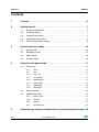
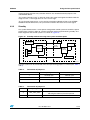
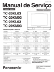
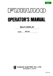
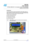
This document explains the functioning of the STEVAL-ICB003V1 demonstration board,
which represents a general purpose front panel solution utilizing an STLED316S LED driver,
STMPE1208S capacitive touch sensor and an STM8 series microcontroller (STM8S207K6).
The basic idea is to develop a generic front panel for white goods in general. Some features
such as quadrature rotary encoder interface, power management feature and a logic level
input for water level sensor have also been provided to increase versatility.
The objective of this demonstration board is to display the capabilities of STLED316S and
STMPE1208S for a sophisticated front panel to address the market segment of front panels
for DVD players, DVD recorders, set-top boxes, washing machines and many more, while
keeping system cost as low as possible. The system design focuses on 3 key areas standby management for low power consumption, general touch key as well as rotary
encoder input and a water level sensing which accepts a 38 - 43 kHz output from a water
level sensor.
All user I/O is handled by the STLED316S inputs only, with little MCU overhead. For
example, rotary encoder, buzzer and water level sensor inputs are handled by the
STLED316S only, without consuming MCU resources.
In the sections that follow, the operation of the system is explained. Once the board is
connected to the power supply, the system is ready to perform operations.
Figure 1.
STEVAL-ICB003V1 front panel demonstration board
!-V
October 2009
Doc ID 16031 Rev 1
1/28
www.st.com
Contents
UM0756
Contents
1
Features . . . . . . . . . . . . . . . . . . . . . . . . . . . . . . . . . . . . . . . . . . . . . . . . . . . 6
2
Getting started . . . . . . . . . . . . . . . . . . . . . . . . . . . . . . . . . . . . . . . . . . . . . . 7
3
4
2.1
System requirements . . . . . . . . . . . . . . . . . . . . . . . . . . . . . . . . . . . . . . . . . 7
2.2
Package content . . . . . . . . . . . . . . . . . . . . . . . . . . . . . . . . . . . . . . . . . . . . . 7
2.3
Hardware installation . . . . . . . . . . . . . . . . . . . . . . . . . . . . . . . . . . . . . . . . . 7
2.4
Powering on the system . . . . . . . . . . . . . . . . . . . . . . . . . . . . . . . . . . . . . . . 9
2.5
Default setting of the system . . . . . . . . . . . . . . . . . . . . . . . . . . . . . . . . . . . 9
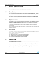
System operation modes . . . . . . . . . . . . . . . . . . . . . . . . . . . . . . . . . . . . 10
3.1
Normal mode . . . . . . . . . . . . . . . . . . . . . . . . . . . . . . . . . . . . . . . . . . . . . . 10
3.2
Brightness mode . . . . . . . . . . . . . . . . . . . . . . . . . . . . . . . . . . . . . . . . . . . 10
3.3
Demo mode . . . . . . . . . . . . . . . . . . . . . . . . . . . . . . . . . . . . . . . . . . . . . . . 10
3.4
Standby mode . . . . . . . . . . . . . . . . . . . . . . . . . . . . . . . . . . . . . . . . . . . . . 10
Using the front panel board . . . . . . . . . . . . . . . . . . . . . . . . . . . . . . . . . . 11
4.1
5
2/28
Touch keys . . . . . . . . . . . . . . . . . . . . . . . . . . . . . . . . . . . . . . . . . . . . . . . . 11
4.1.1
VOL++ . . . . . . . . . . . . . . . . . . . . . . . . . . . . . . . . . . . . . . . . . . . . . . . . . . 11
4.1.2
VOL-- . . . . . . . . . . . . . . . . . . . . . . . . . . . . . . . . . . . . . . . . . . . . . . . . . . . 11
4.1.3
CH++/UP . . . . . . . . . . . . . . . . . . . . . . . . . . . . . . . . . . . . . . . . . . . . . . . . 11
4.1.4
CH--/DOWN . . . . . . . . . . . . . . . . . . . . . . . . . . . . . . . . . . . . . . . . . . . . . . 12
4.1.5
MENU/BRGH . . . . . . . . . . . . . . . . . . . . . . . . . . . . . . . . . . . . . . . . . . . . . 12
4.1.6
Demo mode . . . . . . . . . . . . . . . . . . . . . . . . . . . . . . . . . . . . . . . . . . . . . . 13
4.1.7
WSENSOR . . . . . . . . . . . . . . . . . . . . . . . . . . . . . . . . . . . . . . . . . . . . . . 13
4.1.8
RESTORE . . . . . . . . . . . . . . . . . . . . . . . . . . . . . . . . . . . . . . . . . . . . . . . 14
4.2
Rotary encoder . . . . . . . . . . . . . . . . . . . . . . . . . . . . . . . . . . . . . . . . . . . . . 14
4.3
Additional features . . . . . . . . . . . . . . . . . . . . . . . . . . . . . . . . . . . . . . . . . . 15
4.3.1
Water sensor . . . . . . . . . . . . . . . . . . . . . . . . . . . . . . . . . . . . . . . . . . . . . 15
4.3.2
Standby . . . . . . . . . . . . . . . . . . . . . . . . . . . . . . . . . . . . . . . . . . . . . . . . . 17
4.3.3
Buzzer . . . . . . . . . . . . . . . . . . . . . . . . . . . . . . . . . . . . . . . . . . . . . . . . . . 19
4.3.4
Potentiometer . . . . . . . . . . . . . . . . . . . . . . . . . . . . . . . . . . . . . . . . . . . . . 19
Connecting an external microcontroller to the demonstration board 20
Doc ID 16031 Rev 1
UM0756
Contents
6
Schematics diagrams and bill of material . . . . . . . . . . . . . . . . . . . . . . . 21
7
Revision history . . . . . . . . . . . . . . . . . . . . . . . . . . . . . . . . . . . . . . . . . . . 27
Doc ID 16031 Rev 1
3/28
List of tables
UM0756
List of tables
Table 1.
Table 2.
Table 3.
Table 4.
Table 5.
Table 6.
Table 7.
Table 8.
4/28
Water sensor output values . . . . . . . . . . . . . . . . . . . . . . . . . . . . . . . . . . . . . . . . . . . . . . . . 15
Connection details for water sensor input to the front panel. . . . . . . . . . . . . . . . . . . . . . . . 15
Water level messages . . . . . . . . . . . . . . . . . . . . . . . . . . . . . . . . . . . . . . . . . . . . . . . . . . . . 15
Connection of jumper J1 . . . . . . . . . . . . . . . . . . . . . . . . . . . . . . . . . . . . . . . . . . . . . . . . . . . 17
Connection of jumper J3 . . . . . . . . . . . . . . . . . . . . . . . . . . . . . . . . . . . . . . . . . . . . . . . . . . . 17
Details of I2C communication with the STEVAL-ICB003V1 . . . . . . . . . . . . . . . . . . . . . . . . 18
Bill or material . . . . . . . . . . . . . . . . . . . . . . . . . . . . . . . . . . . . . . . . . . . . . . . . . . . . . . . . . . . 23
Document revision history . . . . . . . . . . . . . . . . . . . . . . . . . . . . . . . . . . . . . . . . . . . . . . . . . 27
Doc ID 16031 Rev 1
UM0756
List of figures
List of figures
Figure 1.
Figure 2.
Figure 3.
Figure 4.
Figure 5.
Figure 6.
Figure 7.
Figure 8.
Figure 9.
Figure 10.
Figure 11.
Figure 12.
Figure 13.
Figure 14.
Figure 15.
Figure 16.
Figure 17.
Figure 18.
Figure 19.
Figure 20.
STEVAL-ICB003V1 front panel demonstration board . . . . . . . . . . . . . . . . . . . . . . . . . . . . . 1
Front panel - front view . . . . . . . . . . . . . . . . . . . . . . . . . . . . . . . . . . . . . . . . . . . . . . . . . . . . . 7
Front panel - rear view . . . . . . . . . . . . . . . . . . . . . . . . . . . . . . . . . . . . . . . . . . . . . . . . . . . . . 8
Power supply connections . . . . . . . . . . . . . . . . . . . . . . . . . . . . . . . . . . . . . . . . . . . . . . . . . . 9
System stable, ready to use . . . . . . . . . . . . . . . . . . . . . . . . . . . . . . . . . . . . . . . . . . . . . . . . . 9
Volume level on the LED display . . . . . . . . . . . . . . . . . . . . . . . . . . . . . . . . . . . . . . . . . . . . 11
Channel number on the LED display . . . . . . . . . . . . . . . . . . . . . . . . . . . . . . . . . . . . . . . . . 12
Message display when the MENU/BRGH key is pressed. . . . . . . . . . . . . . . . . . . . . . . . . . 13
Demo mode message: same brightness . . . . . . . . . . . . . . . . . . . . . . . . . . . . . . . . . . . . . . 13
Demo mode message: different brightness . . . . . . . . . . . . . . . . . . . . . . . . . . . . . . . . . . . . 13
Rotary encoder . . . . . . . . . . . . . . . . . . . . . . . . . . . . . . . . . . . . . . . . . . . . . . . . . . . . . . . . . . 14
Water level message: below midpoint . . . . . . . . . . . . . . . . . . . . . . . . . . . . . . . . . . . . . . . . 16
Water level message: at midpoint. . . . . . . . . . . . . . . . . . . . . . . . . . . . . . . . . . . . . . . . . . . . 16
Water level message: above midpoint . . . . . . . . . . . . . . . . . . . . . . . . . . . . . . . . . . . . . . . . 16
Water level message: no input signal . . . . . . . . . . . . . . . . . . . . . . . . . . . . . . . . . . . . . . . . . 16
Standby mechanism using host system and front panel . . . . . . . . . . . . . . . . . . . . . . . . . . 17
Standby in progress . . . . . . . . . . . . . . . . . . . . . . . . . . . . . . . . . . . . . . . . . . . . . . . . . . . . . . 18
Standby of system after timeout . . . . . . . . . . . . . . . . . . . . . . . . . . . . . . . . . . . . . . . . . . . . . 19
Schematic of demonstration board STEVAL-ICB003V1 (1 of 2) . . . . . . . . . . . . . . . . . . . . 21
Schematic of demonstration board STEVAL-ICB003V1 (2 of 2) . . . . . . . . . . . . . . . . . . . . 22
Doc ID 16031 Rev 1
5/28
Features
1
UM0756
Features
The key features of the STEVAL-ICB003V1 demonstration board are:
6/28
●
4 seven-segment LED displays
●
8 touch keys
●
8 x 3-mm LEDs
●
1 bi-color LED for on/standby indication
●
1 interrupt assert LED
●
On-board buzzer
●
Rotary encoder for up/down functions
●
Standby management for low power operation
●
Relay for switching host power
●
Power supply connector for single 9 V supply
●
Wakeup feature from system standby
●
Embedded in-circuit programming capability through SWIM interface
●
Water level sensor input, for 38-43 kHz water sensors
Doc ID 16031 Rev 1
UM0756
Getting started
2
Getting started
2.1
System requirements
The system operates in standalone mode with a single (9 V - 15 V) DC supply. For power
supply connection, refer to Section 2.3.
2.2
Package content
The demonstration board package includes:
●
Hardware
–
●
Documentation
–
2.3
One demonstration board
User manual
Hardware installation
The demonstration board can be powered through an external power supply having a (9 V 15 V) output, typically.
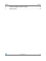
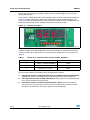
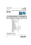
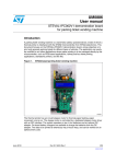
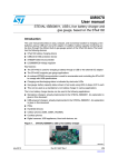
Figure 2.
Front panel - front view
3CREWTYPECONNECTOR
FORRELAYOUTPUT
3CREWTYPECONNECTOR
FORWATERSENSORINPUT
XSEGMENT
DISPLAYS
DISCRETERED,%$S
ASBRIGHTNESSLEVEL
INDICATOR
2ELAY
-#5
34-3+4
6OLTAGE
REGULATOR
,$6
,%$DRIVER
34,%$3-42
0OWER
SOCKET
"UZZER
"ICOLOR
,%$
3TANDBY
SWITCH
%NCODER
37)CONNECTOR
0OT+
%XTERNALINTERFACE
CONNECTOR
Doc ID 16031 Rev 1
)21,%$
!-V
7/28
Getting started
UM0756
The major components present on the front of the board are (see Figure 2):
●
Microcontroller - STM8S207K6T6
●
LED driver - STLED316S
●
LED display - 4 seven-segment digits
●
On-board fabricated touch keypad containing 8 touch keys
●
Relay
●
Potentiometer
●
Rotary encoder
●
5 mm pitch screw-type connector for the relay interface
●
5 mm pitch screw-type connector for water sensor input
●
LED as touch indicator
●
Standby switch
●
Bicolor LED as power-LED
●
Buzzer
●
External interface jumper
●
SWIM connector
●
Power connector
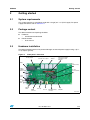
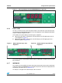
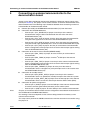
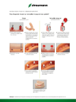
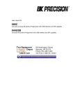
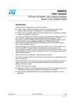
Figure 3.
Front panel - rear view
3-$,%$SFOR
TOUCHINDICATION
34OUCHCONTROLLER
34-0%3
STAGECOUNTER
(#&-42
$UAL$FLIPFLOP
-(#2-42
h"UMPONvFOR
BOARDSUPPORT
The major components present on the back of the board are (see Figure 3):
8/28
●
Touch key controller - STMPE1208S
●
14 stage counter - HCF4020
●
Dual D flip-flop - M74HC74
●
SMD LEDs as touch indicators
Doc ID 16031 Rev 1
!-V
UM0756
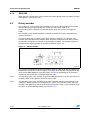
2.4
Getting started
Powering on the system
The system is easy to use. As soon as the DC power supply is connected, the system is
running. The power supply connections should be made as shown in Figure 4.
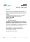
Figure 4.
Power supply connections
0OWER
CONNECTOR
0OWERCONNECTOR
!-V
At power-on a welcome message "STLED316S" is displayed, which scrolls across the LED
display from right to left.
After approximately 4-5 seconds, the last set of channel, volume and brightness values are
displayed.
Figure 5.
System stable, ready to use
6OLUMELEVEL
!-V
2.5
Default setting of the system
The system is programmed with the following default settings:
●
Channel = minimum (00)
●
Volume = minimum (00)
●
Brightness = maximum, which is level 8 (14/16)
Doc ID 16031 Rev 1
9/28
System operation modes
3
UM0756
System operation modes
The system operates in various modes depending on user actions:
3.1
Normal mode
The system operates in normal mode in normal working conditions. In this mode, the user
can increase or decrease the volume level or channel number using the touch keys or the
rotary encoder.
The user can also see the water level by touching the corresponding key. Additionally, the
user can reset the various parameters to the default values by touching the restore key.
3.2
Brightness mode
In this mode, the user can increase or decrease the brightness of the LED display using the
touch keys or the rotary encoder. The brightness level of the display is indicated by the
number of glowing discrete LEDs.
If the system is in normal mode, the user can enter brightness mode by touching the
menu/brgh key.
The system exits brightness mode after 5 seconds, or if any key other than CH++/UP or CH-/DOWN is touched.
3.3
Demo mode
In this mode, the system continues demonstrating the various types of brightness variance
options possible with the STLED316S device.
The two different modes are:
●
Constant brightness of all the digits of the STLED316S
●
Variable brightness of all the digits of the STLED316S
The system exits the demo mode if any key is touched.
3.4
Standby mode
In this mode, the front panel is in low power mode and the power of the main host system is
switched off using the on-board relay.
As the front panel is in low power mode, neither any key nor the rotary encoder operates
when the system is in the standby mode.
The system can be put into standby mode by pressing the on-board STDBY switch. The
system comes out of standby on pressing the STDBY switch again. (For details refer to
Section 4.3.2)
10/28
Doc ID 16031 Rev 1
UM0756
Using the front panel board
4
Using the front panel board
4.1
Touch keys
There are 8 different touch keys on the front panel for various operations. Whenever a key is
touched, a buzzer emits a beep and an LED blinks as an indication of the touch. The various
keys and their descriptions are provided in the sections that follow.
4.1.1
VOL++
When the system is in normal mode, the user can increase the volume by one unit by
touching the key labeled as VOL++. The volume continues to increase to its maximum value
if the user does not release the key (Figure 6).
Note:
The volume does not increase or roll back when it reaches its maximum value, which is 99.
4.1.2
VOL-When the system is in normal mode, the user can decrease the volume by one unit by
touching the key labeled as VOL--. The volume continues to decrease to its minimum value
if the user does not release the key (Figure 6).
Note:
The volume does not decrease or roll back when it reaches its minimum value, which is 00.
Figure 6.
Volume level on the LED display
6OLUMELEVEL
!-V
4.1.3
CH++/UP
When the system is in normal mode, on touching this key the channel number is increased
by one unit. The channel number continues to increase to its maximum value if the user
does not release the key.
When the system is in brightness mode, on touching this key the brightness of the display is
increased by one unit. The brightness continues to increase to its maximum value if the user
does not release the key (Figure 7).
Doc ID 16031 Rev 1
11/28
Using the front panel board
Note:
UM0756
The channel number rolls back to the minimum value (00) when it reaches its maximum
value, which is 99.
The brightness does not increase or roll back when it reaches its maximum value, which is
level 8 or 14/16.
4.1.4
CH--/DOWN
When the system is in normal mode, on touching this key the channel number is decreased
by one unit. The channel number continues to decrease to its minimum value if the user
does not release the key.
When the system is in brightness mode, on touching this key the brightness of the display is
decreased by one unit. The brightness continues to decrease to its minimum value if the
user does not release the key (Figure 7).
Note:
The channel number rolls back to the maximum value (99) when it reaches its minimum
value, which is 00.
The brightness does not decrease or roll back when it reaches its minimum value, which is
level 1 or 1/16.
Figure 7.
Channel number on the LED display
#HANNELNUMBER
!-V
4.1.5
MENU/BRGH
This key is used to put the system into brightness mode. When this key is touched the
system enters brightness mode and "8888" is displayed on the 7-segment LED display with
the current brightness level.
The brightness of the display can be increased or decreased using the CH++/UP and CH-/DOWN touch keys. The brightness can also be varied using the rotary encoder (see
Section 4.2). Discrete LEDs on the board represent the brightness level of the display
(Figure 8).
12/28
Doc ID 16031 Rev 1
UM0756
Using the front panel board
Figure 8.
Message display when the MENU/BRGH key is pressed
!-V
4.1.6
Demo mode
This key is used to put the system into demo mode. In this mode the system demonstrates
the capability of the STLED316S device to vary the brightness of the individual LED DIGIT
output to a different brightness level.
In this mode, the system displays two messages in sequence:
Figure 9.
●
When message "8881" is displayed on the LED display, the LED digits glow with the
same brightness (Figure 9).
●
When message "8882" is displayed on the LED display, the LED digits glow with a
different brightness (Figure 10).
Demo mode message: same
brightness
Figure 10. Demo mode message: different
brightness
!-V
!-V
The system remains in demo mode and messages are displayed in sequence until any other
key is touched.
4.1.7
WSENSOR
The system has the capability to measure the output of the water level sensor to determine
water level. When the WSENSOR key is touched, the present water level is displayed on the
LED display (for details refer to Section 4.3.1).
The display is changed to the default display after 5 seconds.
Doc ID 16031 Rev 1
13/28
Using the front panel board
4.1.8
UM0756
RESTORE
When this key is touched the system restores the factory default values for volume, channel
and brightness (see Section 2.5).
4.2
Rotary encoder
The system has a free-running rotary encoder on the board. This encoder can be used to
increase/decrease the volume when the system is in the normal mode, or to
increase/decrease the brightness of the LED display when the system is in brightness
mode.
The encoder can be rotated clockwise or counter-clockwise to increase or decrease the
system parameters.
The free-running rotary encoder can be given countless rotations in any direction. This
encoder gives two square wave outputs which are phase-shifted from each other, and the
type of phase shift gives an indication of the direction of rotation. The number of pulses in
the square wave signal provides the number of rotations (Figure 11).
Figure 11. Rotary encoder
!-V
In this system, the output of the rotary encoder is given to a dual D flip-flop to stabilize and
predefine the default level of the two signals. The output of the flip-flop is provided to the key
inputs of the LED316S device (see schematic in Section 6). Depending on the rotation of
the encoder the two key press interrupts follow the order.
Note:
The decoding of the rotary encoder using the STLED316S device saves the extra I/O of the
FP MCU, which would otherwise detect the sensor input.
Note:
The decoding of the rotary encoder can be done in parallel with the normal working of the
other keys, if these functions are included in the system. In the present system, the rotary
encoder is decoded along with the water level measurement, which is also connected at the
key inputs of the STLED316S device (see Section 4.3.1).
14/28
Doc ID 16031 Rev 1
UM0756
Using the front panel board
4.3
Additional features
4.3.1
Water sensor
The system has the capability to decode the output of the water level sensor. The output of
the water level sensor is a square wave signal which varies based on the level of the water.
The output signal variations are provided in table Table 1.
Table 1.
Water sensor output values
Sr. no.
Water level
Square wave frequency
1
Lower than midpoint
38 kHz
2
At midpoint
40 kHz
3
Above midpoint
43 kHz
The output of the water level sensor can be sent to connector J6 (Figure 2) on the board, the
details of which are as follows:
Table 2.
Connection details for water sensor input to the front panel
Pin. no.
Input signal
1
5V0
2
Water sensor output
3
GND
The output of the water level sensor is divided by 1024 using a digital counter (a 14-stage
counter is wired to a 10-bit counter) and is used to switch ON/OFF the transistor that is
connected between the key and segment pins of the STLED316S device. When the
transistor switches ON, the STLED316S device interprets this as a key press and interrupts
the FP MCU. The MCU reads the STLED316S interrupt and the STLED316S device again
prepares to take the other square wave input signal.
The system measures the square wave output signal every 3 seconds and processes the
result to alert the system when the water level changes from the midpoint level.
When the water level changes from the midpoint level, the buzzer in the system starts
producing an audible alarm (tic-tic-tic) until the water level again reaches the midpoint.
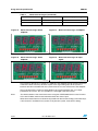
The user can see the current water level at any time by touching the WSENSOR key of the
system. As per the level of the water, the various messages are displayed on the LED
display (Figure 12 and 13, Table 3).
Table 3.
Water level messages
Sr. no.
Water level
LED display - message
1
Lower than midpoint
-LO-
2
At midpoint
----
Doc ID 16031 Rev 1
15/28
Using the front panel board
Table 3.
UM0756
Water level messages (continued)
Sr. no.
Water level
LED display - message
3
Above midpoint
-HI-
4
No input signal
|||
Figure 12. Water level message: below
midpoint
Figure 13. Water level message: at midpoint
!-V
!-V
Figure 14. Water level message: above
midpoint
Figure 15. Water level message: no input
signal
!-V
!-V
The system by design has a margin of +/- 500 Hz at the midpoint level to compensate for the
water level sensor accuracy. So if the square wave signal being input to the system is
between 39.5 kHz and 40.5 kHz, the system will show it as the water level at the midpoint.
Also, if the input to the system is below 30 kHz, the system interprets this as no input
provided to the system. This is to provide for a damaged water level sensor.
Note:
The measurement of the water level sensor using the STLED316S device saves the extra
I/O of the FP MCU, which would otherwise detect the sensor input.
Water level measurement can be done in parallel with the normal working of the other keys,
if this function is included in the system. In the present system, water level is being
16/28
Doc ID 16031 Rev 1
UM0756
Using the front panel board
measured along with the rotary encoder which is also attached at the key inputs of the
STLED316S device.
The system operates at 5 V, so the logic level of the water level signal should be within the
range of 3.5 V - 5 V for high and 0 V - 1.5 V for low logic.
To use the water level sensor, a 1 kΩ resistor should be soldered on R33 of the STEVALICB003V1 board. Without this, the system will not detect the water sensor level signal.
Standby
The system demonstrates a smart power management control system to control the power
of other host systems in order to save the maximum amount of power during standby. The
block diagram of the control system is as shown in Figure 16.
Figure 16. Standby mechanism using host system and front panel
&RONTPANEL
(OSTSYSTEM
&ULLON
POWERSUPPLY
2ELAY
0OWERSUPPLY
3TANDBY
COMMAND
-AIN)# )# BUS
CONTROLLER
/THERDEVICES
4.3.2
3TANDBY
CONTROLLER
3TANDBYSWITCH
!-V
The host system can be connected to the front panel using jumpers J1 and J3 (see Table 4
and 5).
Table 4.
Table 5.
Connection of jumper J1
Pin. no.
Input signal
Function
1
Normally open
Normally open
2
Common
Common
3
Normally closed
Normally closed
Connection of jumper J3
Pin. no.
Input signal
Function
9
PD4_STBY_INTR
Interrupt from STEVAL-ICB003V1 to host controller
indicating that STBY key has been pressed
11
GND
Ground reference of STEVAL-ICB003V1
Doc ID 16031 Rev 1
17/28
Using the front panel board
UM0756
For the signal from the pin PD4_STBY_INTR, the host should configure its pin as input
floating with interrupt.
If the system is working normally and the standby switch is pressed, the system prepares to
enter the standby and displays "Stb" on the LED display, and the power-LED glows red
(Figure 17). The front panel indicates to the main host controller that the standby switch has
been pressed and waits for the standby command from the host system.
Figure 17. Standby in progress
!-V
The host system should detect the signal from the front panel and within 10 seconds should
send the standby command (0xAD) to the front panel through I2C, indicating that the host
system is ready and the front panel can cut off the power supply of the host system (see
Table 6).
Details of I2C communication with the STEVAL-ICB003V1
Table 6.
Sr. no.
Description
Value in hexadecimal
1
I2C address of STEVAL-ICB003V1
0xA0
2
Command for standby
0xAD
3
Command for no-action
0xFD
There are three different possibilities which are explained as follows:
18/28
●
Front panel receives a command other than the standby command from the host
system: the system exits standby and normal operation of the system continues.
●
Front panel receives the standby command: the front panel cuts off the power of the
host system through the on-board relay.
●
Front panel receives no command from the host system: front panel waits for
timeout (10 sec) to occur, then the front panel cuts off the power of the host system
through the on-board relay and "stb1" appears on the LED display.
Doc ID 16031 Rev 1
UM0756
Using the front panel board
Figure 18. Standby of system after timeout
!-V
When the system is in standby, the front panel is also disabled and the touch keys and
rotary encoder do not work.
Now when the system is in standby and the standby switch is pressed again, the front panel
exits standby mode and switches ON the power of the host system using the on-board relay.
The front panel displays the channel number and volume on the LED display and the power
LED glows green (Figure 5).
4.3.3
Buzzer
The system has an on-board DC buzzer which is used to improve user interaction. The
buzzer is driven from the LED digit output of the STLED316S device. For details of the
circuit, see the schematic in Section 6.
The buzzer is controlled by the STLED316S and a transistor. The digital output of the
STLED316S device switches ON/OFF the transistor to turn the buzzer ON/OFF.
As the STLED316S is a scanning device and brightness of a particular LED digit is
controlled by the duration that the digit is kept ON during one complete scanning, the
intensity of the buzzer volume varies greatly with the brightness setting of the digit. In the
system there is no change in the volume of the buzzer when the brightness is changed
using the touch keys or rotary encoder, but if the brightness is changed using the
potentiometer, then the buzzer volume varies (Section 4.3.4).
4.3.4
Potentiometer
The system has an on-board potentiometer which can be used to set the brightness level of
the LED display. With the rotation of the knob of the potentiometer (clockwise/counterclockwise) the value of the resistance connected to the ISET pin of the STLED316S is
changed and therefore the current flowing though the LED digits is also changed, causing
the brightness of the display to vary.
The variation of the brightness using the potentiometer is a hardware setting, and thus it can
be changed at any time without entering brightness mode.
Note:
The maximum and minimum brightness of the LED display is set by the value of the
resistance connected to the ISET pin of the STLED316S device which in turn depends on
the potentiometer.
A minimum value of the ISET resistance is required for the buzzer to work. Thus the
potentiometer should be set accordingly.
Doc ID 16031 Rev 1
19/28
Connecting an external microcontroller to the demonstration board
5
UM0756
Connecting an external microcontroller to the
demonstration board
Jumper J3 has been provided on the board for probing the important output signals of the
board (see Section 6). This jumper can be used to connect an external microcontroller to the
demonstration board. The following steps should be followed when connecting an external
microcontroller to the demonstration board:
●
Remove (de-solder) the STM8S207K6 microcontroller (U1) from the board.
●
Connection the STLED316S device:
●
●
●
Note:
–
Connect pin 1 (PC1_DIN/DOUT) of jumper J3 to the pin of the external
microcontroller using the data and commands that are to be sent to the
STLED316S device (U8)
–
Connect pin 2 (PC2_CLK) of jumper J3 to the pin of the external microcontroller
using the clock signal that is to be sent to the STLED316S device (U8).
–
Connect pin 3 (PC3_STB) of jumper J3 to the pin of the external microcontroller
using the control signal (STROBE) that is to be sent the STLED316S device (U8).
–
Connect pin 4 (PC4_IRQ) of jumper J3 to the pin of the external microcontroller
which is configured as interrupt input and is to receive the interrupt signals coming
from the STLED316S device (U8).
Connection to the touch screen controller(STMPE1208S):
–
Connect pin 5 (PB4_TSCL) of jumper J3 to the I2C SCL pin of the external
microcontroller.
–
Connect pin 6 (PB5_TSDA) of jumper J3 to the I2C SDA pin of the external
microcontroller.
–
Connect pin 7 (PB3_TINT) of jumper J3 to the pin of the external microcontroller
which is configured as interrupt input and is to receive the interrupt signals coming
from the STMPE1208S device (U2).
–
Connect pin 8 (PB2_TRESET) of jumper J3 to the pin of the external
microcontroller which is configured as push-pull output and is to be used to reset
the STMPE1208S device (U2).
Connection for standby feature:
–
Connect pin 9 (PD4_STBY_INTR) of jumper J3 to the pin of the external
microcontroller which is to provide the standby interrupt to the other host system.
–
Connect pin 10 (PD5_STBY_SW) of jumper J3 to the interrupt pin of the external
microcontroller which is to take the switch input from the STBY switch (SW2).
Connection for power management
–
Connect pin 11 (GND) of jumper J3 to the GND pin of the external microcontroller
to create a common ground level (reference) for the whole system.
–
Connect pin 12 (5V0) of jumper J3 to the VDD pin of the external microcontroller.
The pins of the external microcontroller must be configured as described in the datasheet of
the STLED316S and STMPE1208S devices.
The working of the board depends on the software being loaded in the memory of the
external microcontroller.
The setup cannot perform the SWIM communication with the external microcontroller using
the jumper J3.
20/28
Doc ID 16031 Rev 1
9
6(*
6(*
&$
+'63
*1'
&
S)
&
S)
6(*
6(*
6(*
6(*
*1'
&
S)
$)61
3$'
&$
&
S)
&
S)
*1'
&
S)
70-
3$'
+'63
6(*'S 6(*%
6(*& 6(*$
&$
6(*' 6(*)
6(*( 6(**
8
70-
3$'
5
'
/('
$)%08/
3$'
6(*
6(*
',*B
6(*
6(*
5
'
/('
6:
9
',*B
&
S)
32:(5-$&.
6(*
6(*
-
6(*
6(*
6(*
6(*
6(*
6(*
5
9
5
6703(6475
6(*
6(*
',*B
6(*
6(*
5
'
/('
&
S)
9287
9
6B,1B
6B,1B
6B,1B
9
95(*
9
*1'
6B,1B
6B,1B
6B,1B
5
N
8
/' 6&75
9,1
&
X)9
6(*
6(*
6(*
6(*
'
/('
6736/$
'
+'63
6(*'S 6(*%
6(*& 6(*$
&$
6(*' 6(*)
&$
5
N
5
N
*3,2B
*3,2B
6'$7$
6&/.
7B,17
*B,17
%((3
7&/.
*3,2B
*3,2B
8
6(*( 6(**
8
'
/('
5
5
5
'
/('
'
,54
,2 ,2 7.B/('
7.B/('
3%B76'$
3%B76&/
3%B7,17
5 5 5
N N N
9
&$36(16(
',*B/('
6:,7&+
&
Q)
5
N
3'B67%<B6:
6706.7&
3&B&/.
3&B,54
3%B76'$
3%B75(6(7
3'B67%<B6:
9
3'
3'
3'
3'
3'
3'
3'
3'
3&
3&
3&
3&
3&
3&
3&
3(
3'B32:(5B/('
3'B67%<B/('
3'B67%<B6:
3'B67%<B,175
6:,0
5
. 9
3&B,54
3&B67%
3&B&/.
3&B',1'287
0,&526(&7,21
1567
26&
2&6
9VV
9&$3
9''
9'',2B
3)
9''$
966$
,&B6'$3%
,&B6&/3%
3%
3%
3%
3%
8
#3*()5/&44
3$'
'
/('
&
S)
6(*'S 6(*%
6(*& 6(*$
&$
6(*' 6(*)
3&4503&
3$'
',*B
6B'(02
5
6(*( 6(**
8
84&/403
3$'
%&.0
3$'
6(*
-803(5
6B:6(1625
6(*
5
'
/('
3&B',1'287 3&B67%
3%B76&/
3%B7,17
3'B67%<B,175 -
&
Q)
&
X)9
9
&
Q)
1567
3%B76'$ 3%B76&/ 3%B7,17 3%B75(6(7 3%B5(/$< &
Q)
6B5(6725(
7.B/('
7.B/('
7.B/('
7.B/('
,2
,2
7.B/('
7.B/('
5
N
6B&+B'1 Doc ID 16031 Rev 1
6(*
6(*
6(*
6B%5*+
6(*
6B92/
6(*
6B&+B83 6(*
6(*
6(*
6B92/
3%B75(6(7
6B&+B83
6B92/
6B%5*+
*3,2B
*3,2B
*3,2B
*3,2B
,'B
,'B
5(6(7B1
6B,1B
6B,1B
6B,1B
*3,2B
*3,2B
*3,2B
*3,2B
9
*1'
6B5()
6B,1B
6B,1B
6B,1B
,2
,2
,2
,2
&$
&
X)9
9
+'63
6(*
6(*
6(*
6(*
73
73
73
9
*1'
.(<
.(<
6(*
6(*
',*B%8==
6(*'S 6(*%
6(*& 6(*$
&$
6(*' 6(*)
& 9
7.B/('
7.B/('
7.B/('
7.B/('
7.B/('
7.B/('
7.B/('
7.B/('
9
*1'
.(<
.(<
6(*
6(*
',*B%8==
&
Q)
X)9
73
6B:6(1625
6B5(6725(
6B92/
6B&+B'1
6B'(02
7.B/('
7.B/('
7.B/('
7.B/('
7.B/('
7.B/('
7.B/('
7.B/('
6(*( 6(**
8
9
5
N
&
Q)
9
9
6:,0B&211
-
3%B5(/$<
3&B',1'287
3&B&/.
3&B67%
3&B,54
',*B/('
',*B
',*B
',*B
5
N
/('
'
.(<
.(<
5
N
5
N
,6(7
.(<
.(<
6(*
6(*
6(*
6(*
*1'
6(*
6(*
6(*
6(*
67/('6075
',1'287
&/.
67%
,54B1
',*B/('
',*
',*
',*
9&&
',*
',*
',*
8
-
:$*2B&21B00
5(/$<287
&217B
3
&217B
5
5
5
327B9$5
.(<
.(<
6(*
6(*
6(*
6(*
6(*
6(*
6(*
6(*
5
5
3'B67%<B/('
6:,0&211(&725
5(/$<
5/
67/('66(&7,21
3'B32:(5B/('
9
5
N
4
675
3
',*B
&
',*B%8== X)9
9
'
9
6736/$
6:,0
*1'
1567
5
N
X)9
&
6
*1'
UM0756
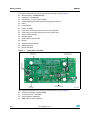
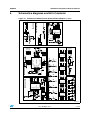
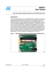
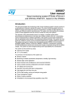
Schematics diagrams and bill of material
Schematics diagrams and bill of material
Figure 19. Schematic of demonstration board STEVAL-ICB003V1 (1 of 2)
$/0550#&.06/5&%
!-V
21/28
22/28
Doc ID 16031 Rev 1
*1'
9
:$*2&211
-
5
N
&
X)
',*B%8==
6(*
9
&
Q)
84&/403@*/165
9
9
4
675
%8==(5
527$725
9
4
4
5(6(7
+&)075
966
9''
3KL
8
5
N
5
N
:$7(56(16256(&7,21
%8==(56(&7,21
6(*
5
N
',*B%8==
',*B%8==
6(*
%=
-
9
'
%$7-
5
.(<
5
5
'
5
N
5
N
%$7-
'
%$7-
&
Q)
&
Q)
4
675
5
N
5
N
9
5
N
.(<
6(*
6(*
$
$
%
9&&
&/5
'
&.
35
4
4
9
%
%
$
5
N
5
5
&
Q)
5
5
'
/('
'
/('
7.B/('
7.B/('
5
5
5
5
5
5
'
/('
'
/('
'
/('
'
/('
'
/('
'
/('
7.B/('
7.B/('
7.B/('
7.B/('
7.B/('
7.B/('
'
%$7-
527$7256(&7,21
0+&5075
&/5
'
&5
35
4
4
966
8
9
6(*
.(<
Schematics diagrams and bill of material
UM0756
Figure 20. Schematic of demonstration board STEVAL-ICB003V1 (2 of 2)
!-V
UM0756
Table 7.
Cat.
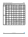
Schematics diagrams and bill of material
Bill or material
S.
Ref.
Component
Package
no. designator
descr.
Manuf.
Orderable
part no.
Supplier
Supplier
order code
Qty
U1
STM8
microcont.
LQFP
ST
STM8S207K
6T6C
ST
STM8S207K
6T6C
1
2
U2
STMPE121
8S/touch
key
controller
QFN40
ST
STMPE1208
SQTR
ST
STMPE1208
SQTR
1
3
U3
HCF4020M
013TR/
counter
SO-16
ST
HCF4020M0
13TR
ST
HCF4020M0
13TR
1
4
U8
STLED316S
/LED driver
SO-20
ST
STLED316S
MTR
ST
STLED316S
MTR
1
5
U9
LD1117V50
/regulator
TO-220
ST
LD1117V50
ST
LD1117V50
1
6
U10
M74HC74R
M13TR, flipflop
SO-16
ST
M74HC74RM
13TR
ST
M74HC74R
M13TR
1
7
D1, D13
STPSIL30A/
Schottky
diode
SMA
ST
STPS1L30A
ST
STPS1L30A
2
8
D3,D14,
D15, D16
BAT54
signal diode
SOD323
ST
BAT54JFILM
ST
BAT54JFILM
4
9
Q1,Q2,Q3
2STR1215
small signal
BJT
SOT23
ST
2STR1215
ST
2STR1215
3
10
J1, 6
3 pin WAGO
5 mm
pitch
Panasonic
ECG
PA001-3 or
equivalent
Farnell
1357319
2
11
J2
SMD with
mm pitch
ERNI
284697
ERNI
284697
1
Connecto
rs and
jumpers 12
4 pin SWIM
connector
J3
6 x 2 pin DIL
Berg
2.5 mm
pitch
Any
13
J4
Power jack
6 mm
Cliff
Electronic
Comp.
1
ST
devices
Doc ID 16031 Rev 1
1
DC10B or
equivalent
Farnell
224960
1
23/28
Schematics diagrams and bill of material
Table 7.
Cat.
Bill or material (continued)
S.
Ref.
Component
Package
no. designator
descr.
Manuf.
Orderable
part no.
Supplier
Supplier
order code
Qty
D2,D4,D5,D
14 6,D7,D8,D9
,D10, D11
LED red
LED-3
mm
Multicop
MCL034PD
or equivalent
Farnell
1581112
9
15
D12
Bicolor LED
5 mm
Dialight
Corp.
521-9628F or
equivalent
Farnell
1461589
1
16
D17,D18,
D19,D20,
D47
Red SMD
LED for
touch
recognition
SMD0805
Panasonic
SSG
LNJ206R5R
UX or
equivalent
Digi-Key
P11496TRND
5
17
D22,D23,
D24
Green SMD
LED for
Panasonic
SMD0805
touch
SSG
recognition
LN1371SGT
R or
equivalent
Digi-Key
P516TR-ND
3
18
U4,U5,U6,U
7
HDSP5501
common
anode
0.55 inch,
2.5 mm
pitch
Avago
Tech.
HDSP-5501
or equivalent
Farnell
1003293
4
19
C9,C10,C1
1,C21,C22,
C23,C24,
C25,C26
2 pF
SMD0805
Panasonic
ECG
ECJ2VC1H020C
or equivalent
Digi-Key
PCC020CNT
R-ND
9
C2,C5,C7,C
12,C14,
20
C15,C16,
C17,C18
100 nF
SMD0805
Panasonic
ECG
ECJ2VB1E104K
or equivalent
Digi-Key
PCC1828CTND
9
21
C3
470 nF
SMD0805
Panasonic
ECG
ECJ2VF1C474Z
or equivalent
Digi-Key
PCC1847TR
-ND
1
22
C1,C4,C6,C
8,C13,C20,
10 µF/10 V
tantalum
Type 1
Vishay/
Sprague
293D106X96
R3A2TE3 or
equivalent
Mouser
74293D106X96
R3A2TE3
6
23
C19
100 µF/25 V
Through
hole
Multicop
MCGPR25V1
07M6.3X11
or equivalent
Farnell
9451188
1
LEDs
Capac.
24/28
UM0756
Doc ID 16031 Rev 1
UM0756
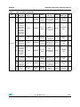
Table 7.
Cat.
Schematics diagrams and bill of material
Bill or material (continued)
S.
Ref.
Component
Package
no. designator
descr.
Manuf.
Orderable
part no.
Supplier
Supplier
order code
Qty
24
R14
0
SMD0805
Panasonic
ECG
ERJ6GEY0R00V
or equivalent
Digi-Key
P0.0ATR-ND
or equivalent
1
25
R17,R18,
R19,R20,
R21,R22
R23,R24,
R43,R44,
R45,R46,
R47,R48,
R49,R50,
R11,R15
220 Ω
SMD0805
Panasonic
ECG
ERJ6GEYJ221V
or equivalent
Digi-Key
P220ATRND
18
26
R25
360 Ω
SMD0805
Panasonic
ECG
ERJ6GEYJ361V
or equivalent
Digi-Key
P360ATRND
1
27
R34,R37,
R38,R39
470 Ω
SMD0805
Panasonic
ECG
ERJ6GEYJ471V
or equivalent
Digi-Key
P470ATRND
4
R5,R9,R10,
R13,R28,
R29,R30,
28 R31,R33,
R34,R35,
R37,R38,
R39
1kΩ
SMD0805
Panasonic
ECG
ERJ6GEYJ102V
or equivalent
Digi-Key
P1.0KATRND
14
R1,R2,R3,R
29 6,R7,R8,R2
6,R40, R41
4.7 kΩ
SMD0805
Panasonic
ECG
ERJ6GEYJ472V
or equivalent
Digi-Key
P4.7KATRND
9
Resistors
30
R4,R12,
R16,R32,
R36,R42
10 kΩ
SMD0805
Panasonic
ECG
ERJ6GEYJ103V
or equivalent
Digi-Key
P10KACTND
6
31
R27
POT - 0 to 1
kΩ
Through
hole
VISHAY
Spectrol
63M-T607102 or
equivalent
Farnell
9608206
1
Doc ID 16031 Rev 1
25/28
Schematics diagrams and bill of material
Table 7.
Cat.
Misc
Compon
ents
Note:
26/28
UM0756
Bill or material (continued)
S.
Ref.
Component
Package
no. designator
descr.
Manuf.
Orderable
part no.
Supplier
Supplier
order code
Qty
32
SW1
Tact switch
Through
hole
Tyco
Electronics
FSM6JH
Farnell
1555983
1
33
J5
Rotary
encoder
Through
hole
ALPS
EC12E24244
07
Farnell
1520813
1
34
RL1
SPDT relay
Through
hole
Multicomp
HRM-S
DC5V
Farnell
9480021
1
35
BZ1
Buzzer DC
Through
hole
Kingstate
KPEG242
Farnell
1502726
1
36
Bump on
Bumpers
small
hemisphere
WHT
Paste
3M
Electronic
Specialty
SJ-5003
Mouser
517-SJ5003WH
4
37
Heat sink
Heat sink for
TO-220
packaged IC
-
Futurlec
TO220LGBA
or equivalent
Futurlec
TO220LGBA
or equivalent
1
C25 not to be mounted
Doc ID 16031 Rev 1
UM0756
7
Revision history
Revision history
Table 8.
Document revision history
Date
Revision
09-Oct-2009
1
Changes
Initial release.
Doc ID 16031 Rev 1
27/28
UM0756
Please Read Carefully:
Information in this document is provided solely in connection with ST products. STMicroelectronics NV and its subsidiaries (“ST”) reserve the
right to make changes, corrections, modifications or improvements, to this document, and the products and services described herein at any
time, without notice.
All ST products are sold pursuant to ST’s terms and conditions of sale.
Purchasers are solely responsible for the choice, selection and use of the ST products and services described herein, and ST assumes no
liability whatsoever relating to the choice, selection or use of the ST products and services described herein.
No license, express or implied, by estoppel or otherwise, to any intellectual property rights is granted under this document. If any part of this
document refers to any third party products or services it shall not be deemed a license grant by ST for the use of such third party products
or services, or any intellectual property contained therein or considered as a warranty covering the use in any manner whatsoever of such
third party products or services or any intellectual property contained therein.
UNLESS OTHERWISE SET FORTH IN ST’S TERMS AND CONDITIONS OF SALE ST DISCLAIMS ANY EXPRESS OR IMPLIED
WARRANTY WITH RESPECT TO THE USE AND/OR SALE OF ST PRODUCTS INCLUDING WITHOUT LIMITATION IMPLIED
WARRANTIES OF MERCHANTABILITY, FITNESS FOR A PARTICULAR PURPOSE (AND THEIR EQUIVALENTS UNDER THE LAWS
OF ANY JURISDICTION), OR INFRINGEMENT OF ANY PATENT, COPYRIGHT OR OTHER INTELLECTUAL PROPERTY RIGHT.
UNLESS EXPRESSLY APPROVED IN WRITING BY AN AUTHORIZED ST REPRESENTATIVE, ST PRODUCTS ARE NOT
RECOMMENDED, AUTHORIZED OR WARRANTED FOR USE IN MILITARY, AIR CRAFT, SPACE, LIFE SAVING, OR LIFE SUSTAINING
APPLICATIONS, NOR IN PRODUCTS OR SYSTEMS WHERE FAILURE OR MALFUNCTION MAY RESULT IN PERSONAL INJURY,
DEATH, OR SEVERE PROPERTY OR ENVIRONMENTAL DAMAGE. ST PRODUCTS WHICH ARE NOT SPECIFIED AS "AUTOMOTIVE
GRADE" MAY ONLY BE USED IN AUTOMOTIVE APPLICATIONS AT USER’S OWN RISK.
Resale of ST products with provisions different from the statements and/or technical features set forth in this document shall immediately void
any warranty granted by ST for the ST product or service described herein and shall not create or extend in any manner whatsoever, any
liability of ST.
ST and the ST logo are trademarks or registered trademarks of ST in various countries.
Information in this document supersedes and replaces all information previously supplied.
The ST logo is a registered trademark of STMicroelectronics. All other names are the property of their respective owners.
© 2009 STMicroelectronics - All rights reserved
STMicroelectronics group of companies
Australia - Belgium - Brazil - Canada - China - Czech Republic - Finland - France - Germany - Hong Kong - India - Israel - Italy - Japan Malaysia - Malta - Morocco - Philippines - Singapore - Spain - Sweden - Switzerland - United Kingdom - United States of America
www.st.com
28/28
Doc ID 16031 Rev 1