1
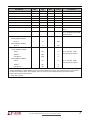
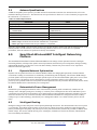
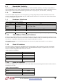
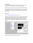
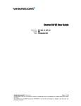
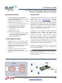
LTP5903-WHR SmartMesh WirelessHART Network Manager Wireless Embedded Network Manager NETWORK FEATURES • • • • DESCRIPTION Complete Radio Transceiver, Embedded Processor, and Networking Software for Forming a Self-Healing Mesh Network Compliant to WirelessHART (IEC62591) Standard SmartMesh Networks Incorporate: • Time Synchronized Network-Wide Scheduling • Per Transmission Frequency Hopping • Redundant Spatially Diverse Topologies • Network-Wide Reliability and Power Optimization • NIST Certified Security SmartMesh Networks Deliver: • >99.999% Network Reliability Achieved in the Most Challenging Dynamic RF Environments Often Found in Industrial Applications • Sub 50µA Routing Nodes LTP5903-WHR FEATURES • • • • Manages Networks of Up to 250 Nodes (LTP5903WHRB) or Up to 500 Nodes (LTP5903-WHRC) Dynamic network optimization maintains network health and enables greater than 99.999% network reliability even in the most challenging environments Comprehensive APIs deliver rich and flexible functionality without complex coding RF Modular Certifications Include USA, Canada, EU, Japan SmartMesh® WirelessHART wireless sensor networks are self managing, low power networks built from wireless nodes SmartMesh called motes. The LTP™5903-WHR WirelessHART embedded manager is the printed circuit board assembly product running Dust’s embedded Smart-Mesh WirelessHART networking software. The LTP5903-WHR is designed for use in line-powered gateways and controllers, such as WirelessHART Gateways, and enables customers to integrate a standards-based wireless sensor network that provides scalable bidirectional communications. Compliant to the WirelessHART (IEC62591) standard, the LTP5903-WHR runs SmartMesh WirelessHART network management software to monitor and manage network performance and provide a data ingress/egress point via Ethernet and UART interfaces. The SmartMesh WirelessHART software provided with the LTP5903-WHR is fully tested and validated, and is readily configured via a software application programming interface. With Dust’s timesynchronized SmartMesh WirelessHART networks, all motes in the network may route, source or terminate data, while providing many years of battery powered operation. SmartMesh WirelessHART motes deliver a highly flexible network with proven reliability and low power performance in an easy-to-integrate platform. , LT, LTC, LTM, Linear Technology, Dust, Dust Networks, Eterna, SmartMesh and the Linear logo are registered trademarks and LTP and the Dust Networks logo are trademarks of Linear Technology Corporation. All other trademarks are the property of their respective owners. Protected by U.S. Patents, including 7375594, 7420980, 7529217, 7791419, 7881239, 7898322, 8222965. For more information www.linear.com/LTP5903-WHR 1 Table of Contents 1.0 Absolute Maximum Ratings ................................................................................4 2.0 Normal Operating Conditions .............................................................................4 3.0 Electrical Specifications .....................................................................................4 3.1 LVTTL I/O DC Specifications ................................................................................ 5 3.2 LED Specifications.............................................................................................. 6 3.3 3.3 V Output Supply........................................................................................... 6 3.4 Device Load ...................................................................................................... 6 3.5 AC Timing Specifications ..................................................................................... 6 4.0 Real-time Clock ..................................................................................................6 5.0 Radio..................................................................................................................6 5.1 Detailed Radio Specifications ............................................................................... 6 5.2 Antenna Specifications........................................................................................ 8 6.0 SmartMesh WirelessHART Intelligent Networking Platform ...............................8 6.1 Dynamic Network Optimization ............................................................................ 8 6.2 Deterministic Power Management......................................................................... 8 6.3 Intelligent Routing ............................................................................................. 8 6.4 Bandwidth Flexibility .......................................................................................... 9 7.0 Interfaces ..........................................................................................................9 7.1 Hardware Interfaces........................................................................................... 9 7.1.1 10/100Base-T Ethernet Interface ................................................................... 9 7.1.2 Serial 1 Interface......................................................................................... 9 7.1.3 Serial 2 Interface......................................................................................... 9 7.1.4 SD Card Interface .......................................................................................10 7.1.5 LED Status Indicators..................................................................................10 7.1.6 Restore Signal............................................................................................10 7.2 Software Interfaces...........................................................................................12 7.2.1 XML API ....................................................................................................12 7.2.2 Admin Toolset ............................................................................................12 7.2.3 Command Line Interface..............................................................................12 8.0 Board-to-board Connectors ..............................................................................12 8.1 Connector Pin Numbering...................................................................................12 8.2 Pinout .............................................................................................................13 8.3 Recommended Mating Connectors .......................................................................15 9.0 Mechanical Specifications.................................................................................15 9.1 10.0 LTP5903-WHR Mechanical Drawings ....................................................................15 Regulatory and Standards Compliance .............................................................16 10.1 FCC Compliance ...............................................................................................16 10.1.1 FCC Testing ...............................................................................................16 10.1.2 FCC-approved Antenna................................................................................17 2 For more information www.linear.com/LTP5903-WHR 10.1.3 OEM Labeling Requirements .........................................................................17 10.2 IC Compliance ..................................................................................................17 10.2.1 IC Testing..................................................................................................17 10.2.2 IC-approved Antennae ................................................................................17 10.2.3 OEM Labeling Requirements .........................................................................17 10.3 CE Compliance .................................................................................................18 10.3.1 Declaration of Conformity ............................................................................18 10.3.2 European Compliance..................................................................................18 10.3.3 OEM Labeling Requirements .........................................................................18 10.3.4 Restrictions................................................................................................18 10.4 Compliance to Japan Radio Law ..........................................................................18 10.4.1 OEM Labeling Requirements .........................................................................18 10.4.2 Antenna Selection.......................................................................................19 10.5 Compliance to Restriction of Hazardous Substances (RoHS) ....................................19 10.6 Industrial Environment Operation........................................................................19 11.0 Order Information............................................................................................19 12.0 Related Documentation ....................................................................................19 For more information www.linear.com/LTP5903-WHR 3 1.0 Absolute Maximum Ratings The absolute maximum ratings shown below should not be violated under any circumstances. Permanent damage to the device may be caused by exceeding one or more of these parameters. Table 1 Absolute Maximum Ratings Parameter Min Supply voltage (+5V_IN to GND) Typ –0.3 Input RF level Storage temperature range –40 VSWR of antenna Max Units 6 V 10 dBm +85 °C Comments Input power at antenna connector 3:1 ESD protection Antenna connector ±8000 V HBM All other connectors ±2 kV HBM ±200 V CDM All voltages are referenced to GND Caution! ESD sensitive device. Precaution should be used when handling the device in order to prevent permanent damage. 2.0 Table 2 Normal Operating Conditions Normal Operating Conditions Parameter Min Typ Max Units 4.0 5.0 5.5 VDC Including noise and load regulation Voltage supply noise 100 mVp-p 50 Hz–50 MHz Peak current 350 mA +3V3 out = 0 mA 150 mA +5V_IN at 5.0 V, 25 °C, +3V3 out = 0 mA 225 mA +5V_IN at 5.0 V, 25 °C, +3V3 out = 100 mA Operational supply voltage range (between +5V_IN and GND) Comments Average current Operating temperature range –40 Maximum allowed temperature ramp during operation Operating relative humidity 10 +85 °C 8 °C/min –40 °C to +85 °C 90 % RH Non-condensing The specifications listed are for the power supply connected to +5V_IN and GND, and apply over the operating temperature range unless otherwise specified. 3.0 Electrical Specifications I/O specifications are given below for each I/O level type given in the board-to-board connector tables in sections 7.1 and 8.2. Unless otherwise noted, +5V_IN is 5.0 V and temperature is –40 °C to +85 °C. 4 For more information www.linear.com/LTP5903-WHR 3.1 Table 3 LVTTL I/O DC Specifications LVTTL Type 1 Specifications Max Units VIH (logical high input) Parameter Min 2.0 Typ 3.6 V VIL (logical low input) -0.3 0.8 V 60 µA 0.4 V IIN (input leakage) VOH (logical high output) 2.6 V VOL (logical low output) IOH (VO = VOH) (source) 8 mA IOL (VO = VOL) (sink) 8 mA Table 4 LVTTL Type 2 Specifications (Schmitt Trigger) Parameter Min Typ Max Units V + Threshold 1.3 2.5 V V – Threshold 0.6 1.6 V ±5 µA Max Units 0.4 V IIN (input leakage) Table 5 Min VOH Typ 2.6 VIN = +3V3 Comments V VOL IOH -12 mA IOL 12 mA LVTTL Type 4 Specifications Parameter Min Typ Max Units V VOH (logical high output) 2.6 +3V3 VOL (logical low output) GND 0.4 IOH (VO = VOH) (source) 2 mA IOL (VO = VOL) (sink) 2 mA Table 7 Comments LVTTL Type 3 Specifications Parameter Table 6 Comments Comments V LVTTL Type 5 Specifications Parameter Min Typ Max Units V VIH (logical high input) 2.6 +3V3 + 0.3 VIL (logical low input) GND – 0.3 GND + 0.8 V ±5 µA IIN (input leakage) For more information www.linear.com/LTP5903-WHR Comments VIN = +3V3 5 3.2 Table 8 LED Specifications LED Specifications Max Units VOH (logical high output) Parameter +3V3 – 0.3 Min Typ +3V3 V VOL (logical low output) GND GND + 0.4 V IOH (VO = VOH) (source) 3 mA Comments +3V3 = 3.3 V IOL (VO = VOL), I/O = LED (sink) 1.5 mA +3V3 = 3.3 V IOL (VO = VOH), I/O = LED low (sink) 0.5 mA +3V3 = 3.3 V 3.3 3.3 V Output Supply The LTP5903-WHR includes a regulated 3.3 V output signal (labeled +3V3) for supplying power to user circuitry (for example, isolation or signal conditioning). Note that any power drawn on +3V3 circuitry results in an increase in power drawn on +5V_IN. Table 10 +3.3 V Power Supply Output Parameter Min Typ Max Units 100 mA 3.47 V Max Units Total capacitance 290 µF Total inductance 15 µH Max Units +3V3 current source +3V3 supply voltage 3.4 3.13 Comments Device Load Table 11 Device Load Parameter 3.5 Min Typ Comments AC Timing Specifications Table 12 AC Timing Specifications Parameter nRESET_IN pulse width 4.0 Min Typ 125 Comments µs Real-time Clock The LTP5903-WHR has a battery-backed real-time clock (RTC) with a typical lifetime of 5-7 years (lifetime up to 15 years if the manager is normally powered), assuming the manager is operating at 60 °C average ambient temperature and at 10% duty cycle. Upon bootup, the RTC initializes the software system clock that handles timekeeping while the system is operating. The software system clock is the reference for UTC time values readable through the software APIs, command line interface (CLI) and Admin Toolset Web interface, as well as the UTC time values visible in manager log files. The system clock may be set manually using the Admin Toolset Web interface, or through the Linux command shell. The accuracy of the software system clock is typically 1 min/month at 25°C, though may vary as much as 10 min/month at temperature extremes. To support applications less tolerant of such drift, the LTP5903-WHR software includes an NTP client to periodically synchronize software system time to an outside source. The NTP client is configurable using the Admin Toolset Web interface, or through the Linux command shell. 5.0 Radio 5.1 Detailed Radio Specifications Table 13 Radio Specifications Parameter Operating frequency 6 Min 2.4000 Typ Max Units 2.4835 GHz For more information www.linear.com/LTP5903-WHR Comments Parameter Min Typ Max Units Number of channels 15 Channel separation 5 MHz 2.7 MHz Occupied channel bandwidth Frequency accuracy -40 +40 Comments At –20 dBc ppm Modulation IEEE 802.15.4 DSSS Raw data rate 250 Receiver operating input level Receiver sensitivity Kbps 0 dBm –92.5 dBm At 50% PER, VDD = 3 V, 25 °C –90 dBm At 1% PER, VDD = 3 V, 25 °C, (inferred by 50% PER measurement) +8 dBm –2 dBm 100 m Output power, conducted Power amplifier enabled: At 25 °C Power amplifier disabled: At 25 °C Range* Power amplifier enabled: Indoor† Outdoor † 300 m 1200 m Indoor† 25 m Outdoor† 200 m Free Space 350 m Free Space 25 °C, 50% RH, +2 dBi omni-directional antenna Power amplifier disabled: 25 °C, 50% RH, +2 dBi omni-directional antenna *Actual RF range performance is subject to a number of installation-specific variables including, but not restricted to ambient temperature, relative humidity, presence of active interference sources, line-of-sight obstacles, near-presence of objects (for example, trees, walls, signage, and so on) that may induce multipath fading. As a result, actual performance varies for each instance. † 1 meter above ground. For more information www.linear.com/LTP5903-WHR 7 5.2 Antenna Specifications A MMCX-compatible jack receptacle is provided on board for the antenna connection. For antenna location, refer to the mechanical drawing in section 9.1. The antenna must meet specifications in Table 14. For a list of antennae pre-approved for RF certification, see section 10.1.2. Table 14 Antenna Specifications Parameter Value Frequency range Impedance 2.4–2.4835 GHz 50 Ω Gain LTP5903-WHR Pattern Maximum VSWR Connector +2 dBi maximum Omni-directional 3:1 MMCX* * The LTP5903-WHR can accommodate the following RF mating connectors: • MMCX straight connector such as Johnson 135-3402-001, or equivalent • MMCX right angle connector such as Tyco 1408149-1, or equivalent When the LTP5903-WHR is placed inside an enclosure, the antenna should be mounted such that the radiating portion of the antenna protrudes from the enclosure, and connected using a MMCX connector on a coaxial cable. For optimum performance, allow the antenna to be positioned vertically when installed. 6.0 SmartMesh WirelessHART Intelligent Networking Platform The SmartMesh WirelessHART LTP5903-WHR embedded network manager is built upon Dust Networks’ Intelligent Networking Platform, which provides dynamic network optimization, deterministic power management, intelligent routing, and bandwidth flexibility to achieve the carrier class data reliability, and ultra-low power and ease of use required for industrial automation applications. 6.1 Dynamic Network Optimization Dynamic network optimization allows the LTP5903-WHR to address the changing RF requirements in harsh industrial environments resulting in a network that is continuously self-monitoring and self-adjusting. The LTP5903-WHR manager performs dynamic network optimization based upon periodic reports on network health and link quality that it receives from the network motes. The manager uses this information to provide performance statistics to the application layer and proactively solve problems in the network. Dynamic network optimization not only maintains network health, but also allows the LTP5903-WHR to deliver deterministic power management. 6.2 Deterministic Power Management Deterministic power management balances traffic in the network by diverting traffic around heavily loaded motes (for example, motes with high reporting rates). In doing so, it reduces power consumption for these motes and balances power consumption across the network. Deterministic power management provides predictable maintenance schedules to prevent down time and lower the cost of network ownership. When combined with field devices using Dust Network’s industryleading low power radio technology, deterministic power management enables over a decade of battery life for network motes. 6.3 Intelligent Routing Intelligent routing provides each packet with an optimal path through the network. The shortest distance between two points is a straight line, but in RF the quickest path is not always the one with the fewest hops. Intelligent routing finds optimal paths by considering the link quality (one path may lose more packets than another) and the retry schedule, in addition to the number of hops. The result is reduced network power consumption, elimination of in-network collisions, and unmatched network scalability and reliability. 8 For more information www.linear.com/LTP5903-WHR 6.4 Bandwidth Flexibility Efficient use of network resources enables Dust Networks to deliver bandwidth flexibility—the ability to assign different levels of bandwidth to satisfy unique throughput and latency requirements. Bandwidth flexibly addresses the range of latency and throughput needs of industrial automation applications such as request/response, fast file transfer, and alerting. 7.0 Interfaces The LTP5903-WHR is designed for ease of integration by providing multiple data ports and well-defined software APIs. Section 7.1 describes the LTP5903-WHR data ports, LEDs, and switches Section 7.1.6 describes the software functions that are available through the data ports. 7.1 Hardware Interfaces Table 15 Hardware Interface Summary Port Description Pins Ethernet 10/100Base-T Ethernet RX_P, TX_P, RX_N, TX_N, RX_CT, TX_CT, nACT_LED, nLINK_LED Serial 1 UART 5-pin S1_TX, S1_RX, GND Serial 2 UART 9-pin S2_TX, S2_RX, S2_RTS, S2_CTS, GND LED Status Indicator Status indicators ¯¯¯ nLED_SUB, nLED_RADIO, nLED_JOIN, RST SD External memory card SD_CS0, SD_CLK, SD_MOSI, SD_MISO, SD_CD, SD_WP 7.1.1 10/100Base-T Ethernet Interface Ideal for remote or high-bandwidth access, the Ethernet interface provides full configuration management and data access to the LTP5903-WHR. The port connects to an IEEE 802.3 standard 10/100Base-T PHY, accessible through the board-to-board J10 connector. An appropriate Ethernet design requires magnetics and an RJ-45 connector. RX_P and RX_N are the receive-side differential pair (see section 8.2 for pinout). The Rx and Tx levels conform to 10/100Base-T Ethernet. 7.1.2 Serial 1 Interface The Serial 1 interface is designed for embedded integration with controllers. This serial interface provides programmatic access for configuration, management, and data access to the LTP5903-WHR. The port is a 5-pin LVTTL (3.3 V) serial interface accessible through the board-to-board J10 connector. Table 16 Serial 1 Parameters Parameter Value Bit rate 115200 Parity N Data bits 8 Stop bit 1 Flow control 7.1.3 None Serial 2 Interface The LTP5903-WHR provides a UART interface with TX, RX, RTS, and CTS lines through the board-to-board J6 connector, operating up to 115 kbps. Table 17 Serial 2 Parameters Parameter Bit rate Value 115200 Parity N Data bits 8 For more information www.linear.com/LTP5903-WHR 9 Parameter Value Stop bit 1 Flow control 7.1.4 None SD Card Interface The SD Card interface, in conjunction with an PHY interface implemented per the LTP5903IPC Integration Guide has been tested against a range of commercially available SD cards and operates per limitations described in the “Datalog Utility” section of the SmartMesh WirelessHART User Guide. The SD Card interface enables a portable non-volatile storage solution, targeting data logging applications. 7.1.5 LED Status Indicators The LTP5903-WHR has LED status indicators on the top surface of the module, whose signals also pass through the boardto-board J10 connector. Table 18 LED Status Indicators LED Name Signal Name Power ¯¯¯ RST 7.1.6 nRESET_IN Description Color Indicates 3.3V DC-DC converter is okay, lights when 5 V supply is connected Green Indicates the manager is in the reset state Red Restore Signal The LTP5903-WHR supports the ability to restore its configuration settings to the Dust factory defaults. This feature is most useful in non-embedded applications where the LTP5903-WHR configuration may be different per installation (for example, a manager’s IP setting is forgotten and therefore unreachable). Note that while the restore feature may be used to recover a previously “unreachable” manager, all customizations to the manager will be lost, including configuration, logs, OTAP directory files, and persistent mote information. The following factory default settings are restored: IP address PPP settings Serial port settings User name and password Wireless network and mote configuration settings Wireless network ID and common join key Access control list (cleared) Log files (cleared) Mote list (cleared) 10 For more information www.linear.com/LTP5903-WHR The Restore Switch signal input to the LTP5903-WHR includes a debounce circuit to support direct connection to a mechanical push button, as illustrated in Figure 1. Figure 1 Restore Switch Debounce Input Stage The Restore Switch signal controls the restore function. The Restore Switch signal is only active for the first three seconds after nRESET_IN is released. Usage of the Restore Switch signal is optional. If unused, the Restore Switch signal may be left unconnected, since it is internally pulled inactive high. tRST to RESTORE nRESET_IN Restore Switch Figure 2 Restore Switch Signal Timing Diagram Table 19 Restore Signal Timing Values Parameter tRST to RESTORE Min 1 Typ Max Units 20 s For more information www.linear.com/LTP5903-WHR Comments 11 7.2 Software Interfaces The LTP5903-WHR provides well-defined software interfaces for easy integration. Table 20 describes which interfaces are available via the various hardware ports. This section describes the software interfaces available via the hardware ports described in section 7.2.1. Table 20 LTP5903-WHR Software Interfaces Hardware Port Software Interface Ethernet XML API, Admin Toolset Serial 1 <reserved> Serial 2 Command line interface 7.2.1 Comments XML API The XML API is an open Extensible Markup Language (XML) interface that lets a client application send Remote Procedure Call (RPC) requests to the LTP5903-WHR and receive responses and other data from the LTP5903-WHR via XML-RPC. The API consists of a Control Channel and a Notification Channel. The Control Channel is used to establish connection and exchange commands and information about the SmartMesh Network. The Notification Channel is used to stream data and network events to the client program 7.2.2 Admin Toolset The LTP5903-WHR provides a Web-based administrative tool called Admin Toolset. Through this interface, users may configure IP settings, view logs, manually configure the system time, or enable the Network Time Protocol (NTP) client. Users may also update LTP5903-WHR software as well as perform remote software updates on motes in the wireless network. 7.2.3 Command Line Interface The command line interface is for troubleshooting with the assistance of Dust Networks support. 8.0 Board-to-board Connectors The LTP5903-WHR has two 40-pin FCI/Berg 61083-042400LF board-to-board connectors. For connector and pin locations, see Figure 3 and Figure 4. 8.1 Figure 3 12 Connector Pin Numbering Connector Pin Numbering (Bottom View) For more information www.linear.com/LTP5903-WHR 8.2 Pinout Table 22 J10 Board-to-board Connector Pin Number Pin Name I/O Direction 1 GND 2 GND 3 RX_P In 10/100Base-T Ethernet 4 TX_P Out 10/100Base-T Ethernet 5 RX_N In 10/100Base-T Ethernet 6 TX_N Out 10/100Base-T Ethernet 7 RX_CT In 10/100Base-T Ethernet 8 TX_CT Out 10/100Base-T Ethernet 9 nACT_LED Out LVTTL Type 3 LED Status indicators 10 nLINK_LED Out LVTTL Type 3 LED Status indicators 11 +3V3 Out 3.3 V ± 5% 3.3 V Out 12 +3V3 Out 3.3 V ± 5% 3.3 V Out 13 Reserved Do not connect 14 Reserved Do not connect 15 Reserved Do not connect 16 Reserved Do not connect Out I/O Level LVTTL Type 1 Interface Name 17 S1_TX 18 Reserved Serial 1 19 S1_RX In LVTTL Type 1 Serial 1 20 Restore Switch In* LVTTL Type 2 Switch In 21 GND 22 nLED_SUB Out LVTTL Type 1 LED status indicators 23 SD_CLK Out LVTTL Type 1 SD clock 24 nLED_JOIN Out LVTTL Type 1 LED status indicators 25 +3V3 Out 3.3 V ± 5% 26 Reserved Do not connect 3.3 V Out Do not connect 27 SD_CD 28 Reserved Do not connect 29 Reserved Do not connect 30 SD_CS0 31 SD_WP 32 Reserved 33 GND 34 Reserved 35 SD_MISO 36 Reserved 37 SD_MOSI 38 Reserved 39 GND 40 GND LVTTL Type 1 Out LVTTL Type 1 LVTTL Type 1 SD Card detect SD Card chip select SD Card write protect Do not connect Do not connect LVTTL Type 1 SD Card data in Do not connect LVTTL Type 1 SD Card data out Do not connect * Input includes a debounce input stage as illustrated in Figure 1. For more information www.linear.com/LTP5903-WHR 13 Table 23 J6 Board-to-board Connector Pin Number Pin Name 1 GND 2 GND 3 Reserved 4 S2_TX 5 Reserved 6 S2_RX 7 Reserved I/O Direction I/O Level Interface Name Do not connect Out LVTTL Type 1 Serial 2 Do not connect In LVTTL Type 1 Serial 2 Do not connect 8 S2_RTS 9 Reserved Out LVTTL Type 1 Serial 2 10 S2_CTS 11 Reserved Do not connect 12 Reserved Do not connect 13 Reserved Do not connect 14 Reserved Do not connect Do not connect In LVTTL Type 1 Serial 2 15 GND 16 Reserved Do not connect 17 Reserved Do not connect 18 Reserved Do not connect 19 Reserved Do not connect 20 +3V3 Out 3.3 V ± 5% 3.3 V Out 21 +3V3 Out 3.3 V ± 5% 3.3 V Out 22 nRESET_OUT Out LVTTL Type 4 23 Reserved 24 GND Reset low out Do not connect 25 Reserved 26 RESET_OUT 27 Reserved 28 nRESET_IN 29 Reserved Do not connect 30 Reserved Do not connect 31 Reserved Do not connect 32 +5V_IN 33 Reserved 34 +5V_IN 35 GND Do not connect Out LVTTL Type 4 Do not connect In** In LVTTL Type 5 5.0 V ± 5% Reset low in Power In Do not connect In 5.0 V ± 5% Power In Power In 36 +5V_IN In 5.0 V ± 5% 37 nLED_RADIO Out LED 38 Reserved 39 GND 40 GND LED status indicators Do not connect * Input includes a 10kΩ resistor pulled to +3V3. 14 Reset high out For more information www.linear.com/LTP5903-WHR 8.3 Recommended Mating Connectors The user connections are made through J6 and J10 on the LTP5903-WHR, which are FCI/Berg 61083-042400LF board-toboard connectors. The mating connector should be an FCI/Berg 61082-04x400LF, where ‘x’ depends on the desired stack height (see Table 24). Table 24 Recommended Mating Connectors Connector Mated Height (mm) FCI/Berg 61082-041400LF 6 FCI/Berg 61082-042400LF 10 FCI/Berg 61082-043400LF 14 9.0 Mechanical Specifications 9.1 LTP5903-WHR Mechanical Drawings In laying out a design, locate the mating connectors by using the alignment pins and correlating pin numbers for orientation (see Figure 3). For more information www.linear.com/LTP5903-WHR 15 Figure 4 Top and Side Views Figure 5 Bottom View 10.0 Regulatory and Standards Compliance 10.1 FCC Compliance 10.1.1 FCC Testing The LTP5903-WHR Embedded Manager complies with Part 15.247 modular (Intentional Radiator) of the FCC rules and regulations. In order to fulfill FCC certification requirements, products incorporating the LTP5903-WHR Embedded Manager must comply with the following: 1. An external label must be provided on the outside of the final product enclosure specifying the FCC identifier, as described in section 10.1.3 below. 2. The antenna must be electrically identical to the FCC-approved antenna specifications for the LTP5903-WHR as described in 10.1.2, with the exception that the gain may be lower than specified in Table 25. 16 For more information www.linear.com/LTP5903-WHR 3. The device integrating the LTP5903-WHR may not cause harmful interference, and must accept any interference received, including interference that may cause undesired operation. 4. An unintentional radiator scan must be performed on the device integrating the LTP5903-WHR Embedded Manager, per FCC rules and regulations, CFR Title 47, Part 15, Subpart B. See FCC rules for specifics on requirements for declaration of conformity. 10.1.2 FCC-approved Antenna The following are FCC-approved antenna specifications for the LTP5903-WHR. Table 25 FCC-approved Antenna Specifications for the LTP5903-WHR Gain Pattern +2 dBi maximum 10.1.3 Omni-directional Polarization Vertical Frequency 2.4–2.4835 GHz Connector MMCX OEM Labeling Requirements The Original Equipment Manufacturer (OEM) must ensure that FCC labeling requirements are met. The outside of the final product enclosure must have a label with the following (or similar) text specifying the FCC identifier. The FCC ID and certification code must be in Latin letters and Arabic numbers and visible without magnification. Contains transmitter module FCC ID: SJC-M2140 or Contains FCC ID: SJC-M2140 10.2 IC Compliance 10.2.1 IC Testing The LTP5903-WHR is certified for modular Industry Canada (IC) RSS-210 approval. The OEM is responsible for its product to comply with IC ICES-003 and FCC Part 15, Sub. B - Unintentional Radiators. The requirements of ICES-003 are equivalent to FCC Part 15 Sub. B and Industry Canada accepts FCC test reports or CISPR 22 test reports for compliance with ICES-003. 10.2.2 IC-approved Antennae The LTP5903-WHR is designed to operate with antennas meeting the specifications shown in Table 26. Antennas not meeting these specifications are strictly prohibited for use with the LTP5903-WHR. The required antenna impedance is 50 Ohms. Operation is subject to the following two conditions: (1) this device may not cause interference, and (2) this device must accept any interference, including interference that may cause undesired operation of the device. Table 26 IC-approved Antenna Specifications for the LTP5903-WHR Gain Pattern +2 dBi maximum Omni-directional Polarization Vertical Frequency 2.4–2.4835 GHz Connector MMCX The following are IC-approved antenna specifications for the LTP5903-WHR. 10.2.3 OEM Labeling Requirements The Original Equipment Manufacturer (OEM) must ensure that IC labeling requirements are met. The outside of the final product enclosure must have a label with the following (or similar) text specifying the IC identifier. The IC ID and certification code must be in Latin letters and Arabic numbers and visible without magnification. Contains IC: 5853A-M2140 For more information www.linear.com/LTP5903-WHR 17 10.3 CE Compliance 10.3.1 Declaration of Conformity We, Dust Networks, of 30695 Huntwood Ave, Hayward, CA 94544 USA, declare under our sole responsibility that our product, SmartMesh WirelessHART LTP5903-WHR, and in combination with our accessories, to which this declaration relates is in conformity with the appropriate standards ETSI EN 300 328, ETSI EN 301 489-17 and EN 60950, following the provisions of Radio Equipment and Telecommunication Terminal Equipment Directive 99/5/EC with requirements covering EMC Directive 2004/108/EC, and Low Voltage Directive 2006/95/EC. 10.3.2 European Compliance If the LTP5903-WHR managers are incorporated into a product, the manufacturer must ensure compliance of the final product to the European harmonized EMC and low-voltage/safety standards. A Declaration of Conformity must be issued for each of these standards and kept on file as described in Annex II of the R&TTE Directive. Furthermore, the manufacturer must maintain a copy of this LTP5903-WHR user documentation and ensure the final product does not exceed the specified power ratings, antenna specifications, and/or installation requirements as specified in the user manual. If any of these specifications are exceeded in the final product, a submission must be made to a notified body for compliance testing to all required standards. 10.3.3 OEM Labeling Requirements The ‘CE’ marking must be affixed to a visible location on the OEM product. The CE mark shall consist of the initials “CE” taking the following form: If the CE marking is reduced or enlarged, the proportions given in the drawing below must be respected. The CE marking must have a height of at least 5 mm except where this is not possible on account of the nature of the apparatus. The CE marking must be affixed visibly, legibly, and indelibly. Furthermore, since the usage of the 2400 – 2483.5 MHz band is not harmonized throughout Europe, the Restriction sign must be placed to the right of the ‘CE’ marking as shown below. See the R&TTE Directive, Article 12 and Annex VII for more information. Figure 6 10.3.4 CE Label Requirements Restrictions Norway prohibits operation near Ny-Alesund in Svalbard. More information can be found at the Norway Posts and Telecommunications site (www.npt.no). 10.4 Compliance to Japan Radio Law The M2510 modular radio incorporated in the LTP5903-WHR is compliant to Japan Radio Law Article 38, Section 24. 10.4.1 OEM Labeling Requirements The Original Equipment Manufacturer (OEM) must ensure that Japan Radio Law labeling requirements are met. The outside of the final product enclosure must have a label including the Mark, , and the symbol indicating radio equipment and the identification code as follows: 18 For more information www.linear.com/LTP5903-WHR Figure 7 The Mark, JRL Label Requirements , must be reproduced with a minimum diameter of 3mm. 10.4.2 Antenna Selection The LTP5903-WHR incorporating the M2510 module may be used with the following antennas: Table 27 Japan Approved Antennas Manufacturer Part # Fractus FR05-S1-N-0-102 Nearson S181XX-2450S 10.5 Peak Gain 1.5 dBi 2 dBi Compliance to Restriction of Hazardous Substances (RoHS) Restriction of Hazardous Substances (RoHS) is a directive that places maximum concentration limits on the use of certain hazardous substances in electrical and electronic equipment. Linear Technology is committed to meeting the requirements of the European Community directive 2002/95/EC. This product has been specifically designed to utilize RoHS compliant materials and to eliminate, or reduce, the use of restricted materials to comply with 2002/95/EC. The Linear Technology RoHS compliant design features include: RoHS compliant solder for solder joints RoHS compliant base metal alloys RoHS compliant precious metal plating RoHS compliant cable assemblies and connector choices 10.6 Industrial Environment Operation The LTP5903-WHR is designed to meet the specifications of a harsh industrial environment that includes: Shock and Vibration—The LTP5903-WHR complies with high vibration pipeline testing, as specified in IEC 60770-1. Temperature Extremes—The LTP5903-WHR is designed for industrial storage and operational temperature range of –40 °C to +85 °C. 11.0 Order Information LEAD FREE FINISH** PART MARKING PACKAGE DESCRIPTION TEMPERATURE RANGE LTP5903IPC-WHRB???#PBF LTP5903 4.050” x 2.190” x 0.775 PCB -40 °C to 85 °C LTP5903IPC-WHRC???#PBF LTP5903 4.050” x 2.190” x 0.775 PCB -40 °C to 85 °C ** See www.linear.com/ltp5903-whr#orderinfo or contact your sales representative to determine the three digit software version field, ???. For more information on lead free part marking, go to: http://www.linear.com/leadfree/ 12.0 Related Documentation LTP5903IPC Integration Guide For more information www.linear.com/LTP5903-WHR 19 Copyright This documentation is protected by United States and international copyright and other intellectual and industrial property laws. It is solely owned by Dust Networks, Inc. and its licensors and is distributed under a restrictive license. This product, or any portion thereof, may not be used, copied, modified, reverse assembled, reverse compiled, reverse engineered, distributed, or redistributed in any form by any means without the prior written authorization of Dust Networks, Inc. RESTRICTED RIGHTS: Use, duplication, or disclosure by the U.S. Government is subject to restrictions of FAR 52.227-14(g) (2)(6/87) and FAR 52.227-19(6/87), or DFAR 252.227-7015 (b)(6/95) and DFAR 227.7202-3(a), and any and all similar and successor legislation and regulation. Disclaimer This documentation is provided “as is” without warranty of any kind, either expressed or implied, including but not limited to, the implied warranties of merchantability or fitness for a particular purpose. This documentation might include technical inaccuracies or other errors. Corrections and improvements might be incorporated in new versions of the documentation. Dust Networks does not assume any liability arising out of the application or use of any products or services and specifically disclaims any and all liability, including without limitation consequential or incidental damages. Dust Networks products are not designed for use in life support appliances, devices, or other systems where malfunction can reasonably be expected to result in significant personal injury to the user, or as a critical component in any life support device or system whose failure to perform can be reasonably expected to cause the failure of the life support device or system, or to affect its safety or effectiveness. Dust Networks customers using or selling these products for use in such applications do so at their own risk and agree to fully indemnify and hold Dust Networks and its officers, employees, subsidiaries, affiliates, and distributors harmless against all claims, costs, damages, and expenses, and reasonable attorney fees arising out of, directly or indirectly, any claim of personal injury or death associated with such unintended or unauthorized use, even if such claim alleges that Dust Networks was negligent regarding the design or manufacture of its products. Dust Networks reserves the right to make corrections, modifications, enhancements, improvements, and other changes to its products or services at any time and to discontinue any product or service without notice. Customers should obtain the latest relevant information before placing orders and should verify that such information is current and complete. All products are sold subject to Dust Network's terms and conditions of sale supplied at the time of order acknowledgment or sale. Dust Networks does not warrant or represent that any license, either express or implied, is granted under any Dust Networks patent right, copyright, mask work right, or other Dust Networks intellectual property right relating to any combination, machine, or process in which Dust Networks products or services are used. Information published by Dust Networks regarding third-party products or services does not constitute a license from Dust Networks to use such products or services or a warranty or endorsement thereof. Use of such information may require a license from a third party under the patents or other intellectual property of the third party, or a license from Dust Networks under the patents or other intellectual property of Dust Networks. Dust Networks, Inc is a wholly owned subsidiary of Linear Technology Corporation. © Dust Networks, Inc. 2013. All Rights Reserved. Document Status Document Number: 020-0051 rev 5 SmartMesh WirelessHART LTP5903-WHR Datasheet Last Revised: November 1, 2013 Product Status Definition Advanced Information Planned or under development This datasheet contains the design specifications for product development. Dust Networks reserves the right to change specifications in any manner without notice. Preliminary Engineering samples and pre-production prototypes This datasheet contains preliminary data; supplementary data will be published at a later time. Dust Networks reserves the right to make changes at any time without notice in order to improve design and supply the best possible product. The product is not fully qualified at this point. No Identification Noted Full production This datasheet contains the final specifications. Dust Networks reserves the right to make changes at any time without notice in order to improve design and supply the best possible product. Obsolete Not in production This datasheet contains specifications for a product that has been discontinued by Dust Networks. The datasheet is printed for reference information only. 20 For more information www.linear.com/LTP5903-WHR